Questions about my DIY Launch Controller

The Rocketry Forum

Help Support The Rocketry Forum:

This site may earn a commission from merchant affiliate links, including eBay, Amazon, and others.
Sorry, I wan't clear.

Look at this pic:
NJ0zHkm.jpg

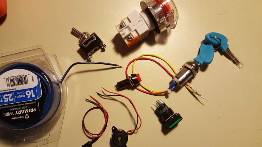
On the left we have the roll of 16 gauge wire that I already bought for this job.

Clockwise, the main power toggle w/ big screw terminals, the Ignition button, the Keyswitch, another button, the piezo, an LED and the Continuity Test button in the middle (with the little tiny terminals). All of these are 12V 10A parts (at least).

Now I certainly plan to use the 16 gauge wire for the battery terminals and main power and ignition and the XLR connectors to the pad.

But that lighter duty wire they used for the leads on the LED and piezo is obviously adequate for those purposes and isn't that right wire for the continuity test and the little electronic connections in the box?

Don't I need a roll of that too?
 
The high current ignition wiring will use your 16 AWG wire; the low current wiring for the leds, piezo and continuity can use the lighter wire. Do you need a roll of that? Well, that depends on how you propose to do the wiring. Wouldn't hurt to buy a roll. You might also find solder terminal strips or screw terminal strips would make your internal wiring easier.
shopping

shopping
 
So I started soldering things together:

You call this FLUX?!

What is this stuff?! it boils away!

Where do I find the good old lead solder and the poisonous acid flux?
Yes, it was poisonous... so?

/I'm old
 
A little late, but for what it's worth:

Design a circuit so that you can add more bells and whistles later, because you'll want to: Pad selected lights at the pad, continuity test at the pad, volt meters, warning horns, etc.

XLR cables can be as low as 24 gauge, so be careful if you use long lengths (or use a relay box at the pad). As others have said, extension cords are about the cheapest heavy gauge wire you can get.

A sealed lead acid 12v battery is a good cost effective choice for power. You can use one of those and ignite copperheads without a relay from 50' with a cheap extension cord as the wire.

Horn relays or other automotive relays are readily available and can switch a lot of current at the pad.

Good but inexpensive toggle switches are getting harder to find (all decent but inexpensive discrete electronics are getting hard to find--remember the days when there were storefronts in every town for places like this: https://www.surpluscenter.com/Electrical/Switches/Toggle-Switches/ ?) But I've seen household light switches used to good effect--and they're cheap if a bit more painful to mount.

Be careful wiring the continuity circuit, if you use one; it is possible to have enough current going through a regular bulb to ignite a low-current igniter. It is also possible, if you use relays pad selection switches and other bells and whistles, to have a circuit that allows current to flow in unintended ways. It is also easy to have relay coils generate emf that damages electronics, so be careful mixing solid state devices with electromechanical ones. (https://progeny.co.uk/back-emf-suppression/)

It goes without saying to make sure you ground test everything first!
 
For plumbing you use acid flux, never for electronics. Electronics require rosin flux.

I was just grousing.

I did the electronics hobby too, when I was a kid. I had this little blue metal box with a huge skull and crossbones, and it had this brown vaseline inside. (maybe it wasn't acid) Boy was that flux, a dab of that on the connection and it practically pulled the solder off the pencil.

But that was before the last 40 years of health, safety and environmental regulations. Lord only knows what was in that acrid smoke that wafted into my face as I was working. Or how much poison I was just throwing in the trash.

This new water soluble "flux" boils away, so quickly I've had to learn a new technique of brushing the solder pencil on the the connection and fast. But I'm getting there
 
Last edited:
A little late, but for what it's worth:

Design a circuit so that you can add more bells and whistles later, because you'll want to: Pad selected lights at the pad, continuity test at the pad, volt meters, warning horns, etc.

I'm well ahead of you on all that (the features and the project phasing)

XLR cables can be as low as 24 gauge, so be careful if you use long lengths (or use a relay box at the pad). As others have said, extension cords are about the cheapest heavy gauge wire you can get.

As well established higher in this thread I know nothing about wire gauge. However I am smart enough to read specs and ratings. XLR cables are designed for 24 volt systems, and rated for 50 volts. A typical mic cable can carry 48 volts of phantom power. I figure my 12 volts / 4 amps are safe.

Pricewise (assuming you want plugs on the ends of the wires and aren't just hardwiring in the cable) XLR cables can be cheaper than extension cords. This 25' mic cable cost $7 and has ends. Cutting the ends off a 120VAC cable and adding some connectors will cost more than $7 (and take time and effort).

Be careful wiring the continuity circuit, if you use one; it is possible to have enough current going through a regular bulb to ignite a low-current igniter. It is also possible, if you use relays pad selection switches and other bells and whistles, to have a circuit that allows current to flow in unintended ways. It is also easy to have relay coils generate emf that damages electronics, so be careful mixing solid state devices with electromechanical ones. (https://progeny.co.uk/back-emf-suppression/)

Which brings me to a specific question:

What amount of power will set off a typical (Estes) igniter? (ie what is the max safe voltage for a continuity test and the min required voltage for ignition?)
 
Last edited:
Houston, we have beeping!

So I decided to start w/ the flasher circuit kit just to brush up on my soldering skills. It was a palm-sized bag of parts. That's all, not even a schematic (other than the printing on circuit board). It cost 99 cents with free shipping.

I haven't done any soldering in 30 years other than fixing a lamp now and then. Boy was that fun! I can honestly say I have never in my life had as much fun for 99 cents.

It's a little messy but totally functional. I don't think a 52 year old man ever giggled quite so much at two flashing lights. But adding the piezo didn't work. The flashing seems dependent on the current draw, and putting so much pull on one side, it never flipped over to the other side, just a solid "beeeeeeeeeeeeeeeeeee..."

But as I'm pinching wires together to test things, at one point one of the piezo leads comes loose, falls on to another exposed connection, AND BEEPS for just a second. It takes me a few moments to figure out I did. I put the piezo between the two sides. that worked. (I laughed like a mad scientist)

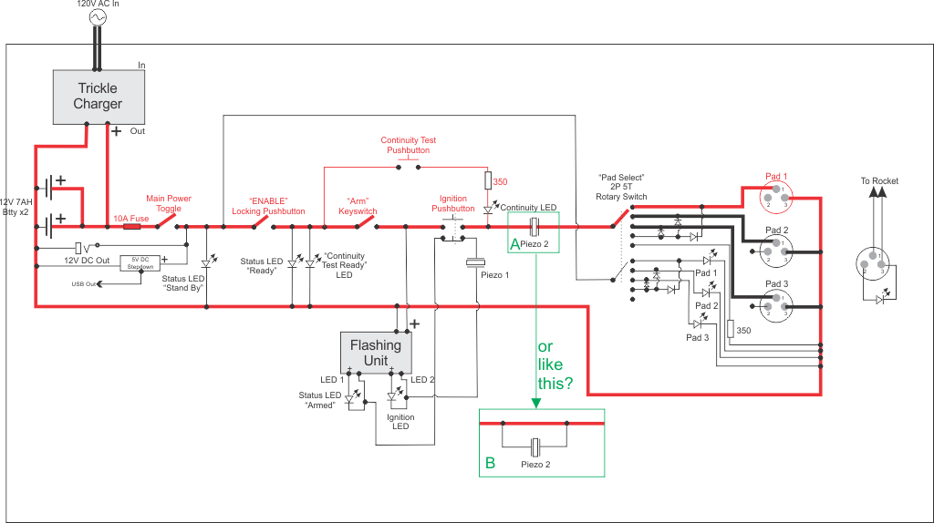
Which brings me to this nearly final schematic:

The red part is Phase 1. We do that first.
The thick lines are the high power circuit and 16AWG wire. Thin lines low power/22 AWG.
KaGbwqU.png


Which brings me to Piezo #2. (green boxes A and B) That's a low power device in the middle of the high power circuit, the leads on it are like 28 AWG.

So do I open it up and replace the leads??
or is B (or something like it) the answer?
 
Last edited:
I'm well ahead of you on all that (the features and the project phasing)


As well established higher in this thread I know nothing about wire gauge. However I am smart enough to read specs and ratings. XLR cables are designed for 24 volt systems, and rated for 50 volts. A typical mic cable can carry 48 volts of phantom power. I figure my 12 volts / 4 amps are safe.

Pricewise (assuming you want plugs on the ends of the wires and aren't just hardwiring in the cable) XLR cables can be cheaper than extension cords. This 25' mic cable cost $7 and has ends. Cutting the ends off a 120VAC cable and adding some connectors will cost more than $7 (and take time and effort).


Which brings me to a specific question:

What amount of power will set off a typical (Estes) igniter? (ie what is the max safe voltage for a continuity test and the min required voltage for ignition?)

Current, not voltage is what you need to look at. I designed my controller to supply up to 40 amps (at 12 volts) when firing and to limit the current through the continuity circuit to under 40 milliamperes.
 
As well established higher in this thread I know nothing about wire gauge. However I am smart enough to read specs and ratings. XLR cables are designed for 24 volt systems, and rated for 50 volts. A typical mic cable can carry 48 volts of phantom power. I figure my 12 volts / 4 amps are safe.

Not to get off track, but while XLR mic cables might be fine for this application, judging their suitability based on phantom power might be a misunderstanding. Phantom power sources supply only a measly 10mA per the standard.

Keep experimenting and enjoy the process!

Mark
 
Current, not voltage is what you need to look at. I designed my controller to supply up to 40 amps (at 12 volts) when firing and to limit the current through the continuity circuit to under 40 milliamperes.

Forgive my nomenclature, we are at the edges of my understanding of electronics. I can quote "Watts, times volts equals Amps" I understand that those numbers are transmutable in that fashion. But I can't really visualize what that means. I'm well aware of the plumbing analogy and how its also inadequate.

So both our systems operate at 12 volts.

you use 0.04 Amps for continuity testing and 40 Amps for launch. (my actual question was; where in there is the point of ignition?) Still that's useful information. How do you achieve that? There's a resistor in the circuit? What value?
 
Not to get off track, but while XLR mic cables might be fine for this application, judging their suitability based on phantom power might be a misunderstanding. Phantom power sources supply only a measly 10mA per the standard.

Thanks, good to know.

But I was basing it on their use in various professional 24VDC systems. Back stage lighting, winches etc. My high school gym had retractable bleachers that used these cables.
 
Forgive my nomenclature, we are at the edges of my understanding of electronics. I can quote "Watts, times volts equals Amps" I understand that those numbers are transmutable in that fashion. But I can't really visualize what that means. I'm well aware of the plumbing analogy and how its also inadequate.

So both our systems operate at 12 volts.

you use 0.04 Amps for continuity testing and 40 Amps for launch. (my actual question was; where in there is the point of ignition?) Still that's useful information. How do you achieve that? There's a resistor in the circuit? What value?

The actual point of ignition varies considerably; that’s why you have to provide a surfeit. It also depends on time. An igniter with 1 amp flowing through it might light in 20 seconds (that’s a made up number to provide an example) but might light in 1 second with 10 amps flowing through it. It will probably never light with 40 milliamperes flowing through it.
Devices such as electric matches have specifications for all-fire and no-fire currents that you need to design around. You design your controller to provide much more than the all-fire current but less than the no-fire current. Those ratings were designed to and then empirically tested by the manufacturers using a reasonable sample size. So for instance with ten matches they got none to fire below the no-fire current, but all worked the way they were supposed to at the upper rating.
Igniters typically require more current than ematches, but again, they will vary, not only between manufacturers but also between samples for a particular manufacturer.
“Watts, times volts equals amps” is wrong grammatically and physics wise. Watts divided by volts equals amps. The first thing you should do is really learn those equations and get very familiar with the various algebraic ways they can be stated.
Yes, I used resistors to limit the current during the continuity test. If you use Ohm’s law it’s very easy to calculate. V = i x r, or r = v/i. So, r = 12 volts divided by 0.040 amperes. That calculation yields 300 ohms. I used a 420 ohm resistor which keeps the current even lower.
 
Devices such as electric matches have specifications for all-fire and no-fire currents that you need to design around.
Exactly! and those numbers are.... ? or "they can be found ....(where)?"

Watts, times volts equals amps” is wrong...

Riiiiiiight: "volts times watts equals amps" (OK i can't quote it.)

You used an R420. thanks, I have R350s on order.
 
Exactly! and those numbers are.... ? or "they can be found ....(where)?"


Riiiiiiight: "volts times watts equals amps" (OK i can't quote it.)

You used an R420. thanks, I have R350s on order.

From the manufacturer, by doing experiments, or by googling and finding someone else’s work. Start by measuring the resistance of your igniters. Most igniters are somewhere around 1-2 ohms, which means that in a perfect circuit with a 12 volt power supply a 1 ohm igniter will pass 12 amps and a 2 ohm igniter will pass 6 amps. (Rewriting v = i x r as i = v/r). No more than that can flow due to Ohm’s law. The lower the resistance the greater the amount of current can flow. Every resistance will pass a specific current at a specific voltage assuming that current isn’t limited elsewhere in the circuit. That relationship is what ohms law describes.

And just so you know, my calculations didn’t include the forward voltage drop for the continuity LEDs or the resistance of the igniter but they would only result in even less current flowing.
 
From the manufacturer, by doing experiments, or by googling and finding someone else’s work....

Thanks but;
1. My first step in "googling" was asking my friends here on the Rocketry Forum.

B. I'm really quite surprised that you guys haven't already done a scientific study on this. Am I the first guy to ask to ask this question? (I'm sorry, I just came here from years of playing Kerbal Space Program, and on the KSP forums they would have already digested this information into 3 spreadsheets; cross referenced by manufacturer, price, and ignition temperature.)

So I'll go hunting on the big, wild, www. But isn't this part of an FAQ for this subforum?
 
Actually there is an excellent paper out there; that’s why I suggested googling. I could google it for you, but I’d prefer you do the work. I think you can find a link to it from one of the build your own igniter companies. Which I think you can find from Public Missiles. Search for “maximum current through Estes igniters.”

Edit: https://publicmissiles.com/IgnitersWhitePaperbyG-Wiz.pdf
 
I tried to read that. I have no idea what he's talking about

This page was more to my understanding:
https://home.earthlink.net/~david.schultz/rnd/igniter/neyer.html

He says the Estes igniters had an all fire at 4 amps
and the Quests (which fire at 1/3 of an amp) had a no fire at 130mA.

So (I think that means) I want an ignition current of 4 amps (or more), and a test current less than 100 mA.

Since you get the math, maybe you can help me figure out what's the actual maximum current I can get from these batteries.

I have 2 12 volt 7 Amp Hour lead acid gel batteries (in parallel)

And they say these numbers that I don't understand:
Cycle Use: 14.4~15.0 V
Standby Use: 13.5~13.8 V
Initial current: 2.1A MAX

Does that mean between the two batteries I have a 4.2 amps max??
 
I would not design a controller around a single type of igniter. If the igniter manufacturer decides to change their igniter (which Estes recently did) your system may have to be redone. You might want to fly a rocket on a CTI motor someday. Some of them use electric matches that have a low no-fire current, meaning that a continuity test using the numbers you quote for Estes no-fire could light a motor; obviously that’s a bad thing.
Instead, design it to have as little built in resistance as possible when firing and as low of continuity current as possible.
The last three lines that you copied describe the charging requirements of the battery. They are meaningless when it comes to how the battery works under load.
Those 12 volt, 7 amp hour SLA batteries can dump a pretty large current, well over 20 amps direct short terminal to terminal. The limiting factor is the internal resistance of the battery. You certainly don’t need to put two in parallel. I use a single one of those at each pad box in my system.
I’d be happy to help with the math.
 
Houston, we have beeping!

So I decided to start w/ the flasher circuit kit just to brush up on my soldering skills. It was a palm-sized bag of parts. That's all, not even a schematic (other than the printing on circuit board). It cost 99 cents with free shipping.

I haven't done any soldering in 30 years other than fixing a lamp now and then. Boy was that fun! I can honestly say I have never in my life had as much fun for 99 cents.

It's a little messy but totally functional. I don't think a 52 year old man ever giggled quite so much at two flashing lights. But adding the piezo didn't work. The flashing seems dependent on the current draw, and putting so much pull on one side, it never flipped over to the other side, just a solid "beeeeeeeeeeeeeeeeeee..."

But as I'm pinching wires together to test things, at one point one of the piezo leads comes loose, falls on to another exposed connection, AND BEEPS for just a second. It takes me a few moments to figure out I did. I put the piezo between the two sides. that worked. (I laughed like a mad scientist)

Which brings me to this nearly final schematic:

The red part is Phase 1. We do that first.
The thick lines are the high power circuit and 16AWG wire. Thin lines low power/22 AWG.
KaGbwqU.png


Which brings me to Piezo #2. (green boxes A and B) That's a low power device in the middle of the high power circuit, the leads on it are like 28 AWG.

So do I open it up and replace the leads??
or is B (or something like it) the answer?

You can't use Piezo #2 in either of those configurations. It has to be wired between +12V (output side of ignition push button) and ground (-).
 
Also remember that it is easy to short an igniter at the pad by mistake and your system needs to be able to handle that without melting or otherwise destroying itself. (No joke, I have seen model rockets catch fire from shorted Estes igniters connected to very robust launch controllers!)

I think what lots of folks here are trying to say is that building a fail-safe, robust launch controller with lots of features requires significantly more planning than building a single-pad, simple system, especially if you're designing for multiple pads.
 
I would not design a controller around a single type of igniter. If t
I'm not. My specs are specifically for a launch circuit above the high power Estes specs, and a test circuit below the low power Quest specs. (if I understand you specs, your 400mA test circuit could very well ignite a Quest igniter during the continuity test.)

You can't use Piezo #2 in either of those configurations. It has to be wired between +12V (output side of ignition push button) and ground (-).
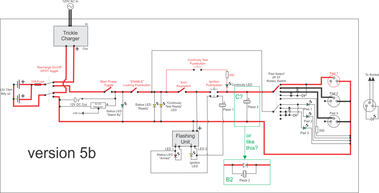
030j3Xo.png

(1st I think "A" would work for low power launches, I've seen it other schematics. But in my high power launcher i'd fry the piezo.)

Are you suggesting "c" above?
Doesn't that short out the continuity test? You'd get a light and a beep, regardless of the situation at the pad.

I thought of B2, the diode creates a V+ and V- for Piezo 2 and maintains the validity of the continuity test, but the buzzer is out of the way of the high power zap of ignition. right?

Also remember that it is easy to short an igniter at the pad by mistake and your system needs to be able to handle that without melting or otherwise destroying itself.
I'v got a 10Amp Fuse. Is that what you mean?

I think what lots of folks here are trying to say is that building a fail-safe, robust launch controller with lots of features requires significantly more planning than building a single-pad, simple system,
ajFsddN.jpg

"Yes, I know..."
:D
 
I'm not. My specs are specifically for a launch circuit above the high power Estes specs, and a test circuit below the low power Quest specs. (if I understand you specs, your 400mA test circuit could very well ignite a Quest igniter during the continuity test.)

No, my continuity check is limited to under 40 mA.
Are you ever going to want to launch a cluster with parallel leads?
 
(1st I think "A" would work for low power launches, I've seen it other schematics. But in my high power launcher i'd fry the piezo.)

Are you suggesting "c" above?
Doesn't that short out the continuity test? You'd get a light and a beep, regardless of the situation at the pad.

I thought of B2, the diode creates a V+ and V- for Piezo 2 and maintains the validity of the continuity test, but the buzzer is out of the way of the high power zap of ignition. right?

I'v got a 10Amp Fuse. Is that what you mean?

"Yes, I know..."
:D
The 1st one is it! No, you won't fry the piezo. C? will work; B2 won't! No, C? won't short out the continuity test. Yes, you will get a light and beep. If you use B2, you will only get the forward voltage drop across the diode to power the piezo, and besides, it doesn't make sense to do it that way.

I love the Fawlty Towers dig! Classic!
 
Back
Top