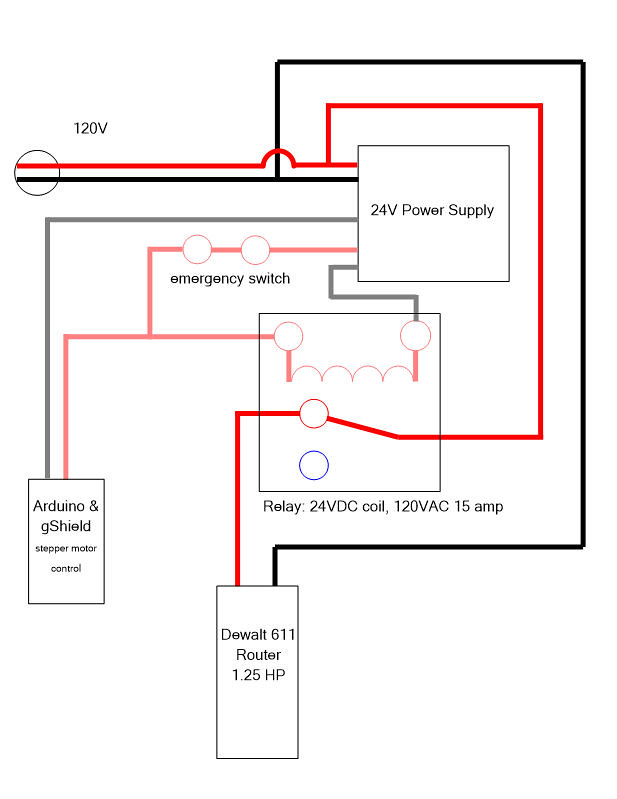
OK, so only loosely rocketry related, but as I'm moving through designing my home brew CNC router I want to incorporate an Emergency Stop. A full on the power is off NOW kind of switch. Because I have seen that the capacitors in the 24V power supply are capable of driving the Arduino and steppers for a few seconds after power is disconnected I can't just put the panic button on the line in. Also, I want the router to lose power simultaneously. This pretty much necessitates using a relay. This is unfamiliar territory for me, so I drew up how I envision this below. Advice from someone who knows what they are talking about is extremely welcome. Below is also a link to the relay I envision using. This I am even less sure about than the wiring, so advice welcomed here as well.
The schematics in the first post will work as intended, but I'd suggest doing it "backwards". Use a double-pole switch to fully disconnect the 120V line and use a relay with a 120V coil to disconnect the 24V line. The major advantage is, that it maximizes the scope of your emergency cut off. If your power supply starts smoking or, even worse, some error led to an electrocution hazard, a full disconnect of the system is the thing that you want to do.
As an added minor bonus, a power loss will lead to the same power down sequencing (but your power cord shouldn't be a tripping hazard in the first place ;-) ).
You DO NOT WANT A RELAY IN YOUR EMERGENCY STOP CIRCUIT, it adds a failure point.
This is standard industrial practice, although there are special "safety relays" used. Multiple emergency switches are often used for quick access from all directions. There are also safety interlocks, for example on things like access hatches. All these switches are usually connected in series and no matter which one is triggered, any potentially harmful source of energy (not only electricity but also pneumatic pressure etc.) is cut via the safety relay(s).
First off, thanks for the well thought out advice. I knew there would be several folks around here with the knowledge to advise on this.
1) I want the steppers to loose power NOW.
2) There are pins for limit switches for all three axis on the gShield, and I will use them for that purpose. I could wire in a stop button to these pins as well, and it would stop the steppers. In doing it this way I was trying to get the power shutoff to the router as a bonus.
If you really want to stop your steppers even harder and faster, you can short your steppers coils, as has been already mentioned. For a bipolar stepper, you need a double-pole double-throw (DPTP) relay. On end every coil, one end, lets call it 'A' gets directly connected to the stepper driver. The other end, 'B', gets connected to the "common" pin of the relay. The "normally open" (NO) pin gets connected to the stepper driver instead of 'B'. The "normally closed" (NC) pin of the relay gets connected to 'A'. Without power the relay, the motor is shorted and exhibits a much higher braking torque. You don't need additional resistors for this. The coils of the stepper motors will limit the current. You can play around with your steppers before you integrate them into your system. With open wires, you can usually turn the shaft with your fingers, with shortened wires you can't (depends a bit on the size of your motors). This active braking mechanism is, however, likely overkill and I would only consider them if you think your emergency switch does not stop it fast enough after some testing.
Sorry, I meant the router itself. They usually will spin for a few seconds do momentum.
In the most common error scenarios on a CNC mill ("Ooops, I didn't expect my program to do this"), it is advantageous if the axis drives stop before the spindle does. This will usually stop milling in a way that won't break your cutting tool. Scenarios were you want to stop the spindle as fast as possible independent of what the axis drives are doing are conceivable, but personally I haven't experienced them so far.
Reinhard


")
