Heat at Mach 2.25

The Rocketry Forum

Help Support The Rocketry Forum:

This site may earn a commission from merchant affiliate links, including eBay, Amazon, and others.

TZ250

Well-Known Member
Joined
Apr 15, 2010
Messages
300
Reaction score
2
Everyone,
About what temperature will different areas of my Kestrel see at Mach 2.25? I realize there are some variables involved, but all Kestrel's are close in size/shape/weight. (at least, close enough for this thread)

The math is complicated and most people use software to figure such things.

What do you think the nosecone, airframe at CG, and the leading edges of the fins will see at 1,750 MPH? 200 degrees? 300 degrees? (Fahrenheit)

I'm just curious. TIA.
 
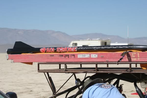
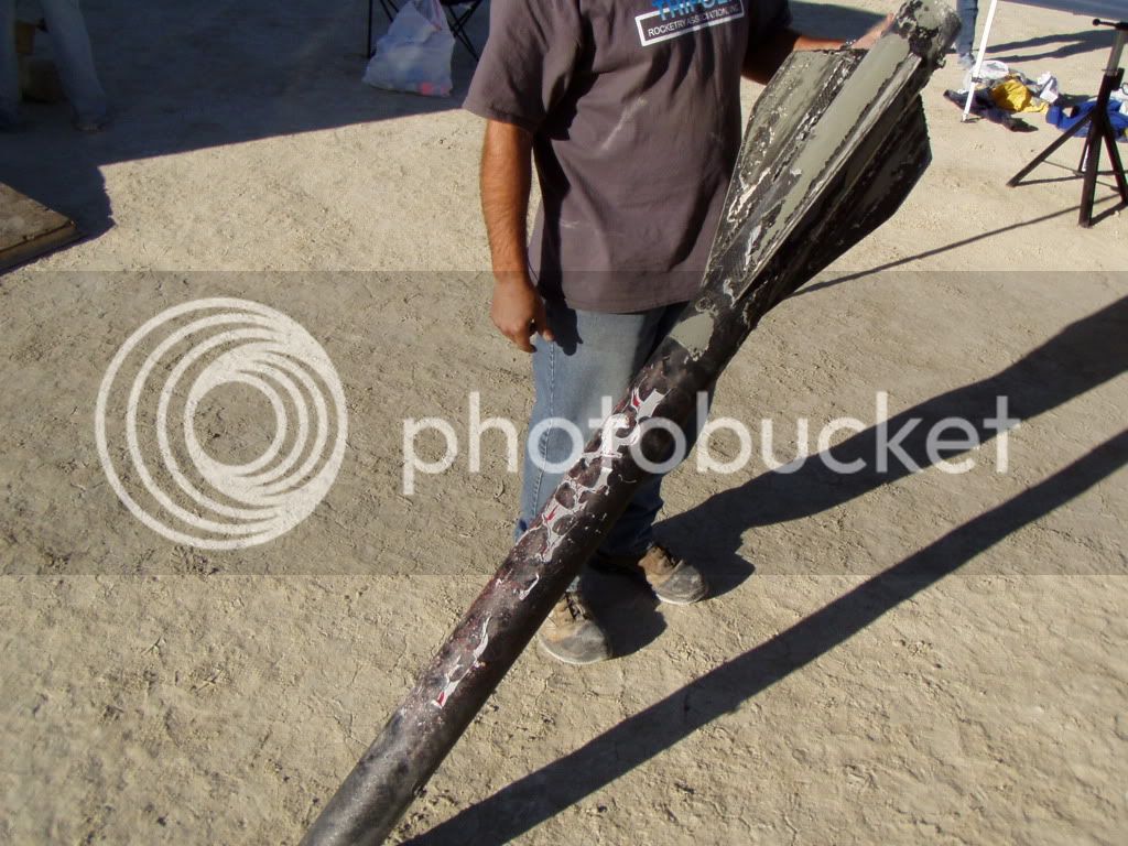
Here's a view of what it might look like after the flight (if it survives).

Before:
IMG_1159.jpg


After flight:
P1010053.jpg


Pictures by Scott Kormiere & David Reese.

Can also be found here:

https://tqc.yuku.com/topic/3278?page=4

The rocket is all carbon fiber & is owned by Ed Enyart powered by a 98mm O motor.
It killed the R-DAS tiny & pulled well over 50 G's.

JD
 
Last edited:
Yikes! What are you going to put in there to push it over Mach 2?

A CTI L935. John Wilke, from 3 Dogs Rocketry, designed the Kestrel to fly on K's and L's (hence the name KestreL). It will be fast, but not super fast.


I'm just curious about the heat.

JDCluster, thanks for the cool photos and link!
 
It killed the R-DAS tiny & pulled well over 50 G's.

JD

Use a Raven. My L3 flight did 54 G's without blinking.

A CTI L935. John Wilke, from 3 Dogs Rocketry, designed the Kestrel to fly on K's and L's (hence the name KestreL). It will be fast, but not super fast.


I'm just curious about the heat.

JDCluster, thanks for the cool photos and link!

Sweet. I should be flying mine on that and the L640DT at LDRS.
 
Rob,

While I don't have a Kestrel, an all carbon 75mm bird that I flew to Mach 2.2 melted the clearcoat on much of the nosecone and portions of the fins. The clearcoat is supposedly rated to 500 degrees F.

-Eric-
 
John (3-Dogs) flew his Kestrel on an L935. Pretty much a stock kit, IIRC. He posted some results on RP. (K300 v.s. L935 v.s. L640 - all flown the same day; same rocket).

Jeroen
 
When I flew my 2" rocket on L730's, the nose cone would regularly look like the picture below. The speed with this motor would be right at Mach 2. I tried some higher temperature paints from the big box stores, but didn't find anything that worked. Now, I paint my high speed nosecones with the Cotronics/Duralco 4525 epoxy, and that seems to work pretty well. I have noted that the "regular" fiberglass nose cones from Performance Rocketry can bubble a little under this epoxy, but it is certainly better than paint. The "graphite" cones plus contronics survive unscathed, at least up to Mach 2.6 for short durations.

Painting with this epoxy is a little like trying to paint with cottage cheese - it's not really designed for the job. However, it can be done, and with a little technique and a lot of sanding, the results can be pretty good.

I also paint the leading edges of the fins with cotronics. I have never seen the epoxy itself fail, but it wouldn't surprise me if the underlying epoxy would degrade over multiple flights.

Jim

Shocklet Nosecone.JPG
 
Last edited:
Everyone,
About what temperature will different areas of my Kestrel see at Mach 2.25? I realize there are some variables involved, but all Kestrel's are close in size/shape/weight. (at least, close enough for this thread)

The math is complicated and most people use software to figure such things.

What do you think the nosecone, airframe at CG, and the leading edges of the fins will see at 1,750 MPH? 200 degrees? 300 degrees? (Fahrenheit)

I'm just curious. TIA.
You're asking the wrong question.

The math is not that difficult, but the real question is what is the heat load and how will the NC and the leading edges handle it. (The airframe doesn't get hot.)

The heat load is proportional to the product of the air density times the Mach Number cubed. You need to perform a trajectory calculation to develop a time, velocity, and density table to determine the cumulative heat load versus time, and then look at the mass per unit area, the specific heat capacity, and thermal conductivty of the NC and leading edge material to determine the temperature history of the surfaces.

Bob
 
John (3-Dogs) flew his Kestrel on an L935. Pretty much a stock kit, IIRC. He posted some results on RP. (K300 v.s. L935 v.s. L640 - all flown the same day; same rocket).

Jeroen

YIKES. That sounds like a very tiring (and expensive) day.
 
When I flew my 2" rocket on L730's, the nose cone would regularly look like the picture below. The speed with this motor would be right at Mach 2. I tried some higher temperature paints from the big box stores, but didn't find anything that worked. Now, I paint my high speed nosecones with the Cotronics/Duralco 4525 epoxy, and that seems to work pretty well. I have noted that the "regular" fiberglass nose cones from Performance Rocketry can bubble a little under this epoxy, but it is certainly better than paint. The "graphite" cones plus contronics survive unscathed, at least up to Mach 2.6 for short durations.

Painting with this epoxy is a little like trying to paint with cottage cheese - it's not really designed for the job. However, it can be done, and with a little technique and a lot of sanding, the results can be pretty good.

I also paint the leading edges of the fins with cotronics. I have never seen the epoxy itself fail, but it wouldn't surprise me if the underlying epoxy would degrade over multiple flights.

Jim
The Cotronics 4460 resin is a good laminating resin (low viscosity) that has excellent high temperature properties. It is a light amber clear reasin instead of the black 4525 which has a higher viscosity. https://www.cotronics.com/vo/cotr/pdf/4460.pdf

I'm fairly certain it is a Bisphenol-F resin system. This resin system can take massive heat fluxes for durations that are typical of high performance hobby rocket flights. These resins are use in G10/FR4 commercial composites and will char but not blister.

Bob
 
Hello,
Ouch that looks bad ,especially the dimples in the carbon fiber of Ed Enyart rocket,unless that was caused by the landing.

Hitting mach 2 at such a low altitude definitely creates alot of heat.
Not to mention the massive G applied to the vehicle.

Your Max Q pressure must be incredible.

Is there any way you go with less thrust but a longer burn ,so you hit mach 2
at a higher altitude with less air density?

Not to mention reduce the electronic chip killing G forces.

Btw What about auto exhaust paint ,most of them are rated to 1000deg F

Greg

i heard of a two stage single motor, started with a slow long burn, and then reached a certain time and hit an extremely high thrust point which pushed the rocket extremely fast. can't remember if it was solid or hybrid, but it allowed high mach at higher altitudes that didn't apply as much heat to the exposed areas.
 
Last edited:
i heard of a two stage single motor, started with a slow long burn, and then reached a certain time and hit an extremely high thrust point which pushed the rocket extremely fast. can't remember if it was solid or hybrid, but it allowed high mach at higher altitudes that didn't apply as much heat to the exposed areas.

That would be very cool. CTI makes the only dual thrust motor that I'm aware of, but the thrust starts out high then it's drastically reduced.


Thank you everyone for the excellent information. I'm having fun and learning at the same time! :)

https://www.thrustcurve.org/simfilesearch.jsp?id=1619

Image from www.thrustcurve.org
simfile1619_650x350n.png

There are several dual thrust motors available - from CTI there's the L640 that you mentioned, along with the much larger M1300, and from AT, there's the K375NW, as well as the I59WN.
 
The stagnation temperature, To, for a perfect gas is readily available from any compressible flow book (I like Shapiro). The formula is

(To/T) = 1 + .5 (k-1) * M^2

Where is

T = ambient temperature on an absolute temp. scale (for example 70 Deg.F. is T = 460 + 70 = 530 Deg.R.)

k = specific hear ratio = 1.4 for air

The results from this formula should be close to the NASA calculator. This is the upper limit (adiabatic) for the gas temperature. Because heat is conducted to both the vehicle solid surface and the surrounding air, the peak air temperature will be lower. A common way of handling this (rather than using the more complicated CFD) is to use a Recovery factor. Just multiply the Total temperature by something between 0.85 and 1.0 (There are formulas for finding Recovery factor). Now, to find the heat flux to the wall you need a heat transfer coefficient (use something like Reynold's analogy) and the solid wall temperature. The heat flux to the wall will be the heat transfer coefficient times the film temperature difference(gas temperature minus wall temperature). In general materials that HPR modelers use (fiberglass, epoxy, etc.) are like insulators. At first the wall temperature is relatively cold, so the wall surface temperature goes up quickly because the heat does penetrate into the solid very quickly (the material is like an insulator because of the solid's low thermal conductivity). The integrated heat load is not very much, because the rocket dwells at supersonic speeds for very short times. Hence, surface effects are noticeable, but in-depth effects are not substantial.

The heat transfer coefficient using Reynold's analogy is high at the nose, because the B.L. is thinnest there. As the flow goes down the side of the vehicle the B.L. becomes thicket and the heat transfer coefficient goes down.

Bob
 
Last edited:
In general materials that HPR modelers use (fiberglass, epoxy, etc.) are like insulators. At first the wall temperature is relatively cold, so the wall surface temperature goes up quickly because the heat does penetrate into the solid very quickly (the material is like an insulator because of the solid's low thermal conductivity). The integrated heat load is not very much, because the rocket dwells at supersonic speeds for very short times. Hence, surface effects are noticeable, but in-depth effects are not substantial.

One exception is carbon fiber, which is quite a good conductor in the direction of the fibers. I think carbon's ability to conduct heat away from hot spots on the surface is an advantage in high-speed flights. In particular, the leading edges of my carbon fiber fins came through a Mach 2.5 flight unscathed, despite the fact that the fins were only 0.045" thick.
 
This could be. When I listed insulators I did not list carbon, because compared to good insulators, carbon is a heat conductor. On the other hand, compared to metals, carbon is probably an insulator. When calculating an in-depth temperature, one must also consider the heat capacitance of the solid, too. Carbon being a solid will have a much higher capacitance than the surrounding air, so the rise in the average temperature will be lower than the surrounding air.

Bob
 
HTML:
 I did some research and found a dow corning 2 part rtv that is an ablative.
Dow corning 3-6077 RTV Silicone Ablative with penetration rate 0.035 mm/sec
at 45W/cm2 (approx 40 BTU/ft2-s).

This is one way of looking at solid heat transfer problem. Although, one should be careful about talking about ablation versus the temperature profile diffusing into the solid by conduction. The rates might be different. Some materials may ablate or erode directly from the solid phase to the gas phase. Other materials like silica phenolic or carbon phenolic will form a char layer (where the volatiles, etc. have cooked out) that blows or erodes away. This is the case in phenolic nozzles for large solid rocket motors. So, the ablating part is different than the heat conduction. The rates are different. Behind the char layer, heat diffuses into the virgin phenolic by ordinary conduction. Actually, carbon phenolic has not only been used in solid rocket motors, but also on re-entry heat shields.

One also can talk about the rate of heat diffusivity into the solid by conduction. One approximate way to do this is to use the method of Goodman, where one assumes a parabolic temperature profile diffusing into the solid. One could probably come up with an estimate of how fast the temperature profile advances into the solid. If the thermal conductivity of the solid is high and the thickness of the solid object is small, one can check the Biot number and say that the temperature profile is essentially flat and that the temperature of the whole solid changes with time uniformly. If this were the case for thin fins, one could estimate that all the thermal energy in the gas thermal B.L. could be in equilibrium with the thermal energy in the solid. For our kind of problems, the rise in the carbon fin temperature might not be too bad, because the thermal capacitance (density times thermal capacitance) of the solid might be on the three orders of magnitude higher than the gas. (Solids are much denser than gas.)

Bob
 
There are several dual thrust motors available - from CTI there's the L640 that you mentioned, along with the much larger M1300, and from AT, there's the K375NW, as well as the I59WN.

It wasn't a dual thrust motor in the general sense since all of the dual thrust motors above are boost sustain, the one i saw was more of a sustain-boost motor :O
 
Hello,
While I agree with bob ,That the heat flux to the carbon fiber is short enough
in duration that it isnt a problem.
There is one little problem ,that is that the heat is boiling the volatiles of the epoxy off before the carbon fiber reaches its charred state.
While the carbon fiber itself is not damaged the epoxy that is maintaining its
fixed structure it rapidly being ablated.
You will then see softening of the nose cone due to the stagnation temperatures of high mach at low altitude or possible structural failure.

Greg
 
Hello,
I did some research and found a dow corning 2 part rtv that is an ablative.
Dow corning 3-6077 RTV Silicone Ablative with penetration rate 0.035 mm/sec
at 45W/cm2 (approx 40 BTU/ft2-s).

https://www.specialtyadhesives.com/dow_sealants/3_6077_RTV.pdf

Greg
For comparison, a flight like ExSSugarShot must hit Mach 5+ if it is to go 100+km apogee. The peak heat load is ~45 W/cm2 at ~40kft, and the total heat load to the NC and leading edges is 400 W-s or Joules. This is about the minimum velocity where you can take advantage of ablatives.

Bob
 
Hello,
While I agree with bob ,That the heat flux to the carbon fiber is short enough in duration that it isnt a problem.
There is one little problem ,that is that the heat is boiling the volatiles of the epoxy off before the carbon fiber reaches its charred state.
While the carbon fiber itself is not damaged the epoxy that is maintaining its fixed structure it rapidly being ablated.
You will then see softening of the nose cone due to the stagnation temperatures of high mach at low altitude or possible structural failure.

Greg
There are no "volatiles" in professional phenolic epoxies to boil off. Phenolic epoxies have a graphitic type backbone, and when it gets extremely hot, well above 350C, the resin pyrolizes which means it looses OH and H radicals as it converts to char (graphite). Pyrolysis of phenolic epoxy will not occur in s short M=2.25 rocket flight as the temperature of the resin won't get that high. Paints however will blister under under this level of heating.

Bob
 
There are no "volatiles" in professional phenolic epoxies to boil off. Phenolic epoxies have a graphitic type backbone, and when it gets extremely hot, well above 350C, the resin pyrolizes which means it looses OH and H radicals as it converts to char (graphite). Pyrolysis of phenolic epoxy will not occur in s short M=2.25 rocket flight as the temperature of the resin won't get that high. Paints however will blister under under this level of heating.

Bob K.,

Sure, I agree. "Pyrolysis" is the correct term, but in any case the advance of the char layer (which involves ablation, erosion, etc.) is different from the advance of the temperature profile by heat conduction.

Bob M.
 
So should the nose cone and fins be left bare on Mongoose and Black Hawk rockets ?

well you "can" paint them, but if you're going to hit above mach 2 or so for even a short time, they're gonna look kinda funny with the blistering. But really, if you're going for maximum speed, no paint, adds weight, just sand to an amazingly smooth finish :)
 
I am surprised that no one has suggested looking into the paints that were used on the XB-70 or SR-71. Both of those planes would spend a considerable mount of flight time at or above Mach 3.0.
 
Back
Top