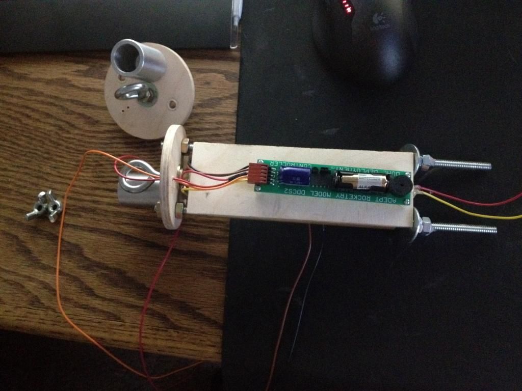
how to connect fetherweight magnetic switch to DDCS2

The Rocketry Forum

Help Support The Rocketry Forum:

This site may earn a commission from merchant affiliate links, including eBay, Amazon, and others.

Inerax

Well-Known Member
Joined
Aug 15, 2011
Messages
169
Reaction score
1
Hello everyone. After taking a short break from rocketry to purchase a house its time to start again.

I have a 3 inch DD rocket i am going to fly as my level 2. It is also going to be my first DD rocket. I have not decided if I am going to do my first DD and L2 test on the same launch.

I am looking at getting one of the Featherweight magnetic switches.

Leading from the the altimeter I have 2 red, 1 orange and 1 yellow that connects to the charges.

I then have the brown and black that when connected they activate the altimeter.

What lines would be running to the switch to activate the altimeter?

Thank you everyone!
 
Brown and black, if I understand your description correctly.
 
Check out Quaranta's post titled "Blackhawk 29 Dual Deploy Build Thread". It starts at post #84 and shows how he used the magnetic switch in his set up.
 
Check out Quaranta's post titled "Blackhawk 29 Dual Deploy Build Thread". It starts at post #84 and shows how he used the magnetic switch in his set up.

That is a great diagram but i am still confused :(

My adept has the battery built in so how do I bring the power to the switch?

I see that he has the battery direct into the switch.

altimeter.jpg
 
Last edited:
From the DDCS2 Instruction Sheet:

The BLACK wire and BROWN wire connect to an On-Off switch, or some other gimmick for completing a connection between the two wires. A non-elegant but very effective way of making the connection is to simply twist the two wire ends together. Before power up, these wires can simply hang out a hole in the rocket body, such as one of the static ports. After twisting the ends together, fold a piece of masking tape over the exposed ends to electrically insulate them, then push them back inside the rocket body.
===
If I recall, the third connection on the Magnetic switch will go to ground, as it will use power from the switched connection to power the switch electronics. I've looked at the documentation I can find online and I can't find where the pinout is documented other than whats shown above. A guess would be the two RED wires in the center that go to one pin. However red is not usually used for ground... so I would want to check my theory with a multi-meter before connecting.
 
Back
Top