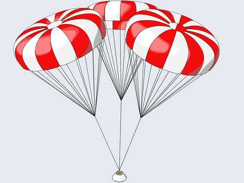
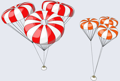
Apollo LES 4"

The Rocketry Forum

Help Support The Rocketry Forum:

This site may earn a commission from merchant affiliate links, including eBay, Amazon, and others.
Typico, I forgot: why don't you post about your Speedweiser in the HPR section of the Forum?

I'm sure people would love it!!!

youre right, one thing to do in early future

did you see my email?? i solved my problems with rhino so no need of answere anymore

but i have a question about unalighed boosters...
i send you an email right now, hope to see your reply soon!!!:D:D
 
Now, that is too flimsy to fly, I'll add some glass from the inside before joining it to the CM. The final weight will increase but I already saved a lot!

Ok, I left you with the flimsy heatshield: it went from 2560 grams down to 635 and it turned out even lighter (570 grams) as I spent some more time sanding off the excess resin here and there.

Now, it is flimsy because I covered it with a SINGLE layer of heavy cloth: The capsule got 4 layers and it survived a brutal de-molding!

So I added 2 internal layers of 200 gr/mq fiberglass cloth in the form of overlapping triangles between the wooden spiderweb:

3512833285_8acb3fbfc6.jpg


I also drilled a lot of perimetral holes along the remainings of the base ring to promote epoxy adhesion:

3512833209_a27d10949f.jpg


As you can see the final weight rose to 826 grams which sounds like an acceptable trade-off in the end.

I also got the capsule interiors ready for joining: a lite-ply ring was added and drilled, I cleaned the skin from glue residues and I trimmed the forward wooden frame I left as much as possible:

3512833369_f208347233.jpg


The capsule and the heatshield are now permanently and happily joined together to form the first flying capsule in the program!
 
Now the capsule isn't finished yet but I need to move onto other working areas prior to its completion.

Remember the Booster Skirt Mold (post #67 - page 3)?

I got the first skirt...

3512833829_1420394ef0.jpg


... raw out of the mold...

3512834057_ba8fafc179.jpg


... and trimmed (view from the inside):

3513641520_c3cc249304.jpg


The openings are for the 4 launch lugs and for the 2 sets of external wire channels:

3528296144_f612fa42b2.jpg
 
I got back to the booster section...

3011841587_280a119b94.jpg


... and I added the skirt base-plate (1/4" lite-ply) and the fillets:

3512833763_1080679df0.jpg


Launch lug openings are next...

3513641356_97003a1f2f.jpg


... as well as the launch lugs themselves with hefty fillets:

3512834155_db27ac5eb4.jpg
 
Booster Protective Cover

That's all is missing to complete the booster section!

Using the capsule plug I laminated a sandwich of

. 1 layer of heavy f/g cloth

. 1 layer of 1/8" thick absorber

3490172197_47b1d01a89.jpg


. another layer of heavy cloth

to obtain a very raw-looking BPC:

3490172469_efaa37e683.jpg


The absober choice is stupid: not only it adds unwanted weight but it also leads to a weird finish!!!

The de-molded BPC...

3490172509_7224518381.jpg


... trimmed:

3490172541_3b7b64bcca.jpg
 
Some sort of 'seat' for the airframe tubing is routed on the exterior of the BPC...

3513640458_5c342b873c.jpg


... so that the entire airframe can be joined checking for the correct alignment between each section:

3513640510_abdd4ab8f3.jpg


The epoxy joint isn't enough: an external reinforcement is required in the form of overlapping fiberglass strips; I also added an extra skin layer (light cloth) for a better finish...

3512833453_1a77166f01.jpg


Two coats of 2-pack automotive (yet lightweight) filler were added...

3513640974_72eb923b42.jpg
 
Last edited:
... and smoothed out with a belt sander (80 and 120 grit)!

3513641028_d94bb03bbb.jpg


You got it: the absorber thing on flying objects isn't a big deal at all!

The BPC tip inside the airframe is useless...

3512833521_0a31145034.jpg


... and it was removed:

3513641078_80abd4db5f.jpg


At this point the booster skirt can be glued in place to lead to the (almost) completed booster section:

3512834293_5949eb2df9.jpg
 
Last edited:
The last hassle deals with both the booster section and the capsule: we need to route the launch rods inside the capsule via some pretty long launch lugs (aluminum tubing).

I transferred the rod openings both to the capsule tip and heatshield:

3512834351_628d69ec9c.jpg


3512834401_584e43a913.jpg


It is better to glue the lugs to the heatshield first: join the booster section to the capsule, slide the lugs in place with the rods inside and turn everything upside-down:

3513641814_56e89b99db.jpg


I used blobs of epoxy to secure the lugs as the openings I drilled were larger:

3513641872_de43114e76.jpg


It is really important to work with the entire assembly together and the rods in place to grant for the alignment between each length of the lug!
 
Now, the lug-tubes won't stay where they belongs until you glue their top ends as well: use plenty of epoxy again...

3512832967_335bdc5ab9.jpg


... but mask the exposed area...

3513641926_1b628ab485.jpg


... so it won't stick to the BPC! Why? because you need to re-assemble everything together and let it cure upside-down with the rod inserted!

3513641814_56e89b99db.jpg


Now it is a simple matter of tirmming and sanding the lug-tubes flush with the skin:

3533499636_754e0e99ec.jpg
 
Every time you post, I am more and more humbled and revert back to RTF projects for a time.

It looks great.
 
Views of the capsule during these finishing days:

3533499668_7615383974.jpg


3532681483_a8c44c6ca8.jpg


3533499564_31077bd741.jpg


The other sections are being dressed up as well:

3533499720_c314b4377d.jpg
 
Last edited:
As I'm pretty close to completing the first phase of the program... ehm... project I end up this update with 2 pictures I tailor-made for the topic:

"The anatomy of the vehicle"

3532379731_09f79dabeb.jpg


3527485437_bee6f81838.jpg


3527485469_b0f66e1501.jpg


The simplified flight-profile of the first mission

3530628493_ff93ec464b_o.jpg
 
Giacomo,

Looks wonderful!

When do you anticipate the first test flight?
 
Hi Steve!

I got the 4 Pro38 3G cases, I'm getting the reloads as well (I170 Classic propellant) and I'm working hard onto the finish.

I guess by the end of June, I'm not working at the moment, I'm searching one, so much of it depends on how things evolve in the next weeks. This is why I'm pushing so hard right now: I'm still free...
 
CM Recovery System

I worked hard onto the finsh and I sprayed a huge amount of white paint... Now, while the paint dries for at least a week I'm working onto the final designing challenge of the project: the capsule recovery system (for the next generation of flying capsules).

This is going to be a tough task as I'll show you. I started with a classic Apollo recovery picture: it helped me scale both the canopy diameter and the distance between the canopies and the CM attachment point.

It turned out that:

. the diameter of each chute is 122" = 310 cm

. the distance is 615 cm

3551302122_a618e4019f.jpg


The following pictures models 3 120" fruity chutes (16 gores) at the scale distance from the CM: not bad if we consider that each 120" is rated for a 50 pounds load while the CM weights 4 to 6 pounds!!!

Please stop laughing!

Second and alternate design involves 3 60" fruity again (12 gores) at the same scale distance from the CM:

3550494101_3ddce7806b.jpg


There's little I can do with it. I read the Apogee Newsletter # 187 dealing with parachute clusters in the hope of getting some knowledge and find some sort of inspiration.

I hope you don't mind if I sum things up a bit:

Parachute clusters

1. all the chutes in the cluster must be identical (obvious but worth saying)

2. not all the identical chutes inflate at the same time:

. the first one inflating "bear the worst of the opening shock" and blanks out the other chutes

. there's no way to know whichever chute will inflate first (so they all need to be strong enough to inflate first)

3. inflated chutes "fly tipped over at some angle of attack instead of flying directly over a payload like a single chute does"

. they do interfere with each other leading to a certain degree of drag loss (God only knows how much) plus they're less efficient at such high angle of attack

. angles are higher as the payload weight gets lower

4. some geometrical features need to be checked to make sure the systme will perform fine.

Let's get into details.

4. some geometrical features need to be checked

The Effective Rigging Length (ERL) is "the distance between the payload attachment point and the skirts of the chutes in the cluster when the recovery system is stretched out flat".

The ERL is a minimum value and it helps reducing "the amount of interference between the chutes in a cluster".

ERL = square.root(n)*D

where n is the number of chutes in the cluster and D is their inflated diameter. Quite simple, let's check it using the project as an example:

3551194511_dafcce51f7_o.gif


Let's consider the 120" 3 chutes cluster configuration:

ERL_120 = 1.73*(120*2.54) = 528 cm = ERL_120 , the yellow line.

Those 528 cm do include the projected shroud line length (red line) equals to 315 cm: the required shock cord length to get the minimal ERL is then given by

528 - 315 = 213 cm (blue line)

The more shock cord you add the better behaviour you get in terms of
Forebody Wake Effect (FWE): "basically the air flowing past the payload (forebody) produces a wake which can interfere with the chutes, dropping their drag by as much as 25%".

Now

. the ERL accounts for chute-to-chute interference and consequent drag loss

. the FWE accounts for payload-to-chute cluster interference and drag loss

It seems to me that FWE is more critical for the 60" canopy config than it is for the 120" version: the bigger canopy catches more air than that the CM actually shields!

IOW, the smaller the canopies the bigger the CM will be (with respect to the canopies themsleves), the more the shadowing effect, the longer the lines to avoid FWE.

That is automatically achieved by leaving the same CM to canopy distance (which is a scale length) regardless of canopy diameter!

Moreover, I think that some kind of math law should be needed to compute the required anti-FWE length in terms of the parameter payload dia-to-chute dia ratio: the lower the ratio the higher the length, that would make sense!

i.e.

CM is 24", each canopy is 60" thus param = 60/24 = 2.5 == more critical

CM is 24", each canopy is 120" thus param = 120/24 = 5 == less critical
 
Last edited:
Now let me introduce the CM internals!

3550494069_4b8768ab3e.jpg


3550494139_dcb19cfe48.jpg


That's a 4" airframe tubing housing

. the recovery electronics

. the tower release device

. the black powder can that fires the tip and the pilot chute

Around the 4" tube I designed 3 main compartment sectors that offers the largest volume available for the chutes themselves.

2. not all the identical chutes inflate at the same time

Let's try to figure out what could happen:

1. the CM releases from the tower and reaches the apogee, the BP charge fires and eject the tip and the pilot:

3551301998_f84f020bf4.jpg


2. the pilot inflates and starts to pull the mains out of the CM:

. each main is bagged inside its own deployment bag

. the mains deploy one after the other instead of all at the same time: this way the system favours what usually happens instead of fighting it!

3550493931_d43b8634ca.jpg


3. all the bags out of the CM, chute #1 out of its bag and starting to inflate:

3551302044_e6e5fb0fa1.jpg


4. all chutes inflated, CM tip and bags hanging from the pilot on their path to the ground:

3550493979_d9e70fca58.jpg
 
Giacomo,

I would be concerned that the capsule may not weigh enough to pull open 3 120" chutes. If the capsule weighed 75 pounds :eek: yes. But <5 pounds, I think you might have a problem.

The first couple of times I flew my pad abort I used 3 x 18" nylon parachutes. The nice thing about that big long escape rocket is that it can easily hold 3 chutes. The escape rocket is so long the chutes just need to be rolled up (without any folds between the apex and base). I did not have any problems but have since switched to 2 X-form chutes made by Mrs. Sandman.

I really like your idea for the capsule chute deployment.

Steve
 
Last edited:
Giacomo,

I would be concerned that the capsule may not weigh enough to pull open 3 120" chutes. If the capsule weighed 75 pounds :eek: yes. But <5 pounds, I think you might have a problem.
Yes of course!

3. inflated chutes "fly tipped over at some angle of attack [...]"

. angles are higher as the payload weight gets lower


This is what may give the impression that larger-than-required chutes could be employed. As the payload weight decreases the chutes automatically tip over to a greater angle of attack thus reducing their Cd: this leads toward a new equilibrium in the ultimate attempt to allow the entire system to... descent!!!

3551273029_362a266f9d.jpg


Is it feasible? We can expect that the system would fail if the chute dia grows beyond a certain point: the new equilibrium state may be found by the system itself in a 'different' configuration in the form of

. non inflated chutes whose drag is enough to recover the payload for a given (low) weight

. collapsed chute(s)

. tangled system

What to do?

My original idea was to artificially lower the chutes' Cd by

. enlarging the spill hole (again, beyond certain boundaries)

. replace rip-stop nylon with meshed material that filters the air rather than catching it

but still, packing the 120" low-Cd chutes could pose some problems.

At the time being I'll see what's the biggest standard chute that can be packed in the sector, then I'll model it and see if it simply lloks fine: mods will then be considered to lower the Cd even more and flight testing will determine if the less-efficient-behaviour helps with the rest...

Stay tuned!
 
Last edited:
If you want to you could integrate some removable ballast to bring the weight up. If you have 4 38mm MMT you could use some higher thrust motors and bring the weight up to about 25lbs so you could use 3 scale 120" chutes. I think it would be a cool feature/affect and should try and be integrated. If not try some 108" chutes. They would be slighty smaller but just as affective and you would never know (ok YOU would!)

Ben
 
Well...if you can not fire individual poilot chutes in opposite directions, sequential deployment, as you proposed, is probably a good way to go.

Think Gus makes a good point on weight.

120"...looks nice and scale...but oh boy those are BIG chutes.
 
. replace rip-stop nylon with meshed material that filters the air rather than catching it

Here it is what I mean:

pilotchutesnew.jpg


that's a base jumping pilot chute, they replace the shroud lines with meshed fabric to avoid tangling: now, that meshed fabric could be used for the canopy and I think it would decrease the Cd dramatically.
 
Hi Giacomo, now this is a cool project and thanks for separately contacting me.

I do agree that trying to inflate three 120" of our chutes is going to be tough unless the weight is substantial. This combination is rated at 150lbs @20 FPS. I do agree with a previous post saying that something in the neighborhood of 50lbs would also do a better job loading the chutes.

We don't have any sort of mesh fabric that is going to work that I know about now, I will check with my wife who is the seamstress. As I recall most mesh is pretty stiff and bulky. I'm thinking of the kind of mesh used on dresses, and usually polyester, or some kind of knitted fabric. I am just winging this a bit since I am not that familiar with these fabrics.

Your idea of using three 60" chutes would be closer to releasable although maybe not scale.

---

On deployment I think you want to pull out all three chutes in parallel. In conversations I've had with Eric Gates regarding multiple chute systems there is a real possibility that if one chute inflates first, the next one can easily get tangled into the shroud lines of the first. So dragging all three out at once, and parallel inflating these is the way to go. Just my opinion. In multi-chute projects we have done for other customers this has always worked.

---

Cool stuff, hope this helps... :)

- Regards

Gene Engelgau
KI6IBL, NAR 86770 / TRA 12243 - L3, Lunar# 1468, CA PIII, LEUP
https://fruitychutes.com - Custom Parachutes in Fruit Flavored Colors!
 
Last edited:
Your idea of using three 60" chutes would be closer to releasable although maybe not scale.
Thank you Gene for dropping in!

I'm fine with your suggestion about parallel deployment, it makes sense and it is easier to do as the pilot is attached to the 3 bags with the same length of shock cord.

One last thing: could you please tell me what is the biggest custom chute we could pack inside the CM sector?

I think it is something more than a 60" and that would help a bit with the scale appearance!

The theta=120° sector volume is given by:

. id = 4.72" inner diameter (12 cm)
. od = 10.24" outer dia (26 cm)
. rl = 2.75" radial length (7 cm)
. d = 11.8" depth (30 cm)

so that the area and the volume equal respectively

A = pi*((od/2)^2-(id/2)^2)*theta/360° = 21.58 sq.in.

V = d*A = 255 cu.in

That's the packing volume available for each parachute, and I'd like to employ a bag as you already know.

Please note that the packing volume isn't exactly cylindrical.
 
Last edited:
I am not sure how tight thow fruity chutes pack but you might be able to fit those 120" in 255cu/in. I know atleast 96" chutes.

Ben
 
Three 120&#8221; chutes seem huge for a 5 pound rocket.

Even one 120&#8221; chute seems to be larger than necessary.

Yes there is a bit of loss by the chutes tipping over, but still, it is not that drastic.

The shadow effect of the CM is irrelevant for something like this, at least regarding descent rate once even one of those chutes opens, so that has no bearing on choosing chute size.

What to do?


Well, years ago I flew my Little Joe-II with a simulated Command Module inside of it, which had three 10&#8221; chutes on it. The CM was sort of light, maybe an ounce, maybe a bit less than an ounce. I had test flown it and it came down pretty slow, slower than the rest of the model did, so it landed last. Then when I few it at the actual contest, the CM hit a thermal ,and FLEW AWAY!

So, the efficiency loss is not THAT BAD!

You could even throw together a very simply little test, use three 12&#8221; plastic chutes on a nosecone with some weight in it, and get a feel for how fast it comes down. If you had access to a place where you could do a drop test of 20 feet or more, that would be an easy and fast way to do it. If not, then use a rocket -just use the three 12&#8221; chutes on some rocket weighing let&#8217;s say 3 or 4 ounces, and see how it goes. From that you&#8217;d get a feel for whether the descent rate seemed a bit too fast, a bit too slow, or about right. Then you could scale that up using total AREA (not diameter) of ONE chute divided by the mass of the rocket.

To simplify the math here, let&#8217;s assume the chutes are square chutes, not round. This does not mean that the answer will be &#8220;wrong&#8221; or only good for square chutes, because what we really want in the end is to derive the correct diameter of the big chute, so simplifying the area calculations will even itself out at the end.

OK, so the area of a 12&#8221; chute (if square) is 144 sq inches.

The area of 144&#8221; divided by 4 ounces would be 36, so 36 square inches of chute per ounce.

Now a 5 pound rocket is 80 ounces. So take that 36 square inches per ounce and multiply by 80, and that is 2,880 square inches of chute area [EDIT - originally I had made a typo here and typed 2280 when I meant 2880. The rest of the answer was correct, the square root of the area, to give the diameter of 53.67 was based on 2880].

OK, so now, we get the square root of 2,880, which is 53.67 inches, or 54&#8221;. And now &#8220;poof&#8221; we forget we used square chutes to simplify the math, and real-world it would take three 54&#8221; round chutes for a 5 pound (8 0unce) rocket if during a small scale test you found that three 12&#8221; round chutes were the right size for a 4 ounce rocket.

Another consideration is what if only one of the chutes opened? Well, that is why you are way overcomplicating this. Because THAT is all you need to be looking at. If only one chute opened, what is the smallest you&#8217;d want it to be to land safely enough? Just take that, and there you have it, use three of those, and all the rest above is not necessary.

There are three factors against using chutes that are bigger than you really need.
One is the bigger they are, the heavier they are. So the 5 pound rocket weighs more than a 5 pound rocket the bigger the chutes get.

Two is that if the chutes are larger than necessary, then the rocket (or CM in this case) can be slowed down so much by the first chute that there is not enough airflow to inflate a 2nd or 3rd chute. Or if two chutes open, then there is even less airflow to open a 3rd chute. So if those chute are overly big, that problem will magnify itself.
And that is what happened with the CM I had with the 10&#8221; chutes. It&#8217;s mass was so low that when I did some drop testing, the first chute would slow it enough that the other chutes did not have a lot of airflow. I had originally packed each chute separately,and rolled each up. What I ended up doing was to pack all three together, I &#8220;spiked&#8221; all three, then laid the put the three spiked chutes together (parallel), as though they were one chute, and I folded the three chutes as one chute. I did feel a bit leery of that, I do not think I would want to do that for a whole rocket, since if the three chutes got tangled and never opened the whole thing would fall. But that CM was light enough that if they never opened it would have been safe enough.

Three is that the bigger the chutes, the larger the packed chute volume to &#8220;cram inside&#8221; and to get yanked (or blown) properly out of the rocket. If it turned out for example that this would be safe with 60&#8221; chute, but you used 120&#8221; chutes, you&#8217;d have four times the chute volume to try to pack in, a lot of excess chute to get in and out.
*****
[Edit addition: A 120" chute would probably be MORE than 4 times the volume of a 60" chute. I was just going by square of the diameter, period. But, if the 120" chute was made of THICKER material than a 60" chute would be, or anything else about it was thicker, then its packed volume would be greater than simply the square of the diameter. As it is, one can find and buy 60" chutes made up of various materials that would make the packed volume vary a lot, some 60" chutes would be twice (or half) the packed volume than other 60" chutes, for example, depending on what was used. But I figure that 120" chutes would tend to be "extra heavy duty" and thicker than most typical 60" chutes, both in canopy material and in shroud line material].
*****
Now perhaps the design you plan will be big enough to allow for chutes that big. But if it turned out that they just would not pack as loose as you wanted, but you had already bought three 120&#8221; chutes, you&#8217;d likely be committed to use them instead of buying three smaller chutes. And since you plan to yank them out with a drogue chute, instead of being blown out, they have GOT to be able to pack compactly enough to slide out easily enough.

Now, I do realize this is somewhat unique in that there is an aesthetic aspect to this, in two ways. One is that the chutes on the real CM were huge relative to the CM itself. So it would look more realistic if the chutes were big. And the other is that the real thing landed relatively slowly, and this will not fly very high, so the slower it lands not only will that be more realistic, you get to enjoy the flight longer.

But aesthetics are things that end up conflicting against reliability. Since the larger the chutes, the greater the chances are they might not get yanked out by the drogue. So there is a fine line to be walked there.

- George Gassaway
 
Last edited:
Whatever chutes you decide to use, PLEEEESE take and post video when you actually fly it.

Thanks for a fascinating thread.
 
Back
Top