Level 3 Build Diary

The Rocketry Forum

Help Support The Rocketry Forum:

This site may earn a commission from merchant affiliate links, including eBay, Amazon, and others.
I've used the inserts for motor retention with clips as well. I wicked CA into the outer threads to hold them, but even with CA they worked loose. That was before I purchased a kit with T-nuts for retention. I've been using them for years and have only this past year started to use the Aeropak retainers. I have an Aeropak tail cone retainer for my ARCAS rocket I'm building. I think I will be using Aeropak and Slimline retainers from here on out.
 
Your project is obviously well conceived and it sure looks like the execution is going great. No stories of you epoxying yourself to the floor or anything yet anyway. lol

It is great to see laminated fins. Whenever I make laminated fins with a G-10 core I also do the random holes for strength. I also bead blast both sides of the fins to a consistent matte finish for extra grip and add a bit of milled fiber to the epoxy. That really gives those hole plugs some strength. Plywood sandwiched over G-10 covered in glass (I used cf/kevlar) sure makes some rigid fins. With the extra thickness it is a little easier to do larger bevels.

Keep up the good work and thanks for sharing!

Do you have a target date for completion or a launch planned for your tentative first flight?
 
Dan,

Thanks for the positive feedback. Don't worry though, likely to see a few mistakes before it's over.

BTW, more to come on fin construction/commentary soon.

First flight is planned for mid-April.

-Tim


Your project is obviously well conceived and it sure looks like the execution is going great. No stories of you epoxying yourself to the floor or anything yet anyway. lol

It is great to see laminated fins. Whenever I make laminated fins with a G-10 core I also do the random holes for strength. I also bead blast both sides of the fins to a consistent matte finish for extra grip and add a bit of milled fiber to the epoxy. That really gives those hole plugs some strength. Plywood sandwiched over G-10 covered in glass (I used cf/kevlar) sure makes some rigid fins. With the extra thickness it is a little easier to do larger bevels.

Keep up.the good work and thanks for sharing!

Do you have a target date for completion or a launch planned for your tentative first flight?
 
Last edited:
Tim

Sorry it took so long for me to get back to you!!

As far as you questions - On your pull test, what was the failure mode? If the loop, what type of thread were you using? Kevlar? Nylon? Polyester? Was it 1" TN?

Pull Test - was to failure at the loop
Thread - I think nylon. (want to try kevlar next time where did you get yours?)
TN - 1"

However, with all of this do make sure you inspect your loops and sewing after every flight. Our hobby has lost a lot of great people here lately. For me the most recent was Erik Gates. I was fortunate to have met him and he gave me some advise on several of our rockets that I will not forget. One was the sewn loops we are discussing. He told me to watch those and protect them from the ejection charge, so I have, and am passing it along to you! We take a shock cord protector sleeve and cut a hole in it and then run the quick link thru the hole of the shockcord protector and the loop of the tubular nylon. It keeps the sleeve from moving. I then after every flight inspect the loop for burn marks. To date, we have not had a failure.

Thanks for the weight info on the fins!!

Your build is looking great keep the photos coming!!

Also got a laugh with the glass of wine. In my past builds, a beer can would sometimes find it's way into the picture. However, as of late the docter has cut me off from beer. I am allowed no more than two glasses of red wine a night!! Something about high blood pressure and better for the heart or something like that. I have only had about three or four beers in three months and I have to admit I'm feeling better So all of you overweight, high blood pressure, feeling more aches and pains every morning, old rocketeers guys; give a glass of red wine a try!! lol but going to live longer!
 
Lee,

The kevlar thread was purchased on Ebay.

Yes, I do protect the TN. A bit different though using again kevlar yarn sewn through the loop overlap with the excess protector extending to/over the base of the TN-Quicklink junction (probably be posting pictures of that in about a month I'd say).

And yes, good to watch your health--I can say from experience recently loosing 70 lbs. At our 20th wedding anniversary in July I told my wife I was going to get back to the weight I was when we were married. Of course she didn't believe me, but boy, she's glad now. And I thought I would never hear it, but about 6 weeks ago when I was about 10 lbs away from my goal she said "I don't want you to loose any more weight."

In any case, boy do I feel better. No more sore joints. No aching knees. No "out of breath" feeling chasing down rockets. I want to be around 20 years from now flying rockets with my g'son (below with my daughter).

-Tim

Tim

Sorry it took so long for me to get back to you!!

As far as you questions - On your pull test, what was the failure mode? If the loop, what type of thread were you using? Kevlar? Nylon? Polyester? Was it 1" TN?

Pull Test - was to failure at the loop
Thread - I think nylon. (want to try kevlar next time where did you get yours?)
TN - 1"

However, with all of this do make sure you inspect your loops and sewing after every flight. Our hobby has lost a lot of great people here lately. For me the most recent was Erik Gates. I was fortunate to have met him and he gave me some advise on several of our rockets that I will not forget. One was the sewn loops we are discussing. He told me to watch those and protect them from the ejection charge, so I have, and am passing it along to you! We take a shock cord protector sleeve and cut a hole in it and then run the quick link thru the hole of the shockcord protector and the loop of the tubular nylon. It keeps the sleeve from moving. I then after every flight inspect the loop for burn marks. To date, we have not had a failure.

Thanks for the weight info on the fins!!

Your build is looking great keep the photos coming!!

Also got a laugh with the glass of wine. In my past builds, a beer can would sometimes find it's way into the picture. However, as of late the docter has cut me off from beer. I am allowed no more than two glasses of red wine a night!! Something about high blood pressure and better for the heart or something like that. I have only had about three or four beers in three months and I have to admit I'm feeling better So all of you overweight, high blood pressure, feeling more aches and pains every morning, old rocketeers guys; give a glass of red wine a try!! lol but going to live longer!

4532_1082105490290_1155912470_30186200_8064179_n.jpg
 
Another quick post as I finally got the fins shaped. In this process I always have aspirations of building a high precision jig like Jim Jarvis, but in the end I always punt. Seems like building the jig and figuring out the angles would just take longer (at least for me--as I said before, I'm not craftsman) than just doing it.

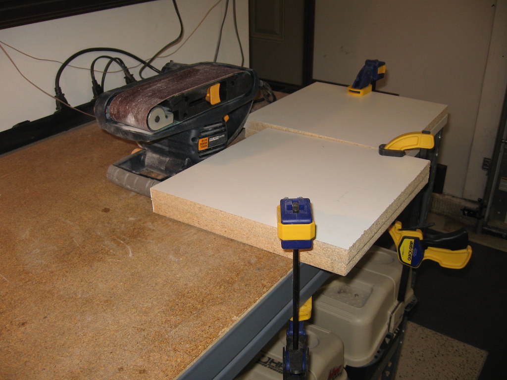
Anyway, I put together the minimal set up by just "blocking off" my belt sander so it doesn't slide around all over the table.

4237454847_9ed07675c2_b.jpg


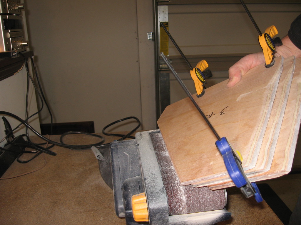
I then clamp the fins together at consistent spacing and in line with the angle I'm trying to achieve (shallow on the trailing edge, steep on the leading edge). I then rough sand down to the mid point on both sides.

4237454849_662ba9e38f_b.jpg


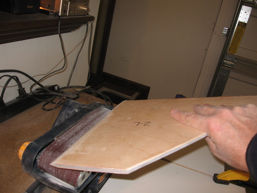
I then unclamp and "fine sand" each individual fin to get the smooth curvature I want (definitely art, not science here).

4237454855_b15ef2bf7b_b.jpg


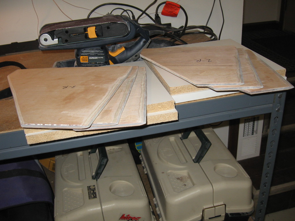
After working steadily with my available time over the last two days FINALLY all six are done!

4237454861_8baf0a5677_b.jpg
 
Now on to the critical booster dry fit. The motor mount tacked together with 3M 471 clear tape (great for masking paint jobs also).

4240229555_98bb862ce1_b.jpg


Then after a slight bit of sanding/trimming the fin slots making sure all six fins (one pair at a time) and associated butting CR's match all the Rocksim dimensions--from fore end.

4240229559_87047f03a5_b.jpg


Then from the aft end.

4240229567_39f9f50ebe_b.jpg


Soon will be coming together "permanently."
 
CA won't really help with metals & wood.
Your best bet would be some JB Weld type of epoxy.
I've stopped using T-nuts a while back. They always want to pop out over time.
Threaded insert work very well for this application.


JD


I've used the inserts for motor retention with clips as well. I wicked CA into the outer threads to hold them, but even with CA they worked loose. That was before I purchased a kit with T-nuts for retention. I've been using them for years and have only this past year started to use the Aeropak retainers. I have an Aeropak tail cone retainer for my ARCAS rocket I'm building. I think I will be using Aeropak and Slimline retainers from here on out.
 
Hmmm... My experience has been completely the opposite. The T-nuts (the ones with the little grip teeth) when backed by a layer of fiberglass never come loose. Whereas the threaded inserts installed with epoxy (whether JB Weld or other) just don't hold. I only use the second method if I'm forced to during a retrofit.

CA won't really help with metals & wood.
Your best bet would be some JB Weld type of epoxy.
I've stopped using T-nuts a while back. They always want to pop out over time.
Threaded insert work very well for this application.


JD
 
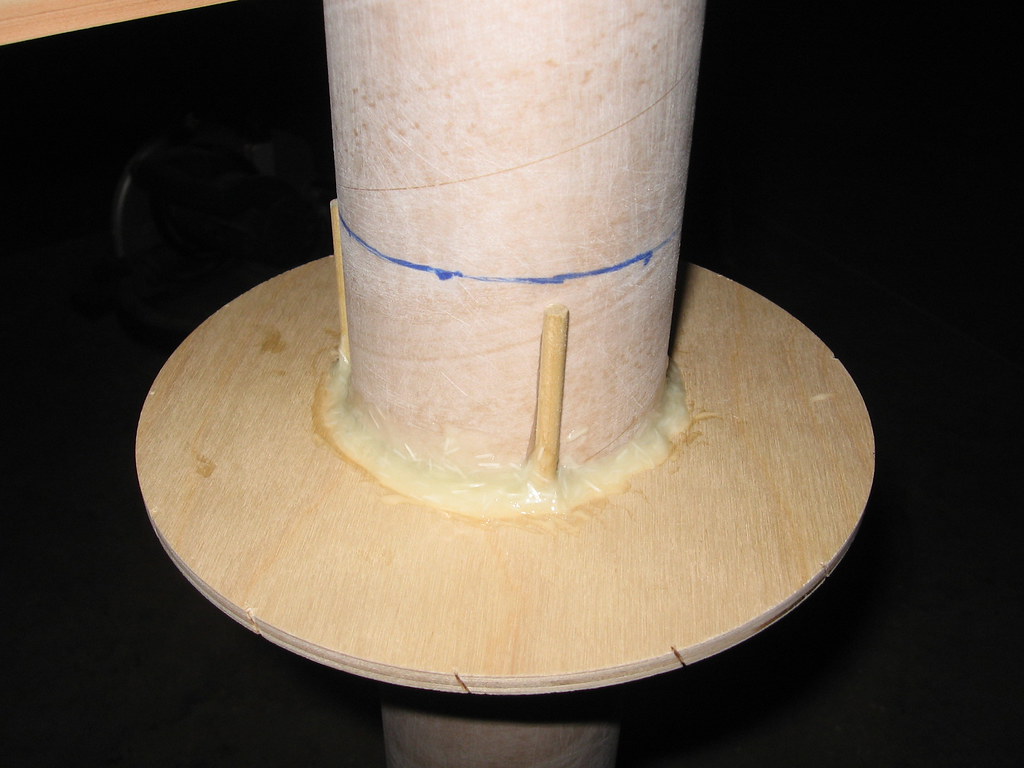
O.K. just embarking on the structural build with the CR's on the MMT. In building the split-fin fin can assembly sequencing is critical. I work from the outside in using a sequence developed for other split fin rockets (Binder Raptor, Rocketman Praying Mantis, etc.). Before epoxying the middle centering ring, I have found it very beneficial to attach "positive stops" for the "next in sequence" CR. This is an assurance that when you push the second CR down into the middle area of the rocket (on the far end of the fin slots), it will perfectly align with the fin slot openings and also be perpendicular to the MMT all around. Here they are applied with 5-minute epoxy (I'm using three 3/16" dowels, but most anything will work in this application).

4247048615_11e5e6182a_b.jpg


And here's the first (middle of five) CR in place using T-88 and a healthy dose of milled fiber and 1/4" chopped strand.

4247048617_7862a6cab8_b.jpg
 
Last edited:
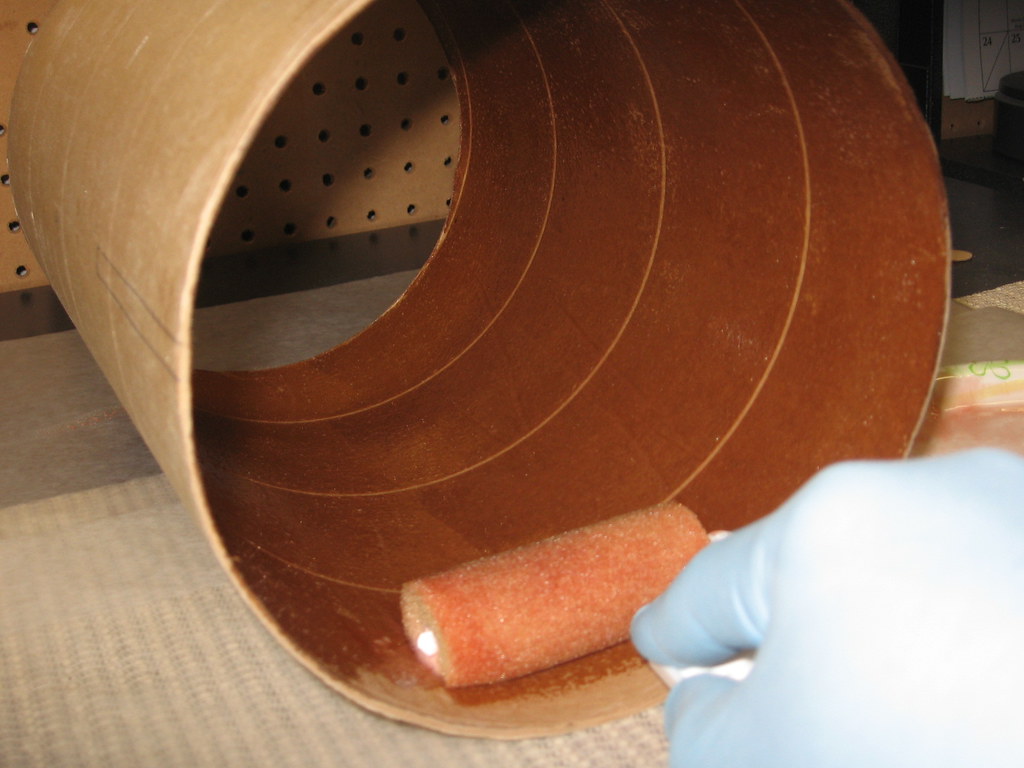
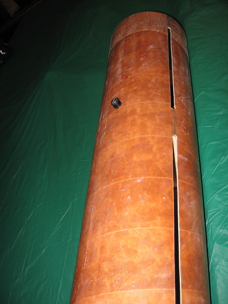
While drying I move over to the tube coupler at the top of the booster. First I mark for insertion and outline the fin slot cut outs. Then I begin applying epoxy for a layer of 6 oz. fiberglass reinforcement.

4247048621_39518c31cd_b.jpg


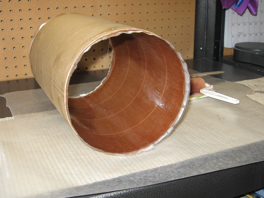
Application of fiberglass complete. If you look on the left side you can see the fin slot outline to be cut out after the epoxy dries.

4247048625_55477c71f6_b.jpg
 
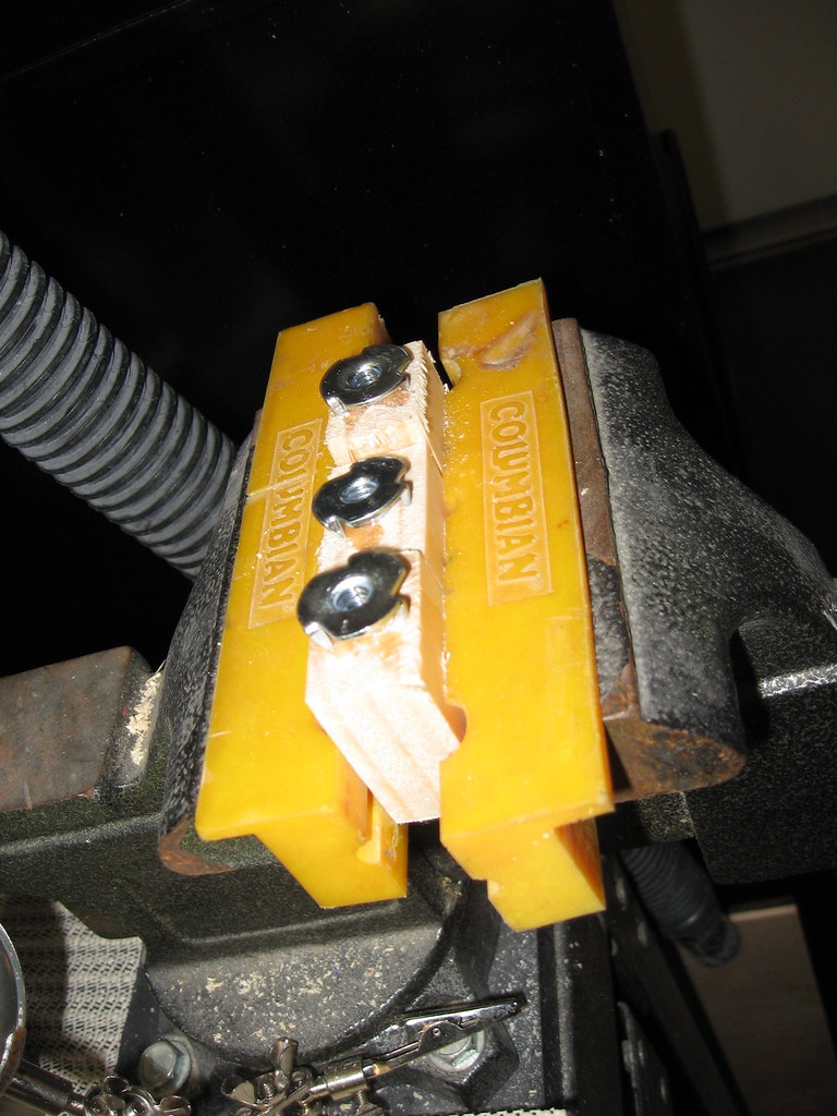
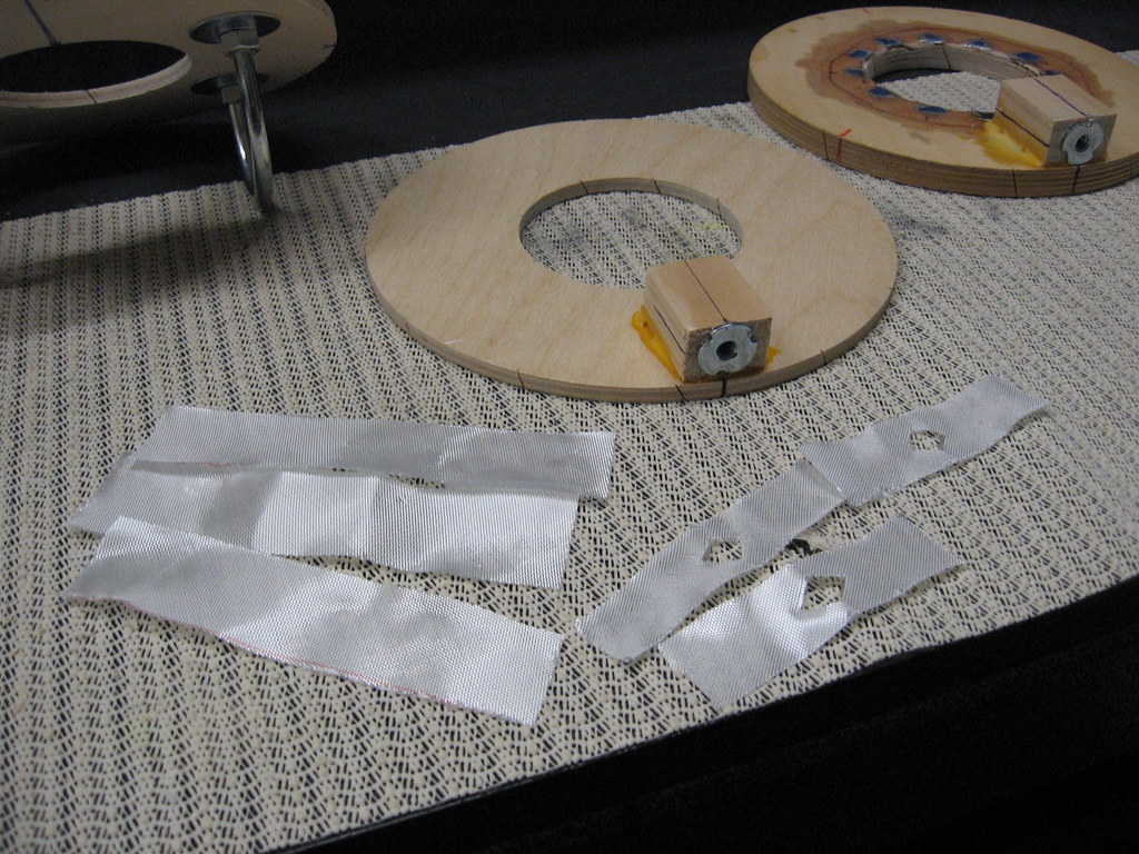
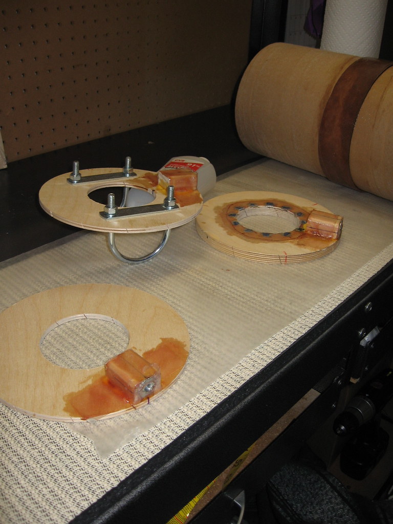
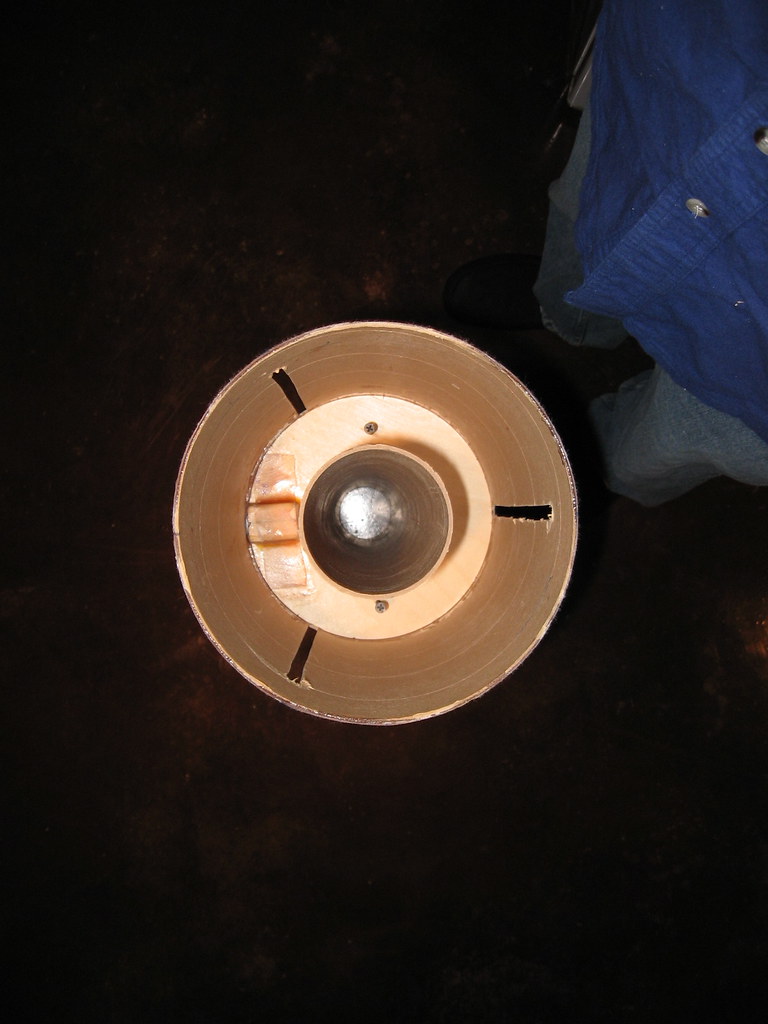
Before I install any more centering rings I have to prep for the rail button attachment. Blocks cut and T-nuts ready to insert.

4251465851_451a86d801_b.jpg


Used wood glue to attach the aligned blocks. But since these things will never again see the "light of day" after the CRs are installed, I don't want them popping loose so I wrap with fiberglass cloth (yeah, I know, overkill, but it's just the former reliability engineer in me--no hidden failures).

4251467709_0b9e86e476_b.jpg


Wet out and curing. I had some epoxy left over so I went ahead and installed the avionics bay BT section (back right).

4252243726_5591837f74_b.jpg
 
Last edited:
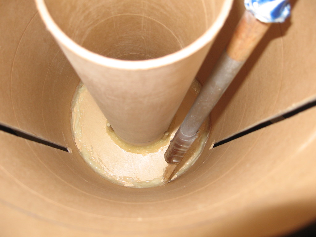
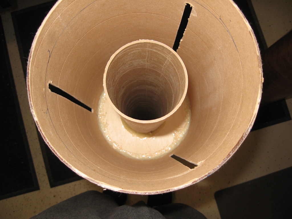
Time for the motor mount and airframe to come together. Spreading the epoxy mix (looking inside from the aft end the application is between the split fins).

4253911618_b3563f531d_b.jpg


MMT now inched up into measured position with fillets spread nicely. Now just add one aft centering ring (one on each end to hold all aligned) and then put aside to cure.

4253911620_45506b3f8a_b.jpg
 
Last edited:
Nothing too exciting here... Second CR installed at fore end of aft fin slots. The 3" drywall screws in the picture were used to ease the CR in and out and do a bit of adjustment/alignment--they come out before the fins are installed.

4254094221_8d2b5f6a1d_b.jpg


Oh, I guess one thing not too exciting, but important--the mid-CR fits "just right."

4254094241_7e2563f221_b.jpg
 
Did you flip the aft fin around 180 just to see what it would like?
Is it okay if I borrow your railbutton countersunk flathead screw method?
Nice job preempting any criticism of overkill on railbutton mounting, but
you really already had us covered with ground rule #2.
 
mIcahel,

No, during the dry fit picture the fins are installed correctly. But I kinda see what you mean, from the angle in the second picture, and I believe a bit of "fish eye" distortion from the lens, the angles look wacky. The first picture taken from the side shows shows the shapes much better (and I didn't touch the fins between shots).

But, actually, if your suggesting I turn them around just to see--I should--I'd be pretty close to having an 8" Thor.

Railbutton countersinking, heck, steal whatever you want.

Oh, don't worry, certainly heard the "overbuild comments"--I'm O.K. with that, I'll just join OA (Overbuilders Anonymous) after I get my L3 done. ;)

-Tim

Did you flip the aft fin around 180 just to see what it would like?
Is it okay if I borrow your railbutton countersunk flathead screw method?
Nice job preempting any criticism of overkill on railbutton mounting, but
you really already had us covered with ground rule #2.
 
Last edited:
Well, if you've been following the build, clearly the next step is fin attachment. But before I do that, I feel obligated to circle back and address some PM's and emails I have received regarding the fin design.

Before that though, a general comment... And I don't want to start a "firestorm" here, but without pointing any fingers, I have found over my 10 years in this hobby, that many of us will make a statement and represent it as fact, but then when pressed, cannot back it up. Of course, it's actually O.K. if someone says "Hey, this is my strong opinion, but its only an opinion...", i.e., not fact based. Or it could be well qualified with "it is my experience" and then provide a qualitative description as an example--but a single, or a most two or three examples is not a truism.

In any case, this is what I have run into when folks are quick to criticize a design choice or build path. They'll quickly point out what they think is wrong and why their way is right, but then when asked "Why?", or, "Please explain/show me?" they either can't or don't have the means to do so.

I try not to be that type of person. Maybe its the early engineering training and the years of leading teams that built some of the largest and most widely-deployed, 6-nine's availability communications equipment in the world? I don't know? But I do know that one thing I love about this hobby is that it allows me to both de-stress by working with my hands, and at the same time, exercise my mind in technical realms that I'm not trained in. Thus, when I make a design or build choice, its not due to a whim, or "because it's always been done that way," but because I think it through and prove it to myself.

And, as has been mentioned, compared to most, I do overbuild. But I don't do it blindly, there is a method to my madness. Case in point are the fins in this design. I decided to pursue a laminate for a number of reasons--some practical, some self-imposed challenges. Some say its "overkill", some say its "plain wrong." On the other hand, I felt it was one right choice (I'm sure there are others) given my design goals and constraints.

So anyway, as a result of all this, I have stepped back and taken a deeper look at this subject (i.e., application of laminates to HPR fin design) and how it specifically relates to my L3 rocket including an analysis of options suggested by other experienced rocketeers. A big caveat is that my examination is as a hobby participant seeking truth by assembling and applying information--I'm certainly not an expert in the field. I also know I'm probably exposing myself to more criticism by sharing this, but that's O.K. especially if I can turn it into a learning experience. So if you are interested, I have posted this "Appendix" to my design document entitled "Commentary on Flutter and Fin Design" at: www.tinyurl.com/Flutter2.
 
Last edited:
There are not many HPR forum contributors who post the level of detailed
plans and construction photos as you have done here. Thanks for posting
your progress. I wouldn't waste too much time responding to the naysayers.
 
O.K., enough controversy, on to the fins!

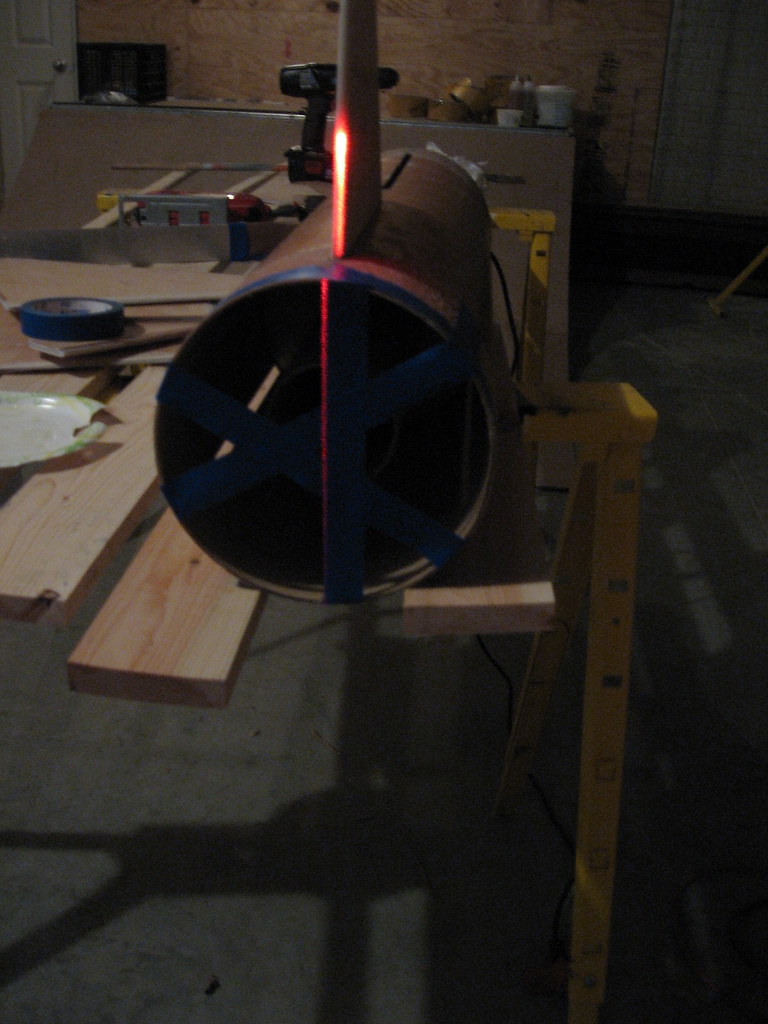
I don't know how you guys align your fins. I would be open to any new ideas as I'm notoriously bad at this. Again, I aspire to the Jim Jarvis method, but as I'm not a craftsman or an artist, I doubt if I could build such a template. So I'm using a method I first saw here. At first I was also bad at this, but then realized I needed multiple measures and required the right angles/distances for the size of fins I was working with at any one time. In any case, here's what I do.

First I use the BSD fin template mentioned earlier and make cross BT marks to get the 180 degree mark on the opposite side of the fins. I then apply a strip of masking tape across from the fin mark to the opposing mark for each fin. If I've done it right, I see the exact center in the middle of the MMT opening.

4256656326_d1f37b8f6c_b.jpg


Then I set up a laser level (well it's the opposite of a level--used by mounting on a tripod to get a vertical line). For big rockets I like to be 15 feet back or so, for smaller rockets, closer. I then measure equal distances from a reference point (in this case a wall) to the center of the fin and the laser source and also make sure my BT is parallel to the reference wall.

4256656328_9d3709255a_b.jpg


I then aim and align the laser along the edge of the masking tape up into the fin body. I still only tack these on with 5 minute epoxy just in case I make a mistake and need an adjustment on a fin. But in general, this method works pretty darn well (sorry about this last pic--I had to turn the flash off to get the laser to show up, and thus its pretty blurry--but I think you get the idea).

4256656330_efbf49463b_b.jpg
 
Last edited:
I like the laser level method you are using, especially if you already have a laser level. I'm not sure I would run out and buy one just for aligning fins on my rockets.

I think this method would much easier on rockets with 4 fins as the opposite fin is the alignment target, but your method for finding the opposite alignment target on the airframe works well.
 
dixontj93060,

You mentioned how others may do their fin alignment.

Have you considered using a machinist's combination square with a centering head, and level and or angle finder?
https://en.wikipedia.org/wiki/Combination_square

When I was a pipefitter I used the machinist square a lot.

The center head attachment slides along the machinist rule and can be tightened down.

You place the airframe tube in a somewhat level position and can clamp it or secure it to start.

Take the machinist combination square (12" rule, 90 degree attachment, and the center head) and loosen the centered so that it will slide on the rule.

Hold the rule vertically about top dead center on the airframe.

Bring the centered down to the airframe so each side touching is flat on the tube. The rule should be just touching the tube as well.
Tighten the center head.

Now you have a tool that when placed anywhere on the airframe will touch it at a point that will be perpendicular to the outside (O.D.) and the rule will point to the center of the airframe. In effect the rule becomes a segment of the "ray" that goes out from the counterpoint to infinity.

To find the actual top dead center of the tube put a level on the square attachment and roll the combination until level. You can use a torpedo level or pendulum type angle finder.

Once level, at the point where the rule touches the airframe make a tic mark. This is top-dead-center. The base reference point for all other points on the 360 degree tube.

If you are just starting the marking process for fins you can make the 0-degree where the first fin center goes, roll the combination to the side so that you are now 90 degrees out and mark, you now have the center of the second fin (if 4 fins).

For 3 fin placement instead of 90 edges you would go 120 from the 0-degree mark. See where I'm going here?

When attaching any fin you can roll the tube assembly so that that fin's reference mark is top dead center. Use your method to attach the fin. placing a level on the side of the fin you can check for plumb. If the fin reference is top dead center and the fin center is on its mark, the fin becomes a "ray" from the center of the tube.

Just keep repeating the process.

I was a marine pipefitter building submarines for 20 years. This is the method used when attaching fittings to the outside of pipe tube. I have done this on everything from main steam to diesel exhaust to nuclear. It works.

I have a combination square set on my bench right now and use for eyeballing fin placement on my smaller diameter rocket airframes.

William
 
Last edited:
Sounds like a great method!

dixontj93060,

You mentioned how others may do their fin alignment.

Have you considered using a machinist's combination square with a centering head, and level and or angle finder?
https://en.wikipedia.org/wiki/Combination_square

When I was a pipefitter I used the machinist square a lot.

The center head attachment slides along the machinist rule and can be tightened down.

You place the airframe tube in a somewhat level position and can clamp it or secure it to start.

Take the machinist combination square (12" rule, 90 degree attachment, and the center head) and loosen the centered so that it will slide on the rule.

Hold the rule vertically about top dead center on the airframe.

Bring the centered down to the airframe so each side touching is flat on the tube. The rule should be just touching the tube as well.
Tighten the center head.

Now you have a tool that when placed anywhere on the airframe will touch it at a point that will be perpendicular to the outside (O.D.) and the rule will point to the center of the airframe. In effect the rule becomes a segment of the "ray" that goes out from the counterpoint to infinity.

To find the actual top dead center of the tube put a level on the square attachment and roll the combination until level. You can use a torpedo level or pendulum type angle finder.

Once level, at the point where the rule touches the airframe make a tic mark. This is top-dead-center. The base reference point for all other points on the 360 degree tube.

If you are just starting the marking process for fins you can make the 0-degree where the first fin center goes, roll the combination to the side so that you are now 90 degrees out and mark, you now have the center of the second fin (if 4 fins).

For 3 fin placement instead of 90 edges you would go 120 from the 0-degree mark. See where I'm going here?

When attaching any fin you can roll the tube assembly so that that fin's reference mark is top dead center. Use your method to attach the fin. placing a level on the side of the fin you can check for plumb. If the fin reference is top dead center and the fin center is on its mark, the fin becomes a "ray" from the center of the tube.

Just keep repeating the process.

I was a marine pipefitter building submarines for 20 years. This is the method used when attaching fittings to the outside of pipe tube. I have done this on everything from main steam to diesel exhaust to nuclear. It works.

I have a combination square set on my bench right now and use for eyeballing fin placement on my smaller diameter rocket airframes.

William
 
Last edited:
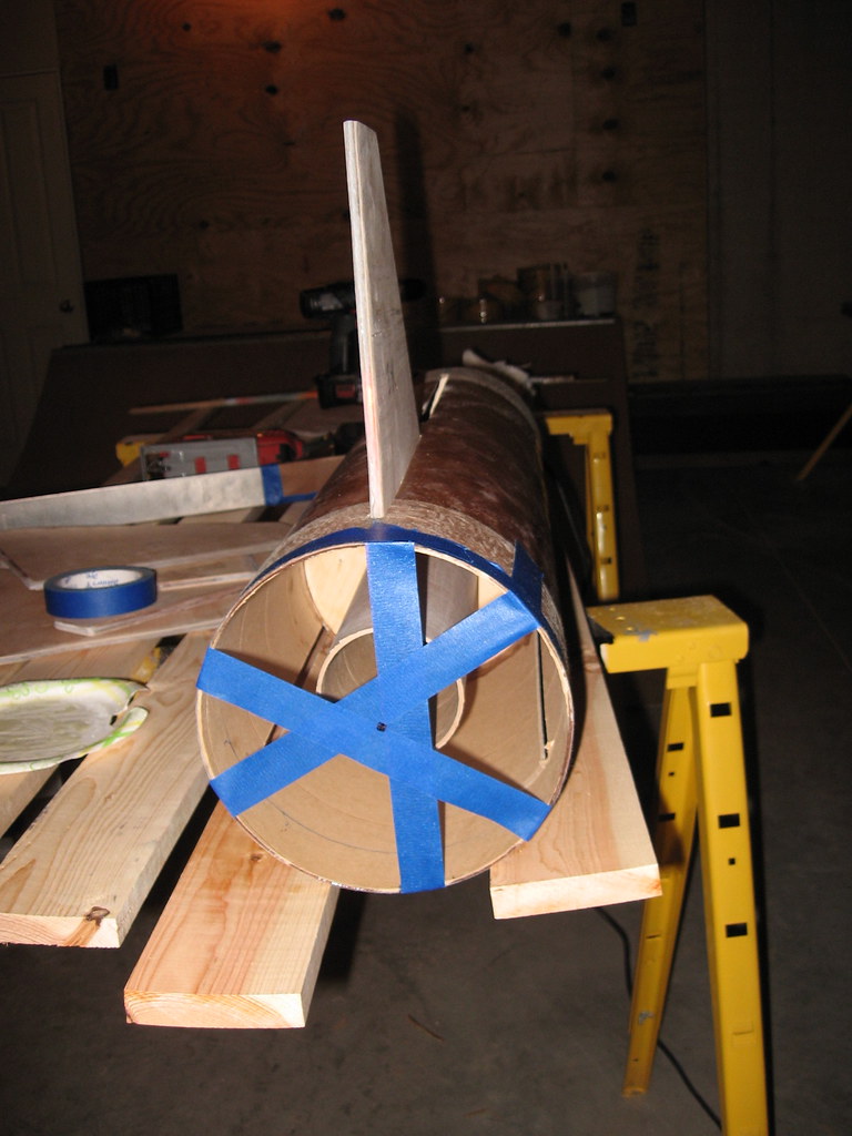
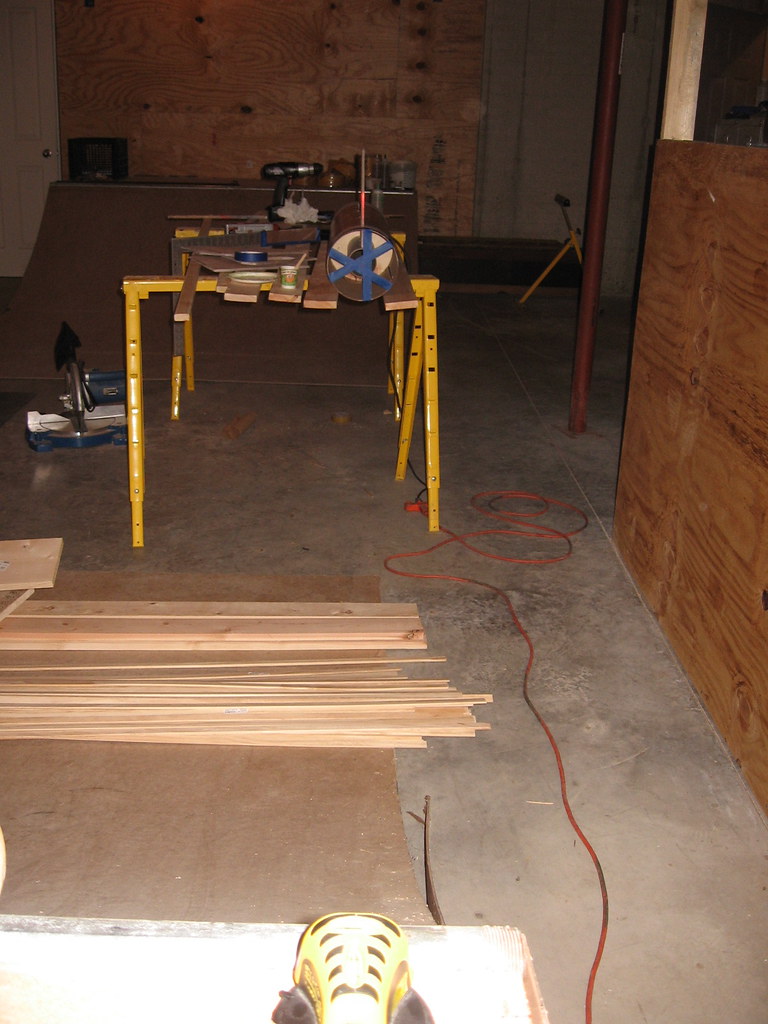
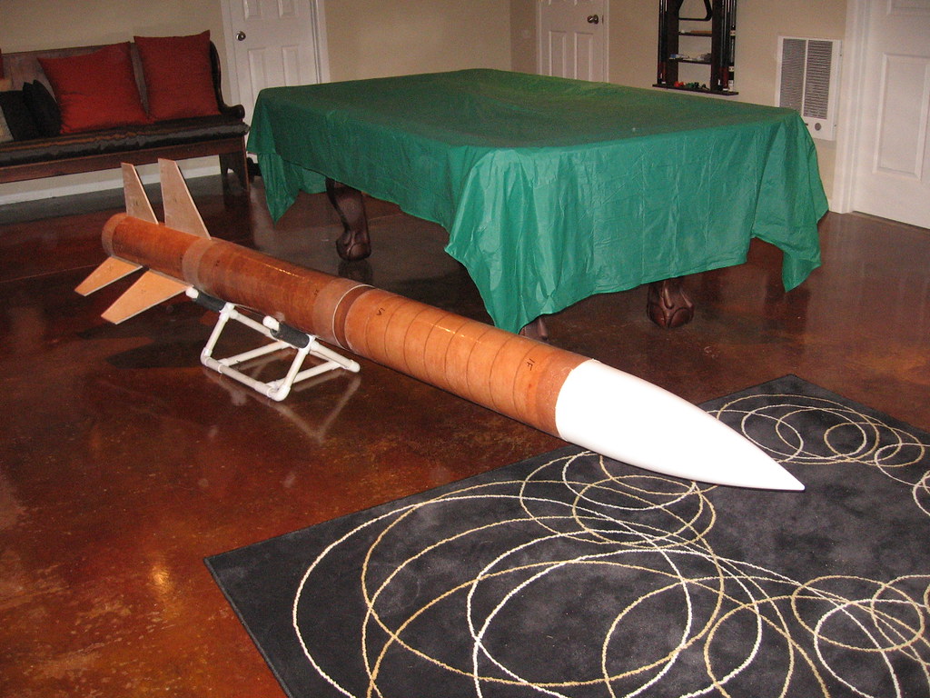
Between finishing up client work for the week and shoveling snow, I was able to get all six fins attached yesterday. I have a ton of work left (I've attached an the updated build checklist), but it's beginning to look like a rocket now (the picture was taken in my game room in front of the pool table to give you a perspective of the size).

4257733135_34465c68b1_b.jpg


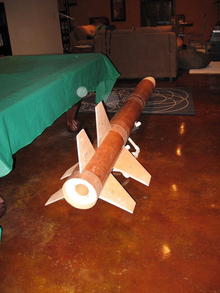
And from the aft end.

4257733147_0435608b01_b.jpg


Seems like a good "breaking point" -- it'll have to be as I'm heading out today for a business trip/conference in Florida next week (well my wife is coming along, so I'd say 50% business, 50% R&R).

View attachment Build step detail_v1_3.pdf
 
Last edited:
Having built enough rockets and seen the fins shred, I too, have a tendency to "overbuild". But, I've learned the hard way and I don't like rebuilding, so I try to make sure I have success everytime.

So I guess what I'm trying to say is take advice with a grain of salt, use what you can, but I say how you're doing looks like the best way to me. Nice build so far.
 
And from the aft end.

4257733147_0435608b01_b.jpg

Something is not right with this picture. Your build thread indicated that you would be using an Aeropak retainer of the flanged variety. Pictures even showed drilling the holes and installation of t-nuts. Heck, one picture even showed the retainer afixed to the centering ring. The rear centering ring in this picture does not look like it is set up for that Aeropak retainer.

Did something in the design change?

Seriously, very nice job.
 
Mark,

No it's the same CR. It may be misleading because I do have two longer than normal screws inserted at 3 and 9 o'clock (actually maybe more 4 and 10 o'clock in the picture--but you get the idea) only as a means to pull it in/out.

-Tim


Something is not right with this picture. Your build thread indicated that you would be using an Aeropak retainer of the flanged variety. Pictures even showed drilling the holes and installation of t-nuts. Heck, one picture even showed the retainer afixed to the centering ring. The rear centering ring in this picture does not look like it is set up for that Aeropak retainer.

Did something in the design change?

Seriously, very nice job.
 
Last edited:
I've done the same when dry fitting the aft most ring.

I drilled through holes for the temp fasteners that would line up with the fins as well so there is a place for the epoxy around the retainer to anchor.

Wm.
 
The fin configuration looks better on the rocket than it did in conceptual drawings. Good work!
 
Tim

Looking good. Maybe I missed it but what size chute you going with? What manufacturer?
Keep the pictures coming! Can hardly wait to see it go!
 
Back
Top