Thank you all for the replies. Obviously, I've substantially misunderstood what exists at the forward end of an L1000. This all helps. So, individually...
@mikec, as rfjustin has guessed, this is indeed a Wildman Mach 2 project. While the AT L1080 may be one of the motors used "along the way" I, ultimately, want to fly an L1000 in it at least once. I have a substantial investment in CTI cases / components so I'm trying to come up with a way to use them along the way too. There is actually a
second Mach 2 which a friend is hoping to build as a L1/L2 cert. In that case, he hopes to fly on a CTI 38mm for L1 cert, a hotter CTI 54mm for L2 cert, and, hopefully, an L1000 for some Mach 2+ fun once certified.
My research here is mostly so that I can suggest a solution which accommodates that whole range without excessively decreasing the space available for recovery. While the Aero Pack forward retainer, and its related adapters, extensions, etc., is an obvious solution, that whole "stack" uses up about an extra 1.5 to 2 inches out of the precious recovery space; especially when you consider it must be mounted at the farthest forward point to accommodate the longest motor (and adapter stack) that one intends to fly. I'm hoping to design / build something which offers similar utility yet doesn't take up quite as much space. I may conclude that it's just not practical to do it this way, but I'm not quite there yet... ;-)
@tfish, yes, thank you, and for the other comments / information from earlier on in the post. The links you provided give some insight into what's going on in the construction of the motor itself. Very valuable. While I'm open to solutions bordering on experimental motors, I'm hoping to avoid that in my recommendation for my friend on the L1/L2 cert path; at least initially. ;-)
@JimJarvis50, thank you for the comments and the photos. The photos help clear up some of the questions I've had on the construction of the motor itself. I wasn't quite sure how the charge well interacted with the epoxy crown / dome. And, as mikec pointed out, AT likely doesn't publish the drawings as that gives them some freedom in evolving the internal build process a bit. This is all starting to support my thoughts that I'm going to have to get a motor(s) in hand, spent or otherwise, before I can really "lock in" any design I come up with given that I'm hoping to accommodate such a large variety of motors. Again, the pictures help a bunch. Thank you.
@rfjustin, yes I like that idea too. If I was just setting up a rocket to fly one brand / model of motor, that would be perfect. And, I may end up doing that in my own rocket. I'm still holding out hope that I can come up with a "clever" solution which accommodates a wide range of motors.
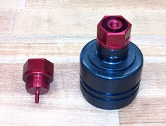
gfunk has a nice design for a MD retainer here
Wildman's MACH 2 rocket. One advantage, relative to Aero Pack's similar device, is that it doesn't get bonded in. Instead the little cylindrical array of threaded holes allows it to be moved fore and aft to accommodate a small range of motor lengths.
And, there's the classic bolt (or all thread) through a bulkhead like this
Wildman's MACH 2 rocket shared by Cameron Anderson.
Along with some combination of friction fit and/or aluminum tape, any of these solutions are likely to work. One common aspect is that I'll need to know the dimension a) from the front of the thrust ring to the absolute most forward protruding feature of the motor AND b) the front of the thrust ring to wherever a user threaded "nut" would begin and end in order to make much progress. Without being a PITA to anyone who offered dimensions, I think this is going to take some motors in hand... ;-) I'm starting to feel a little guilty that I've hijacked the thread too, though I promise to publish any information I'm able to glean.
Again, thanks to all for comments and information! It is greatly appreciated.