Critical Mass: my first scratch payload two-stage rocket

The Rocketry Forum

Help Support The Rocketry Forum:

This site may earn a commission from merchant affiliate links, including eBay, Amazon, and others.

morlock

Well-Known Member
Joined
Jun 18, 2014
Messages
630
Reaction score
4
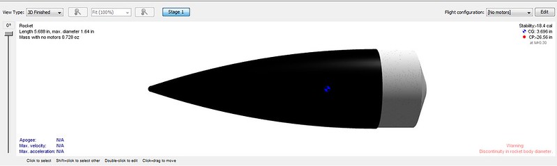
I'm in the final stages of design for my scratch payload two-stage rocket. I'm trying to apply the "Measure twice, cut once" maxim so I'm asking for your input and suggestions about the design. Below is snapshot of the Open Rocket design file. You can find the file here.

payloader.jpg

Here are two snapshots of the components and design station (ahem, kitchen table).

IMG_20140831_083838_small.jpgIMG_20140831_084734_small.jpg

Here are some questions about the design for which I would appreciate your input:

1) Does the global design look sound?

2) Do the stability values (in BT caliber) seem OK?

3) For the payload area, I plan to use kevlar chord with loops to close the forward bulkhead (see figure below). The goal is to have a minimal weight system. The kevlar cables with loops are used with an S-biner to keep the top of the bay from opening. The nose cone is also attached to the S-biner so, in case it pops out, everything is still attached. Do you see any potential problem with this approach?

payload_bay_design.png

4) Is it standard to friction fit motors in two-stage rockets? Are there other approaches using motor hooks? For example, I have motor hooks for which the hook part is very thin (less than a millimetre). Could I put it between the two motors without problem?

5) I saw recommendations to use cellophane tape (not masking tape) to tape the two motors together. Is Scotch Tape a sort of cellophane tape?

6) How would you use motors with a length of 70 mm in the motor tubes made for 95 mm? I was thinking of using some sort of removable motor block to fill the exceeding 25 mm.

Thanks for your input, I hope to start the build real soon!
 

Attachments

  • scratch_payloader_002_two_stage.ork
    92.4 KB · Views: 58
Last edited:
Looks like a great design.
2. 1.66 is definitely stable.
3. Looks like a good system, although I would consider a single wrap of masking tape around the nose and top of the body tube (or two small pieces of tape). If you have a sealed payload bay that should definitely hold the nose.
4. Yes, it's definitely standard. However, you might want to try gap staging instead. Especially with blocks, it really might work. Here's a quick apogee article (scroll to gap staging although the whole thing is great information): https://www.apogeerockets.com/Tech/How_2-Stage_Rockets_Work
5. If you tape the motors together, Scotch tape is the normal tape for this.
6. If you gap stage the motors (see apogee article), you can wither use spaces like you said (estes makes D to E spacers) or shorten the body tubes. If you don't want to try to gap stage, you probably will have to redesign a bit of the booster mount because motors taped together usually doesn't work well.
If you wanted to try using spacers and taping the motors:
[motor][spacer][Motor]
could work if you taped all 3.

Good luck on the build!
Thank you for the answers and the Apogee resource. It made me realize I was missing a motor stop at the bottom of my booster stage.

I'll consider gap staging solutions using a spacer (maybe an expended 24 mm motor case) if I want to use 70 mm motors.

Regarding question 3, the payload bay will not be sealed, except by my kevlar chord system.
 
Sounds good regarding the payload bay. I know you are planning to fly electronics, what will the payload for this be?

Also, for gap staging, you can actually have a lot of space between the two 24mm tubes. Apogee has a kit called the Rip-Roar that has something like 8 inches between the motors in a 54mm airframe with D motors.

Good call on the rear engine block. I've flown (and lost) and seen a lot of estes Mongooses fly and they always stage reliably in part thanks to the engine block.
I'm teaming with a friend who is doing a doctorate in Electrical and Software Engineering. The first module that he will build will have an accelerometer/gyro/magnetometer (all in one sensor unit) plus a barometer. This will be mounted on a microcontroler that he chose and, with batteries and a board, we estimated that it should weight in at approximately 30 grams. My design can accommodate up to 60 grams easily so we should be fine.

The next steps should see a GPS and radio module to send back the data in real time added. My guess is that this same rocket should be sufficient, but I may end up building another one using 29 mm motors to send the whole thing higher on F and G motors. If this happens, however, it would definitely be in 2015.

I'm really tempted to include a motor hook for the top stage and go with gap staging. I'd like the top stage to be flyable alone and I really prefer a hook to friction fit. I used friction fit only once and it worked but I like to have more safety margin and friction fit seem to take more getting used to. Since I'm new to the game, a hook seems safer.
 
Last edited:
Sounds really cool! For GPS, if you do decide to go with composite F and G motors, be aware you cannot stage them without electronics (you need an igniter running the full length of the propellent and lit electronically, since composite motors are usually not endburners). It's probably not a problem though, as you could fly 60 grams to 400-500 meters with a Estes Partizon or Argent, or any number of other single stage aerotech, Loc, or madcow kits.

I agree about gap staging and engine hooks. I haven't flown a gap staged rocket yet (very soon) but it seems like it should work great and make it easier to also fly the rocket single stage. When you consider that 24mm motors have stronger ejection charges than 18mm motors, I definitely agree about the extra safety margin.
I plan to stay with composite motors for two stages or to do a single stage with F/G. If I am not mistaken, some E motors have 30% more total impulse while still being composite.

I'm definitely going with a motor hook on top stage and gapped. The gap will be small though.

Here is a picture of the first version of the electronic payload. My friend just sent it to me.

IMG_20140831_140119.jpg

Getting real!
 
I'm fairly sure all estes motors (aside from the estes motors made by AT) are black powder. There are composite E's, an E9-6 only has 27.5Ns (less than 50% of maximum E impulse) while aerotech 24mm E's go all the way to nearly the E limit at 39.9ns- in a smaller casing surprisingly. Do you mean staying with black powder (estes D's) for two stage?

Note: Estes does make black powder 29mm motors, but they are fairly low thrust and impulse they are what you see in the PSII E2X models that can use boosters.

Edit: forgot to mention, the electronics payload looks great! What's the power source for it?
 
Last edited:
If you are planning on using composite motors for staging, you cannot stage them like Estes BP motors stage. You must have electronics to control the ignition of the upper motor. That is more weight in addition to the payload.

I'm wondering why you are doing a two stage for testing a payload. Two stages is more risky then a single stage. If the upper stage doesn't ignite, or ignites late when it's tilted off at a low angle, you'll have a lawndart or lost rocket. If you purpose is test a payload at a certain minimum altitude, I would suggest designing a single stage that will lift your maximum weight to that minimum altitude on a mid to upper range motor in the designed diameter. That way you can use smaller motors for lighter or lower flights and the largest motors for heavier or higher flights without the additional risk to the payload that multi-stage rockets pose.
I guess I mixed composite and black powder. I thought they referred to the same thing. I meant Estes black powder.

I'm doing a two stage for the challenge of it. I also make sure my design is flyable as a single stage and will certainly start testing it as a single stage, without even the real payload in. I'll then go single stage with the payload. If everything works well, I'll then try with the booster but dead weight instead of the payload, and only then with the actual payload in.

The bottom line is, I wanted to do a scratch build that would challenge my design and building skills. That's why I went for this kind of design.

Thanks for your input!
 
Sounds like a great plan, and should be fairly safe. Just do a few staging tests before flying the payload 2 stage. If you haven't flow a two stage rocket before, it's definitely an awesome part of rocketry. You could probably also adapt this to be a very nice egglofter for competitions, with a different nose/payload bay.
Just to clarify regarding engines:
Composite- All Aerotech and CTI, Loki, etc. Plastic or metal casing, the igniter runs the full length of the propellent.
Black powder-Estes or quest (including the Estes 29mm motors with paper casing, which stage like all black powder), paper casing, ceramic nozzle.
 
If your payload includes a baro sensor, do not to forget a vent hole in your payload bay. Otherwise your payload might have a problem seeing the change in air pressure. Many vendors of Baro Altimiters have a guide to how to vent based on the size of the payload bay/altbay.

Also, if you might ever think about considering staging composites, it's simple to add a duct for the wiring now, and a real pain to retrofit.
I have an estes altimeter and the plan tells how big and how many the vent holes should be. I'll be using this as a guide. What I am a bit more clueless about is how big the vent holes between the booster and the second stage should be. I'll need them since my design is now a gap staging rocket. I plan to make 4 holes.

I am not thinking about staging composites for now. I'll see there and then if it ever happens! :)

Otherwise, here are the modified plans. And another screenshot:

critical_mass_screenshot.jpg
 

Attachments

  • scratch_payloader_002_two_stage.ork
    149.9 KB · Views: 62
I have an estes altimeter and the plan tells how big and how many the vent holes should be. I'll be using this as a guide. What I am a bit more clueless about is how big the vent holes between the booster and the second stage should be. I'll need them since my design is now a gap staging rocket. I plan to make 4 holes.

I am not thinking about staging composites for now. I'll see there and then if it ever happens! :)

Otherwise, here are the modified plans. And another screenshot:

View attachment 183014

As far as inter staging vents I've never uses on on BP birds, You want the first stage to pop ASAP so it doesn't get toasted by the second stage motor.
 
As far as inter staging vents I've never uses on on BP birds, You want the first stage to pop ASAP so it doesn't get toasted by the second stage motor.

You're right, but the problem is when you have long gaps like 4 - 8 inches or longer. You have to have vents up near the sustainer so the air in the motor tube has some where to get out of the way of the hot gases, and burning particles so they can igniter that upper motor before the two sections separate. If you don't have the vents, the pressure in the motor tube separates the two sections before the burning propellant can reach the upper motor and you don't get sustainer ignition.
 
You're right, but the problem is when you have long gaps like 4 - 8 inches or longer. You have to have vents up near the sustainer so the air in the motor tube has some where to get out of the way of the hot gases, and burning particles so they can igniter that upper motor before the two sections separate. If you don't have the vents, the pressure in the motor tube separates the two sections before the burning propellant can reach the upper motor and you don't get sustainer ignition.
So, what about if the gap is about 1/4 of an inch, like in my design? Should I add vents? My inclination is to do it. Even with an 0.25 inch gap, the gas has an easy escape route to pressurize the inter-stage volume and potentially separate the two stages.

Anyway, is there a downside to having the gaps? I'll do them through the strong tube coupler so there shouldn't be any reduction in strength compared to the rest of the tube.
 
As far as inter staging vents I've never uses on on BP birds, You want the first stage to pop ASAP so it doesn't get toasted by the second stage motor.

Then you never built one of Semroc's Omega clone of the Estes Omega Payloader. In a conversation with the late Carl McLawhorn I asked him about this, and he told me that he modified the Optima clone because too many people were having the boosters pop off without the sustainer igniting. By allowing the gasses trapped between the two engines to escape, the space wouldn't pressurize until the sustainer ignited. I've never heard of anyone having a booster toasted because of the interstaging. If one were to get toasted then that would be clear evidence that there was clearly too much friction in the friction fit of the two stages, or the sustainer had some kind of malfunction (chuffing comes to mind).
 
Last edited:
Then you never built one of Semroc's Omega clone of the Estes Omega Payloader. In a conversation with the late Carl McLawhorn I asked him about this, and he told me that he modified the Optima clone because too many people were having the boosters pop off without the sustainer igniting. By allowing the gasses trapped between the two engines to escape, the space wouldn't pressurize until the sustainer ignited. I've never heard of anyone having a booster toasted because of the interstaging. If one were to get toasted then that would be clear evidence that there was clearly too much friction in the friction fit of the two stages, or the sustainer had some kind of malfunction (chuffing comes to mind).
Thanks for the link to the assembly manual of the Omega. It helped me get a better idea how I am going to assemble the motor mounts.
 
Thanks for the link to the assembly manual of the Omega. It helped me get a better idea how I am going to assemble the motor mounts.

Glad to help... Even more glad it was still there (I've archived the .pdf, so if it ever does go down, I'll have both the digital copy, and my paper copy from the kit).

You *MIGHT* still be able to buy the Omega's centering rings from Semroc if they still have them in stock. Mind you, this is for a BT-60 based rocket.

I've now downloaded the .ork file you posted... Is that a PNC-60A nosecone?

11702790683_b713426977_c.jpg


I've got a more accurate profile in my nosecone library for it if you want to update your file some.

You might also want to check your fins/centering rings thickness/materials, as they look to be OR's default.

All the Best!
Jim
 
Last edited:
So, what about if the gap is about 1/4 of an inch, like in my design? Should I add vents? My inclination is to do it. Even with an 0.25 inch gap, the gas has an easy escape route to pressurize the inter-stage volume and potentially separate the two stages.

Anyway, is there a downside to having the gaps? I'll do them through the strong tube coupler so there shouldn't be any reduction in strength compared to the rest of the tube.

What I've done on most of my booster stages is, instead of using centering rings, I use four equally thick pieces of balsa to center the MMT in the BT. This leaves plenty of vent area between the wood strips to vent any gases from between the booster and the sustainer. I do extend the booster MMT to within about 1/4" to 1/2" of the bottom of the sustainer motor.

One caution, I don't think you have to worry about it with this design, but if you have a long gap between booster and sustainer (4+ inches) and a corresponding long BT between the booster and sustainer fins, the booster can go stable on you on the way down and core sample. The larger fins on the booster not only help with stability on the up part, but instability when the booster falls. That just become more important with longer gaps.
 
Glad to help... Even more glad it was still there (I've archived the .pdf, so if it ever does go down, I'll have both the digital copy, and my paper copy from the kit).

You *MIGHT* still be able to buy the Omega's centering rings from Semroc if they still have them in stock. Mind you, this is for a BT-60 based rocket.

I've now downloaded the .ork file you posted... Is that a PNC-60A nosecone?

11702790683_b713426977_c.jpg


I've got a more accurate profile in my nosecone library for it if you want to update your file some.

You might also want to check your fins/centering rings thickness/materials, as they look to be OR's default.

All the Best!
Jim

The cone I use is from a Patriot kit. Are the omega centering rings interesting because they are vented? If yes, I could easily make something similar by myself, as Handeman has suggested.

If I vent the booster centering rings enough, do you think that I still need to drill holes in the BT?

I did not understand the reason for the big booster fins since smaller ones were enough to guarantee a stable flight. I didn't think of their role in the tumbling descent of the booster.
 
Last edited:
Thanks to your help, I thinks I got 99% of the design ready. I am still not sure where to put the launch lugs though. I am thinking of putting two of them, both on the second stage, one at the fin level and the other one just above the centre of gravity since I may launch it with more than the 34 grams of payload included in the design. I want to be able to safely launch either only the second stage or both stages together.

Does that sound good? Should I add a third lug to the booster stage?
 
The cone I use is from a Patriot kit. Are the omega centering rings interesting because they are vented? If yes, I could easily make something similar by myself, as Handeman has suggested.

If I vent the booster centering rings enough, do you think that I still need to drill holes in the BT?

I did not understand the reason for the big booster fins since smaller ones were enough to guarantee a stable flight. I didn't think of their role in the tumbling descent of the booster.

Can you give me a part number on the NC, or a kit number for the Patriot? I'd like to see what NC it uses.

Yes, the Semroc Omega's booster CRs are vented, and designed for a 4 finned TTW rocket. I asked Carl if he could produce vented CR's for a 3 finned TTW design, but he didn't get a chance to before he passed.

No, you won't have to drill holes in the BT for venting the staging event. I haven't studied your rocket in too much detail, so you still may need vents for electronics, but not for staging.

Two LL's are advised. A 3rd one would just be additional work/weight/drag. I don't know of anyone who has a LL on a booster, and I'd advise against it, unless you intend to be able to fly it separately as a rocket of its own.
 
Last edited:
The build is started, and I even found a name for the rocket. It is designed to carry a payload of a minimal weight or mass and to split in two, which made me think of nuclear fission. Thus: Critical Mass.

For now, I have cut the tubes and the fins, have assembled both motor mounts with only the first centering ring (I'll fix the other one once the fins have been fully prepared) and build the payload bay. Here are some pictures of the components and early stages of the assembly.

02_components_small.jpg 07_cut_tubes_small.jpg 08_cut_fins_small.jpg
09_motor_mount_small.jpg 10_payload_bay_small.jpg 11_payload_bay_and_motor_tubes_small.jpg

And the payload:

03_payload_001_small.jpg
 
This thread has been dead since a few months but I didn't add an update about the flights I did with this model, which in the end I named the "Fission".

The Fission flew 4 times. The first two times only with the second stage, on D12 and E12. All went very well with altitudes slightly above 200 and 400 meters. On the second flight, I lost it in a low hanging cloud. I had no idea clouds could be that low... I had to run after it as wind carried it away but was very lucky that it landed in a small clearing.

The third flight used both stages with the booster carrying a D12-0 and the second stage an D12-4. The flight was beautiful with a clean separation and slow tumble of the booster. I was encouraged so I loaded an E12-0 in the booster and an E9-6 in the second stage. This added something like 40 grams compared to the previous flight, which made the liftoff significantly slower. That was my mistake. The person responsible for pressing the fire button didn't seem to care about my recommendation to wait between wind gusts and the weathercocking was pretty extreme.

With 2 seconds of thrust on the booster, the rocket was already far from vertical. The 3 seconds of thrust of the second stage brought the rocket to about 45 degrees. I already felt like that rocket was lost. Then the 6 long seconds before the ejection charge were enough to have the rocket ~500m away over the closest fields. The wind finished the job as the rocket drifted into a corn field.

I searched for 45 minutes with my girlfriend be we could not locate the Fission. I was a bit deflated. In fact, I haven't done anything rocket related since then until about last week.

I think I'm hearing the call again loud and clear though. Maybe I'll even rebuild that second stage to use with the booster, the only part we did locate :)
 
Sorry to hear about the loss of the rocket. It looked like a well planned project and the the bit of workmanship you pictured was stunning---very nice. One thing about two stage rockets, sooner or later they find their way to the county next door. Rebuild it and get some pics out of the finished product. ---H
 
Sucks when you lose a rocket. Any chance you could go and check again, or has the weather been such that it'd be a write off?

I'd advocate for a beeper (even a dollar store "door alarm") and a very bright LED to be installed with it.
 
Sucks when you lose a rocket. Any chance you could go and check again, or has the weather been such that it'd be a write off?

I'd advocate for a beeper (even a dollar store "door alarm") and a very bright LED to be installed with it.
The rocket landed in a corn field just prior to harvest... I guess the chances of finding that second stage is pretty null.

As for the beeper, I felt dumb on that day for not having one installed in this rocket. I am looking for a very lightweight option since my rockets go up on E motors at the most for now. The Canadian store where I buy my supply has one but it weights 19g. That's a bit high for rockets that weight from 60 to 250 grams.

Do you know of a cheap/small/low cost option? I ordered two cheap personal alarms from china but I don't know if I will be able to convert them into good beepers.
 
Back
Top