4" Astrobee 1500

The Rocketry Forum

Help Support The Rocketry Forum:

This site may earn a commission from merchant affiliate links, including eBay, Amazon, and others.

TheAviator

Well-Known Member
Joined
Jan 18, 2009
Messages
935
Reaction score
122
A quick post on this model tonight and more at a later date.

Over the past month and a half, my brother and I worked on our NARAM-56 scale model. Working on my successful if somewhat rushed BT70 model from N55, we chose a 4" LOC tube based model for Giant Sport Scale at N56. The 4" main airframe worked out to using 29mm MMT coupler, 29mm MMT, and BT-55 coupler for the Recruit motors to within 2% of scale. These three tube sizes actually nest perfectly; the only disadvantage is that they are somewhat heavy overall.

The center motor mount is interchangeable. We built a 38mm, 29mm, and 4x24mm mount for the bird and ended up using the 29mm. The fins bolt on through a 1/8" plywood mount built into the lower airframe; the interchangeable MMTs also bolt to this structure. This makes painting the difficult roll pattern much easier, as you don't need to mask fins. The fins are either solid black (1) or solid white (3), so no masking there.

The only problem with this model is weight. We ended up stripping unnecessary parts from the model to bring it down under the 1500g limit. Two recovery U-bolts, a deployment bag and drogue, the (unused) altimeter sled, and (initially) the two CTI 24mm motors in the recruits were stripped to bring the model from ~1.9kg to ~1.48kg. Successful flights were made, one with a 29mm 3G G54 and one with two 24mm 1G E22s and a 29mm 1G F29. The second flight was made only after Tom Ha graciously allowed us to borrow a 29mm 1G case and sold me the reload.

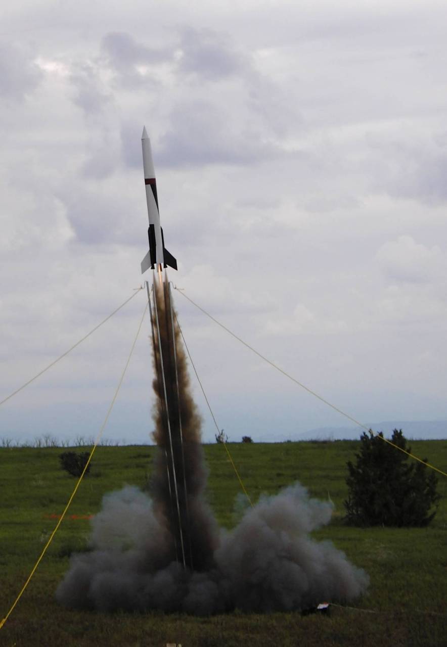
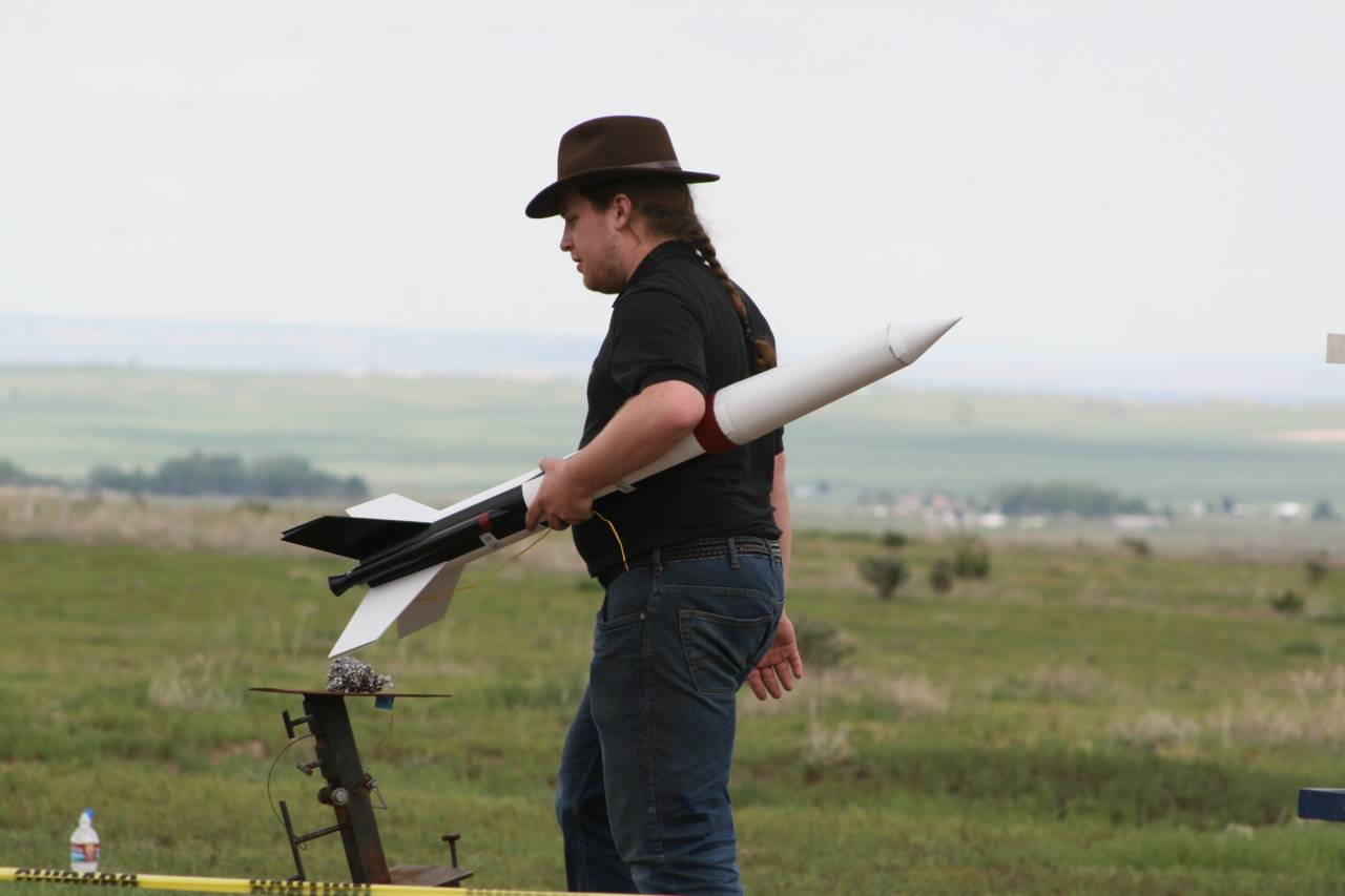
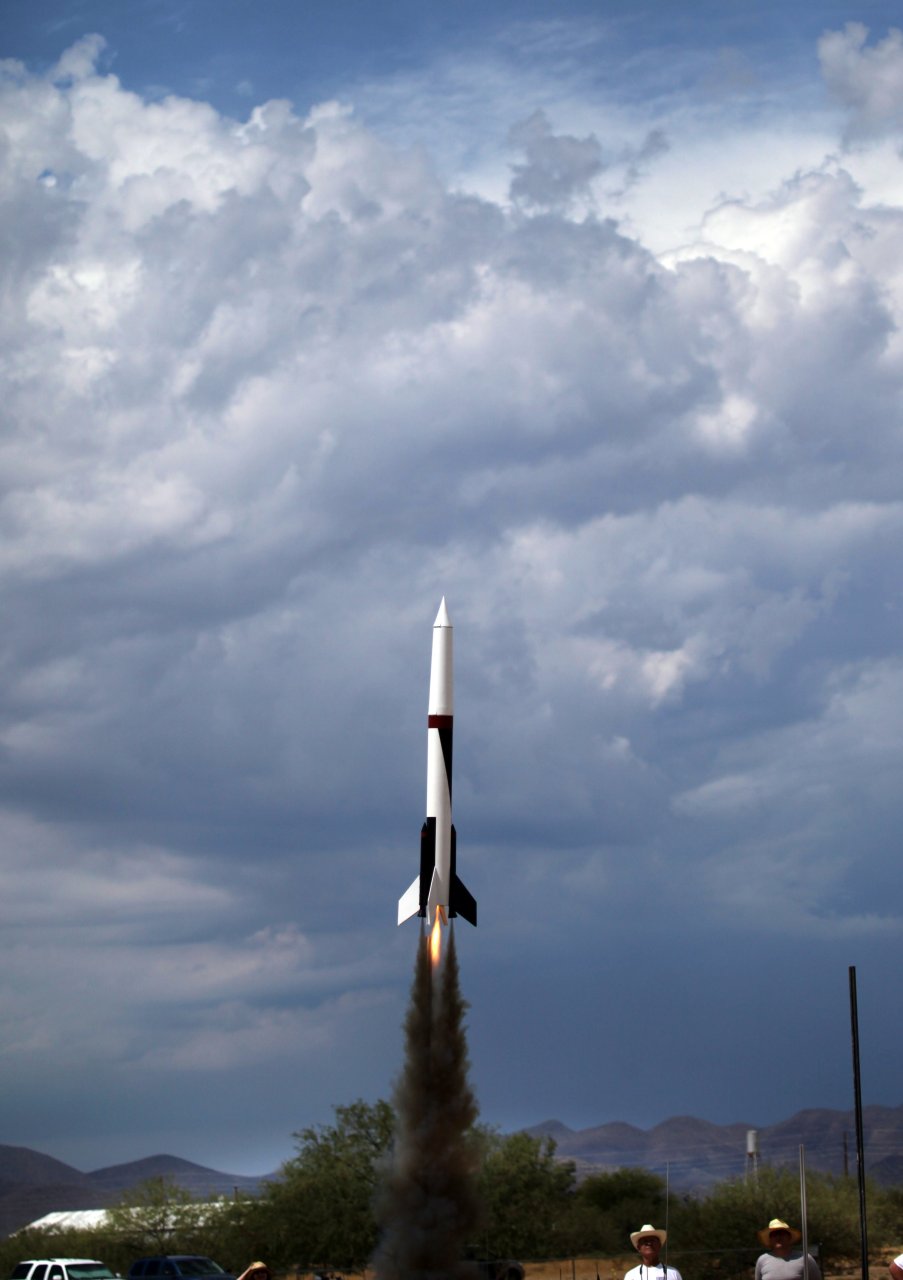
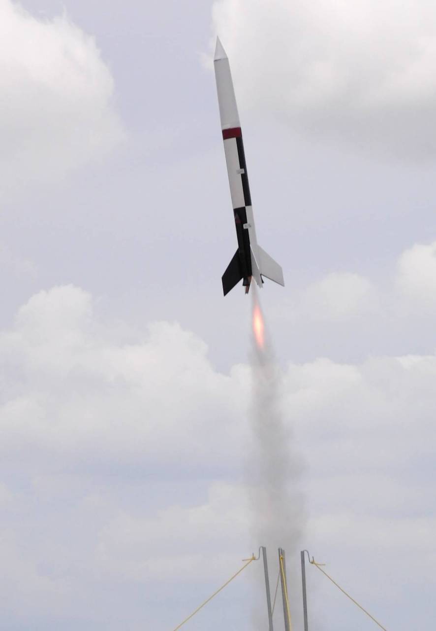
Anyways, without further ado, pictures by Chris Taylor of NARAM Live!
2014-0820%20-%201311.24%20%20CIMG6950%20-%20Copy.JPG


2014-0820%20-%201356.29%20%20CIMG7410.JPG
 
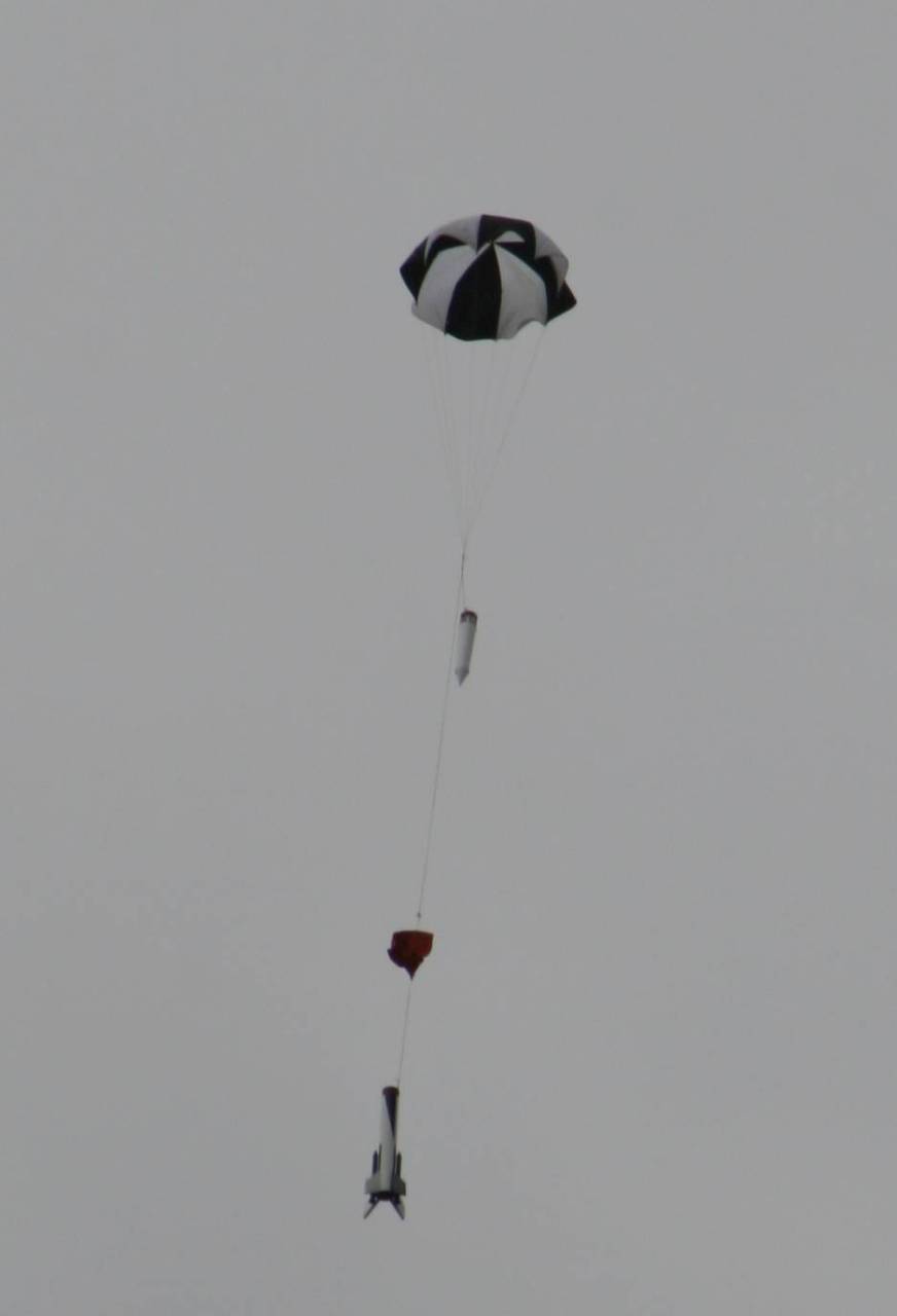
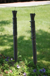
The parachute canopy is actually the cloth from a broken umbrella. The shroud lines are 170 pound kevlar line looped around the widgets that sit on the end of the umbrella structure. Simple, cheap, and effective 60" parachute.

2014-0801%20-%201312.03%20%20IMG_9240.JPG
 
I believe I can elucidate further on the topic at hand.

Thanks to the skill and cleverness of big brother over there, I had the task of piecing together over two hundred individual parts into something resembling an Astrobee 1500. And for some reason he wanted me to paint it too, but more on that later. Click on images for a large size.


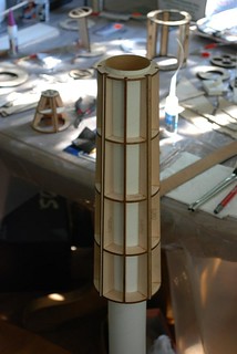
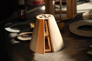
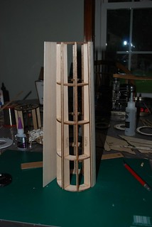
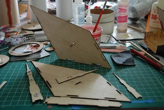
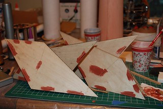
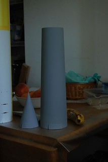
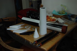
Here you can see the humble beginnings to our Astrobee 1500 - namely, a pile of balsa and plywood. In the foreground two pieces of the nose cone and what would be most of the fairing on the real thing. To keep the shape as close as possible and as light as possible, a page was taken from the model airplane guys and it was built with ribs and formers, then sheeted. The very tip of the nose is a solid turned birch cored balsa cone. I owe a big thank you to my friend bill for making the nose on his lathe since my drill turned noses did not come out satisfactorily. Of the 1480g final weight, the nosecone only makes up about 250g of it! To facilitate alignment between the finished pieces, they were all designed to fit snugly on a BT-70, which also makes up the altimeter bay. While I wasn't 100% happy with my sheeting job, the finishing process made any noticeable (to everyone except me, of course) blemishes in the balsa and curve disappear. Next I tackled the fin can, which is not as straightforward on this model as normal - but as you'll see, that's a good thing.


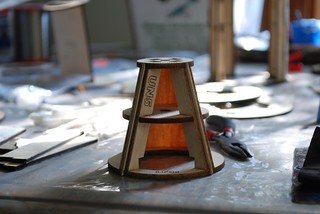
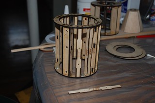
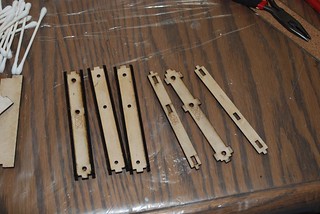
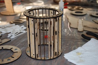
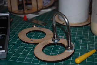
Up first is the fin mount assembly, which also retains the motor mount. This one component handles most of the forces applied to the model, and is appropriately made from 1/8" five ply birch aircraft plywood. The three holes are for two 4-40 machine screws and one 1/8" pin to hold the fins on. The smaller 1/16" ply pieces are for the 0-80 bolts that help to hold the recruit boosters on. The fin mount is designed be removable, but as the first time this model was to be flown was at NARAM-56, I took the safe way out and used wood glue to lock it into the body tube. Note the blind nuts for the motor mount.

Next up is a fin assembly, made up of two skins and four formers. To build they were dry-fit and then a large batch of 5 minute epoxy was prepared (yes, I am very brave). Once the epoxy was ready to be mixed, I removed one skin and one former. The epoxy was then mixed and the formers methodically removed and glued in. Once I was satisfied with the fillets, I replaced the second skin, being sure to avoid gluing it as well, then placed the part under some weights to cure. For the second skin, since I would be unable to fillet the fin when I was done, I again mixed a large batch of epoxy and applied it generously to the center former (where any excess can't be seen, then more carefully scraped it on the inside of the exterior formers. Finally, a thick bead was run down the leading edge to hold it together, the skin replaced, and the whole mess pressed once again. I only had one scare where I had a skin come loose before pressing and it sat on the tabs rather than keying with them. Fortunately, I was able to cut the epoxy and repair the snafu. Whew. After all the fins were cured and solid (very solid) bondo spot putty was applied to the tabs to fill in any large gaps and sanded smooth.

While the Bondo was curing, I took the opportunity to build the 38mm motor mount. In the background of the centering rings picture, the 3" mount tube with thrust ring can be seen. To make sure the thrust ring wouldn't come free, as it is the only thing retaining the mount, the bottom of the tube was sanded nearly to the brown kraft and the inside of the thrust ring was sanded with 80 grit and roughed with a knife. Very thin wood glue was then applied with a brush and the ring seated along the bottom of the tube. A fillet of the same glue was applied after the glue was dry enough to hold. I haven't tested the mount with weights yet, but I suspect it's more than strong enough to withstand at least a medium H. Finally, I put everything together for a test fit; after all, fixing problems is a great deal more difficult once the paint is on. Props to big brother for getting it right the first time!


As I didn't yet have the parts for the recruits (Plan a little earlier next year, guys!) I decided to go ahead on finishing what I did have. The body tube got a solid coat of primer, bondo to fill any remaining blemishes, sand, primer, and three light coats of Rustoleum semi-matte white. The mount holes were made when the tube was bare and cleaned up when the paint cured. When I got the parts for the Recruits, I had just finished up prepping the fins for paint (sanding sealer, primer, Squadron white putty on a few blemishes) and the white paint was dry.

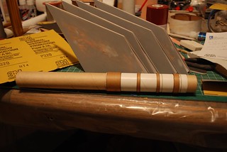
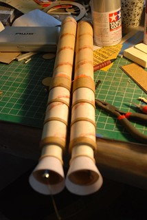
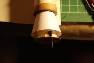
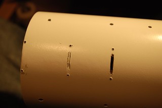
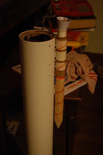
To finish the horrific spirals and surface of the 29mm coupler stock, Bondo alone would be tedious and prone to cracking. Instead, I started by filling the slots to an acceptable depth with thick CA (gap filling glue!), then sanded and finished the spirals with spot putty. The conic transition above the top band is a cardstock shroud, as is the nozzle. The nozzle itself is soaked with CA after installation and is supported by a 1/32" ply centering ring at the base of the 24mm motor mount.

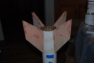
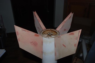
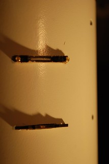
A last minute design change we made was to tab the Recruit mounts into the main airframe instead of relying on the 0-80 bolts alone to hold it. As the mounts are made from 3 pieces of ply, 2 1/32" skins and 1 1/16" core, I made myself a template for the slots by cutting out the center of a spare mount. It worked very well - certainly much better than I could have done by eye. Once the four slots were cut, I assembled eight mounts (four with tabs, four without) and pinned them to the side of the airframe with their mounting bolts. This made epoxying the Recruit on straight a piece of cake. Once both boosters were good and cured, I removed them and finished prepping them for paint.


To Be Continued.....
 
Last edited:


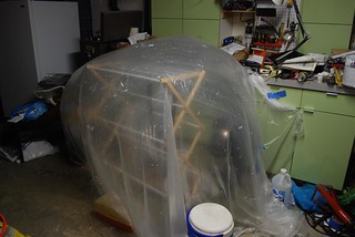
By now I was running short on time - it was Sunday before NARAM and I needed the model out to a fellow rocketeer (Thanks, Rod!) by Wednesday since I couldn't be in Pueblo until Monday morning. The paint can said it had a drying time of 48 hours at 70F in 50% humidity and I didn't have that long. So I did what any good engineer would do; I changed the rules. Using a little ol' fashioned kludge can-do, I fashioned myself a paint drying oven from various household supplies and two 1500W space oil-electric heaters. Now it was 140F and 10% humidity. Perfect!

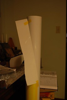
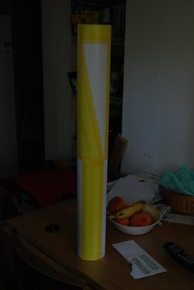
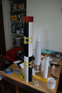
The roll pattern was the most challenging part of the painting. If I screwed up now there would be no sport scale turn in, and the roll-pattern isn't a forgiving one. The triangular pattern also had me stumped for a while before I thought of using a piece of 11x17" paper to draw a straight line between the corners, wrapping the paper along the contour of the tube. Thankfully, Tamiya's masking tape returned crisp lines in spades, and I needn't have worried about the paint. The black pattern was shot with Rustoleum semi-matte black, the red stripes are Tamiya rust red, and the Marmon clamps are Testors silver enamel.

Wednesday morning rolled around and I awoke to eleven dry, painted rocket parts and a few unpainted parts waiting for final assembly. No pressure, right? I started the morning my assembling the nosecone, epoxying the tip on first, then working through Marmon clamp, lower cone, clamp, then finally the shoulder... or so I thought. Somewhere in the build, the holes for the BT-70 nose core had slightly misaligned, and I nearly broke the lower nosecone pulling the tube out. After a minor heart attack, much muttering, and one fewer layers of glassine on the BT-70, everything proceeded smoothly.

I'd believed the worst was over when I finished peeling the last piece of tape on the roll pattern. Not so. As I finished up the nose, I remembered that there were four cradle marks on the side of the rocket where the transporter had rubbed off the paint. I had sprayed some silver enamel on that side of the rocket before the white in preparation for this moment, but as I sat staring at the best paint job I'd ever done, I felt like a real fool for taking 80 grit sandpaper to the side of my beautiful airframe. None the less, I did it and it turned out rather well. At least I got a few compliments on the cradle marks on scale pickup night! For those looking to make cradle marks on their rockets, I recommend no higher than 100 grit. I tried 220 to start with and it took the paint off uniformly, which is not what I was going for. If I had had 60 grit, I probably would have changed to it, but the 80 worked just fine.

After the cradle marks it was all downhill. Earlier I had made the executive decision to epoxy the Recruit tabs and bolts in, permanently mounting them to the airframe even though they're designed to be removable. On went the fins, then the nosecone, and I could finally stand back and admire the hundreds of hours of work to make it to this moment.

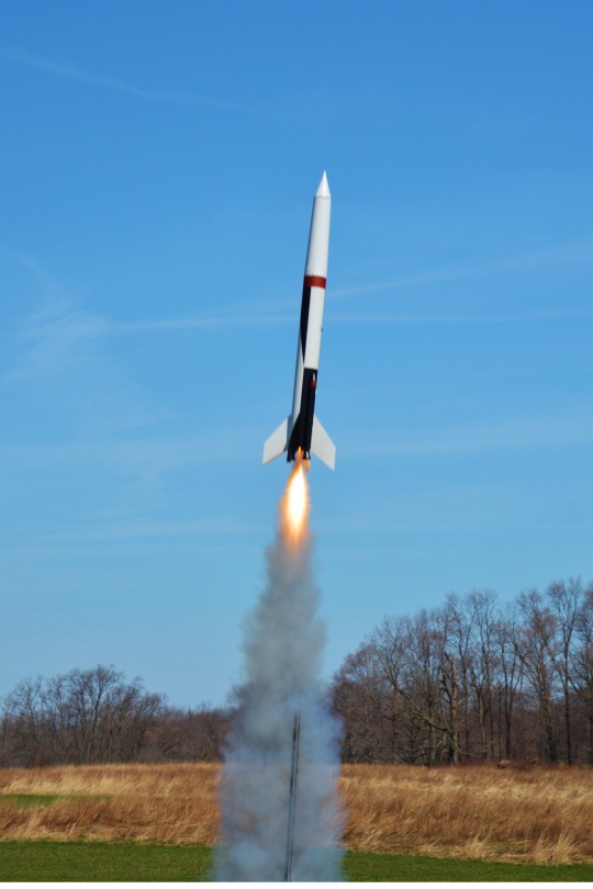
Fourth in static and only missing third by 28 points? I'll take it. At 683 static points, it is also the highest I have ever scored in a craftsmanship event and I am quite proud of this rocket. As first pictures in this thread attest, the flight was flawless. Boost was straight on both motor combos and the built in half degree fin cant made for a great scale-like roll on ascent. There was no damage (one damage point doesn't count) on either flight, and I suspect that this rocket will be a favorite in the sport fleet for years to come. Since we didn't get to fly it on the G58 like we wanted to, I will be adding rail buttons and flying it with the G and two E22s the next chance I get.

Hope you enjoyed this little journey of insanity in scale modeling! This post was sponsored by Bill C., Rod S., Balsa Machining Tubing, LOC Tubing, Du-Bro 4-40 blind nuts, Squadron White Putty, Bondo Spot Putty, Rustoleum paint products, and CTI ignition reliability.
 
Last edited:
A quick flight report for today. I flew the Astrobee 1500 again on a single Aerotech G64-4W in preparation for the spring contest season. There are a couple of regional meets coming up that are holding the sport scale event, and I wanted to make sure I could get a good flight on that motor.

I retrofitted a couple of rail buttons to make launching easier; a white button in the white region and a black one in the black region. A quick drill into the tube at the proper locations, and some CA to harden the hole and they aren't going anywhere. I wouldn't trust it for a big J or K motor, but for a G, it works just fine.

Because this is nearly a full 34" length of 4" tubing, I was worried that the hobbyline ejection charge wouldn't have quite the oomph to push the nose off. As there isn't much space in the red cap for more powder, I installed that first, then cut a small hole in the top. The other half of the red powder container fits right over it, so I put another gram or so of powder in that and slipped it over the first cap. I was rewarded for my efforts with a beautiful "poonk" sound as the nose left the airframe at a nice leisurely pace and the laundry deployed perfectly.

tumblr_nmpp63Plqm1tvejevo1_540.jpg
 
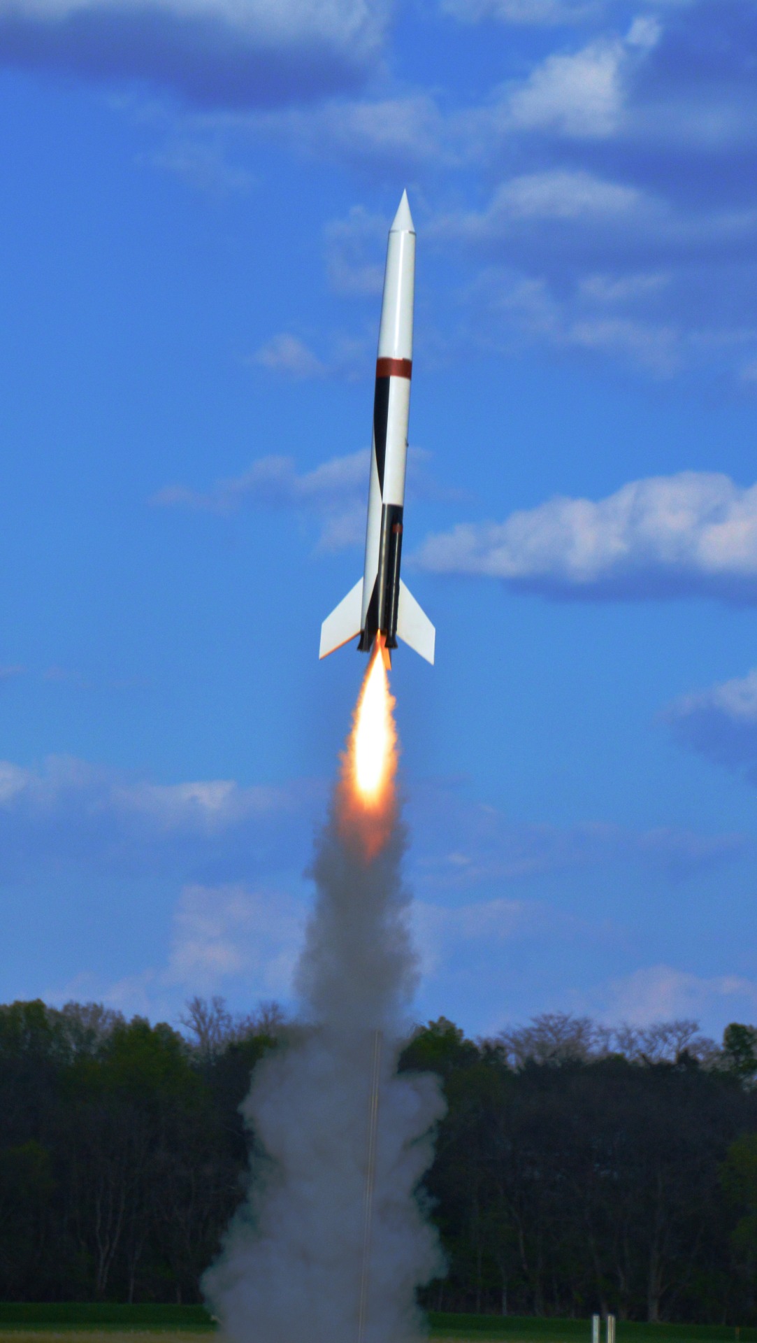
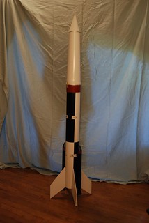
So Sean and I entered the Astrobee 1500 again at NARAM-57 in Sport Scale. This time we decided to go for broke on the first flight and flew a core CTI 53F32-5 and two CTI 24E22-P motors. Per the instructions, we removed the plastic caps from the E22s and dumped the ejection charge so they wouldn't eject themselves from the Recruit boosters.

Anyways, the flight was pretty much flawless with that same gentle roll on the way up. Chris Taylor of NARAMLive! fame got the money shot and managed to catch video at the same time. He uses a large Canon SLI for the still shots with a Samsung Note3 bolted to the tripod mount to get the video simultaneously. Here are the results:

IMG_2611%20-%20Copy.JPG


Flight starts at 0:32.

[video=youtube;GGn9XaBUUJw]https://www.youtube.com/watch?v=GGn9XaBUUJw&feature=youtu.be&t=32s[/video]
 
If I may ask who did the laser cutting for your wood parts?
I would like to build one myself.

I did the laser cutting at a local TechShop-like facility on their cutter. My brother and I recently purchased our own laser and are looking at producing a kit. We are currently working on revisions to bring the weight down, hopefully by about 8oz. This model is very close to the model rocket lift-off limit of 1500g, so some weight savings are in order.

Just out of curiosity, would you be flying as an HPR kit or a model rocket?
I would like to fly it as MPR but I could do HPR if that's what it took.
 
I would like to fly it as MPR but I could do HPR if that's what it took.

The current model flies well on a single Aerotech G64-4 or G40-4, so it can be easily flown MPR if you watch the weight while building. I will keep the forum appraised on the kit status.
 
Flight report: 8/16/15. 2xF30-P, 1x G54-6. First failure to light of a CTI motor and wouldn't you know it it's the core. She went up ~350' and came back down 350'. Sing me a dirge, folks. Pictures will be up soon, but this one is done; the impact partially split a tube spiral, destroyed a fin, knocked off both recruits, and split the nosecone in several places.

At least it's put a fire under me for building a boiler for rev. 3 of the design. Watch this space for more info on the new build and pictures of the damage.
 
Back
Top