So, maybe I'll try a three-stager

The Rocketry Forum

Help Support The Rocketry Forum:

This site may earn a commission from merchant affiliate links, including eBay, Amazon, and others.
I'd love the try the two-stage flight again, assuming it could be approved (it's just a matter of time, I think, before it will no longer be permitted).
Is this just the usual Black Rock launch point issue or something more significant? Didn't make it to BALLS this year so I'm not sure what the Class 3 process is looking like.
 
Is this just the usual Black Rock launch point issue or something more significant? Didn't make it to BALLS this year so I'm not sure what the Class 3 process is looking like.

I'm not sure what you mean by the "usual launch point issue", as the issues were different this year. Further, the conditions for launch this year might have been more restrictive than what actually ended up happening, were it not for some last-minute good work on the part of the Class III committee. My comment is my opinion based on my observations of the process and comments made during the review process. I think getting approval for staged flights over 200K will only get more difficult as time goes on.

Jim
 
I'm not sure what you mean by the "usual launch point issue"...
Basically, that for the maximum waiver you have to launch from the center of the playa, and this is often not accessible and almost never convenient or close to the range head.
 
Basically, that for the maximum waiver you have to launch from the center of the playa, and this is often not accessible and almost never convenient or close to the range head.

Yeah, we were about two miles away. It wasn't a problem as it turned out - no problem for the radios. I can imagine there will be years that the area can't be reached.

Jim
 
Love to see some pictures of your quartz window.

Post #242 had pictures of the bay, showing the quartz window from the outside. It's just a microscope slide glued to the inside of the bay, with the camera butting up against it. The ends of the slide above and below the port couldn't easily be removed, so the repair is just another slide glued over the top of the ends of the original. At some point, I can replace the camera (they still make it), assuming that there is a rocket for the bay to go in to.

Jim
 
Ha must be my old eyes, looked at the one quite a bit and still couldn't see anything that looked like it wasn't part of the lens of the camera. Slick work sir!
 
Today was the kickoff for this year's Balls project. It's going to be (drum roll please)................

A three-stager!

Now, I know what you're thinking. "Jim, you've done that before. Can't you come up with something new?" To that I say, first of all, three stagers are fun! It's as complex of a flight as I can manage and I just can't resist the challenge of it. And, it would be nice to do it right. But just so I can say there's something new, we'll go with bigger motors this time.

So I need to make a new second stage, having lost the previous second stage in the flight this year. It will likely be a very low-tech build - nothing fancy.

I also need to do another test of the stabilization system (I never give up), which has many recent improvements. The test flight was supposed to be this weekend, but the polar vortex is not going to allow the flight to happen. The next opportunity for that might not be until March. Oh, well.

So, that the plan. Time to start building.

Jim
 
So, I've made a little progress on my three stager. The main thing I need to do is to replace the second stage, which includes the 4" to 3" interstage coupler that was lost 1.5 years ago. This coupler uses the 75mm motor tube as the coupler. However, it needs to be designed to prevent turning of the motor tube within the coupler (which would mess up the wiring to the bottom of the 3rd stage motor) and also to retain the 3rd stage motor within this coupler so that the 3rd stage can't drag separate when the 1st stage motor burns out (that would be bad).

As I have done before, the shear pins holding the motor in the coupler will go into the groove for the thrust ring in the AMW motor case. I'm using the same case I used in previous flights, but it was time to replace the epoxy.

The coupler itself is just a glorified motor adaptor. I poured the transition using epoxy and West 410 filler. I like this filler. The resulting material is wood-like and easy to sand, and you can control the amount of filler added (unlike superfil or Aeropoxy light). I just need to do a little pinhole filling and painting, and this will be done.

I poured two of the little epoxy "keys" directly to the motor tube. That will be enough to keep the motor from turning (basically, the whole rocket will be keyed from bottom to top).

The shear pins for holding in the motor have to go from the 4" coupler tube to the 3" motor (i.e., pretty long shear pins). I filled that section of the transition coupler with epoxy so that the pins are guided directly to the motor tube (and I have some long pins for this application). You can see a set of two shear pin holes on the lower left side of the 4" coupler.

Jim

IMG_0954.jpg

IMG_0955.jpg

IMG_0963.jpg

IMG_0990.jpg

IMG_0992.jpg
 
Last edited:
Jim, what epoxy do you use?

I just use West or Aeropoxy laminating resin with an assortment of fillers including the West 404 high density filler, some sort of fumed silica (e.g., West 406 or cabosil), and some sort of chopped fiber (e.g., milled glass). I'd like to start using some of the higher-temperature resins, but I need a new oven.

Jim
 
I've made a bit more progress. With the transition coupler completed, I moved on to the fins. Since the second stage won't require high performance (it stays below Mach 2), the fins can be pretty simple. The basic approach is to start with 1/8" G10, laminate with 2 layers of carbon, and then use 2 tip to tip layers later on.

The fins are initially cut in a delta shape. These will be clipped later on when all weights and such as know so that the stability in the 3 stage and 2 stage configurations can be optimized.

I made a nice jig out of a couple of tiles to bag the fins after adding the laminating carbon. One thing I did was to put a boundary around the lower tile so that the bag material wouldn't get sucked between the tiles. I made this jig out of 1' x 2' tile, since I plan to laminate some larger fins in a few weeks. So, in the first use of this, there was a fair amount of unsupported tile on each side of the pair of fins that was being laminated. As you might predict, there was enough force on the unsupported area that the upper tile got cracked neatly into three pieces. After a quick trip to Lowes, compression resumed (using a smaller tile) and everything turned out fine. I beveled the fins using my router and then sanded them to shape.

Jim

IMG_0998.jpg

IMG_1005.jpg

IMG_1006.jpg

IMG_1011.jpg

IMG_1013.jpg
 
Looks like about 3 weeks since I last posted progress. Since then, I have completed the lower air frame for the replacement second stage. As shown in the first pic, I like to add just a little weight to the end of the cloth as I roll the tube. It just turns out better that way.

As normal, I use peel ply over the top of the layup. I'm not sure if I ever shared this trick, but an easy way to get air bubbles out from under the peel ply is to use the tip of a chip brush. Just tap, tap, tap - it's like magic. Note the before/after pics.

The upper part of the tube is finished while the lower part still has the peel ply finish for adding the fins.

For the upper air frame, I'm going to cheat and use the fiberglass upper air frame from an existing rocket. This is so that I can use an existing altimeter bay. This section is currently the upper air frame of the sustainer on my stabilization system test rocket. I'm planning to fly that one more time, but after that, I won't have much of a need for it. So, I'm just going to re-purpose the parts for the three-stager. I'll probably add three wraps of carbon.

Jim

PS - I was rolling the tube while watching the most recent Space-X launch and barge landing (see the tablet in the first pic). Seemed appropriate.

IMG_1029.jpg

IMG_1030.jpg

IMG_1031.jpg

IMG_1041.jpg

IMG_6398.jpg
 
Last edited:
Hi Jim,

I know I have read this before, likely a few times, but for convenience can you remind me again, how many wraps do you typically do, and what epoxy and cloth are you using? It looks like a twill...3K 2x2?
 
Hi Jim,

I know I have read this before, likely a few times, but for convenience can you remind me again, how many wraps do you typically do, and what epoxy and cloth are you using? It looks like a twill...3K 2x2?

I typically use 7 wraps on a 4" tube, although I might have used 8 once or twice. I use the nominally 6-ounce 2x2 twill, which is relatively inexpensive as a "commodity" cloth. I use the Aeropoxy with 3665 hardener. This particular rocket is not being designed for high performance - that will come next year.

Jim
 
Jim, being the tube making master you are, have you ever looked at a heavier triaxially woven cloth.
 
I haven't seen that stuff before. I'll have to take a look.

Jim

Jim, Soller Composites has it. It is a 12k fabric and 15.6 ounces a yard. It is also 0.022" thick. Might make a really strong tube though.

As I recall, Dave Trianno used it in his Trinity rocket, which was pretty impressive as memory serves.
 
Jim,

I noticed all those fraying strands on the peel ply. Grab a soldering iron and cut the peel ply with it. It helps out a lot.


Sent from my iPhone using Tapatalk
 
I typically use 7 wraps on a 4" tube, although I might have used 8 once or twice. I use the nominally 6-ounce 2x2 twill, which is relatively inexpensive as a "commodity" cloth. I use the Aeropoxy with 3665 hardener. This particular rocket is not being designed for high performance - that will come next year.

Jim

Jim

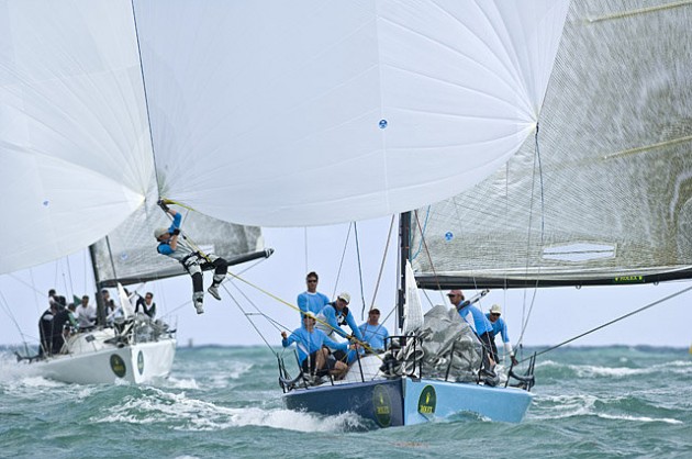
How much do you think that's overbuilt? The reason why I ask is the loads on the spinnaker pole for a 40 foot boat are from all directions and can be both excessive and dynamic (compression lengthwise, tension lengthwise, significant bending forces at the tip, with little internal support such as a motor case), and they get 7 wraps of 5 oz. Have you had one of your carbon tubes fail on you?

hqdefault.jpg


photoweek121508-249-articlefull-0.2490.jpg


Apologies for hijacking the thread.

Chris
 
Jim,

I noticed all those fraying strands on the peel ply. Grab a soldering iron and cut the peel ply with it. It helps out a lot.


Sent from my iPhone using Tapatalk

Well, those are on the seam that isn't in contact with the carbon, but you're right, I should give that a try.

Jim
 
Jim

How much do you think that's overbuilt?

It's always hard after an "event" to pin down cause and effect. I do know that I started having more success above Mach 2.5 when I upgraded the strength of things in general. I'm not sure it's overbuilt at all.

Jim
 
It's always hard after an "event" to pin down cause and effect. I do know that I started having more success above Mach 2.5 when I upgraded the strength of things in general. I'm not sure it's overbuilt at all.

Jim

Jim, thank you.
 
And here's the "glassed" upper air frame. I even managed to find the altimeter bay switch holes! Next will be the fins, but it will be a while before that happens.

Jim

IMG_1042.jpg

IMG_1043.jpg

IMG_1045.jpg
 

Latest posts

Back
Top