N-Decision: 15 inch x15 foot

The Rocketry Forum

Help Support The Rocketry Forum:

This site may earn a commission from merchant affiliate links, including eBay, Amazon, and others.
Jim,

No, I hadn’t. But I want to thank you for this data point. It points exactly to where I want to go. May I ask what foam did you select? And from your experience how important is the core? I mean, do you believe you could have picked out the core and been left with a hollow fin just as robust?

Feckless


It's been so long ago, I don't remember the details. No, there is not a reason to pick out the core. The foam board is virtually no weight, what would be the point?
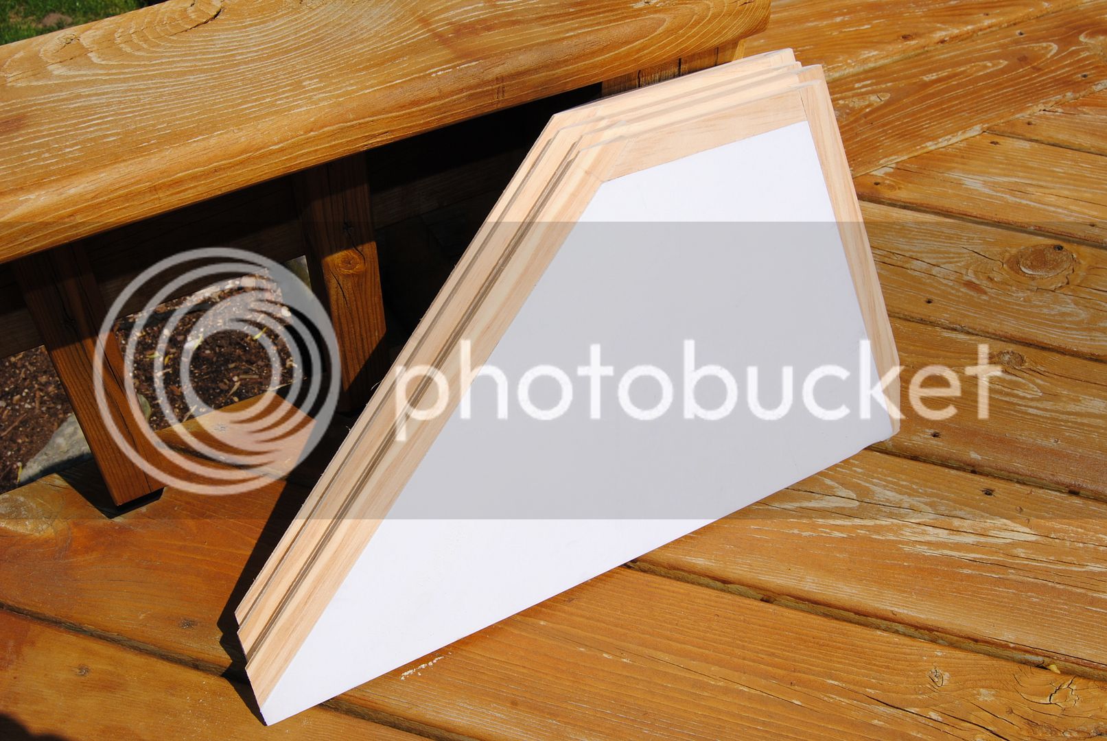
You will note in the pics there were 2 types of F board used, simply because that's what was there. The Purple stuff had denser foam & could not be compressed much at all.

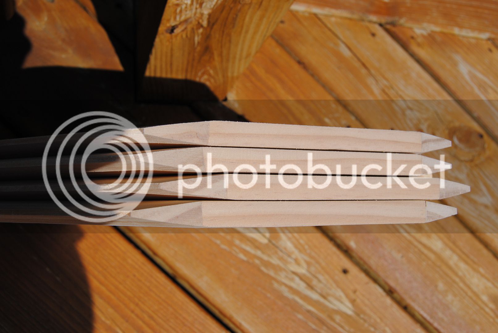
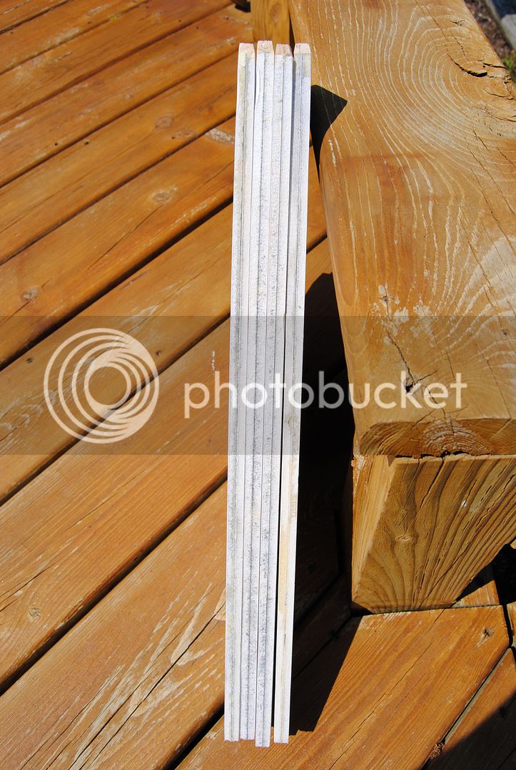
Then when Tim did the "sandwich" version with G-10 sheet blue was used, which I think was obtained at Menard's. I stood on a section of that suspended between 2 cinder blocks. I come in at 215lb & trying to bounce it........would not deflect!

Call him at Wildman, I sure he would give you the details .
 
Let me post a photo or two of the fins I'm working on for an LDRS33/MWP12 project: Hot Topic II. They are two layers of 3/16" Gatorfoam laminated together with a layer of 5.7oz carbon in between. Fin edges are capped in pine to allow for consistent beveling. The outsides will be laminated with 2-3 layers of carbon (just haven't reached that point yet). Will snap a few photos of the fins and post this afternoon.

First tested out Gatorfoam 2 years ago with a long aft swept (flutter prone) fin design and they did great. We'll see how Gatorfoam cored fins hold up to an O25,000 this fall.

-Eric-
 
Jim,

Yeah, sorry for the poorly worded question. Understand and agree there is no need to pick out the foam. Intent here is to understand the foam’s contribution to the overall structure. Does it need to be “special”? But I think you answered that by saying the core material selected is “what was there.” All great experience and guideposts for my project.

Still I’m struggling to know when a particular lightweight solution will “work.” Hopefully, by the end of this project, I’ll have learned how to recon that with numbers. Otherwise I’ll make myself comfortable with the “stomp test.” Perhaps that is as good as needed?

Eric,

Please do share your construction details and any “lessons learned” on this process. That will be very much appreciated.

Feckless
 
Hi Feckless,

Here's a few photos of where the foam core fins for my current project sit.

Side:
081_zpsf9c736e2.jpg


Tips:
082_zps95abfa12.jpg


Root:
083_zpsbd1ba88e.jpg


What attracted me to Gatorfoam was that they advertised the laminates as a stronger, wood based product; as opposed to the glossy plasticized paper stuff typically found on foam board. Strength was/is supposedly superior to the typical foamboards, so I figured I'd try it. I was and am impressed; the stock product is quite strong itself. For a project a few years back, two layers of 3/16" Gatorfoam were sandwiched between single layers of 5.7oz bi-directional carbon with an additional layer of carbon in the middle. I didn't bother capping the ends except for the leading edge w/ balsa. It did well, though the exposed foam melted very slightly where it was most exposed to motor exhaust:surprised:.

For the current project, two sheets of Gatorfoam were laminated together with 1 layer of bi-di carbon in the middle. The fins were then cut to shape and pine edges added to the leading, trailing, and tip edges. I just finished putting the tapers on the fins today. Next will be tacking, filleting, then a total can lamination of all the outer surfaces with 2 layers of carbon.

For simplicity, you can't beat G-10 or plywood. If you're looking to save some weight in the rear end, foam, end grain, or similar can make for some great core materials for true composite fins. Good luck; I'm enjoying following along!

-Eric-
 
TRF,

Following Todd Harrison I’m fashioning this project with a 6-inch motor mount. Can I use PML 6-inch airframe for the motor mount or will that be too snug? I understand there are some differences among 152mm hardware. Perhaps you can advise me on what hardware would be excluded by that motor mount material?

Feckless for Sure
 
Eric,

Really awesome and thanks for sharing. Are you vacuum bagging or is this an open lay-up? If you’re bagging I like to know more about your experience there.

Feckless
 
Hardware built from raw tubing will not fit 6" PML phenolic. The stuff I have/had varies up to about 6.012" and requires honing out 6" tubing. If you're hardware has been machined down to a true 6" OD on a lathe then you might be ok but not many people have a lathe that can do that so the majority of 6" stuff is raw. If it was me I'd omit the MMT tubing and just run with centering rings and make them a tad larger ID than normal.
 
Ethan,

Thanks for your comment and I appreciate the “mountless” design. I have been considering that also. Problem for me is I’m an aspiring flyer at 6-inch. So I will have to think through the 98mm adapter situation. Should be doable, however, and would appreciate any solutions proven by flight.

Feckless
 
TRF,

Had some setbacks at the office but am getting back to this project.
I worked hard to obtain quality end-gain balsa sheet stock in RIGID sheet. The stuff is just not available to my satisfaction. I suspect that quality deficit has to do with balsa falling from grace with the marine set. Tried ordering from three suppliers: one never delivered, the other two sent stuff with voids and gaps between blocks.

Below is a picture of just one of the many voids in material received.

Feckless

Bad Balsa.jpg
 
TRF,

Having failed to obtain suitable balsa I’ve given over to engineered materials. Attached is a photo dossier illustrating my construction of 20-ounce carbon skins over ¾-inch thick Divinycell H80 foam core.

Feckless

A.jpg

B.jpg

C.jpg

D.jpg

E.jpg

F.jpg

G.jpg

H.jpg

I.jpg

J.jpg
 
TRF,

So I’ve been here before. I cut out the fin template and it looks too small. I’ve lost my sense of what’s right at this scale. Looks good in Rocksim’s rendering. It’s stable with good margin. But, ‘ya know, don’t want to cut my hard-won fin stock and end up feckless.

Anyone care to comment on this paranoia at scale?

Fin template.jpg

Fin on ring.jpg
 
TRF,

Trimmed that homemade coupler to length using an overhead router jig. Cuts are clean and square. If you make such a rig I recommend using something stiffer than 1010 extrusion. My rig flexes and vibrates more that I like. Tried to cheap out and am left wanting.

Coupler fits like a dream one direction and is just a snag tight from the flip side. Clearly there is some draft in the airframe. So I’m glad I tried this before slotting. Will have to play assembly with all the basic pieces before picking an end to rip.

Feckless

Trim jig.jpg

Coupler test fit.jpg
 
TRF,

Figured out the draft and what tubes fit on end. Here is the airframe stacked to 118 inches tall and the fin template sort of hanging behind. Comments?

Feckless

Stack.jpg
 
I like it! I need to get over there and see this thing in person!
 
He just bought fiberglass. I'm not sure rattle cans could possibly reach "costing him dearly"!
 
Igotnothing,

Not sure what happened but perhaps you and friends are speculating that I would paint this rocket with rattle cans? The answer is definitely not. By luck I have access to a full-up industrial paint booth. Paint jobs there are always swift and perfect EXCEPT when the operator is Feckless. If you’re interested I’ll take some pictures and make a description of the many problems encountered using nitro paint in the booth. The whole thing really requires constant practice.

Otherwise welcome to TRF and look forward to your contributions.
 
TRF,

All of these work. I'm just sweating the style. Differences are subtle. Any opinions?

Feckless

Well, the most important person to satisfy is yourself. That having been said, I'd go with "A" just because they look proportional. (By the time you get down to "E", IMHO they look small.) Aerodynamically, however, the best option is the lightest fin that will give you sufficient stability. You can get to a point of diminishing returns with larger fins, as the added weight brings the Cg aft, countering any Cp movement advantage.

Always a trade-off in engineering... beauty vs function.
 
SMR,

Thanks for your reply. Your participation in this thread is much appreciated.

So most of the private correspondence on this question has accused me of either making an “eye chart” or posting a “trick question” speculating some of the images are identical. What’s funny to me is children pick “B” almost universally and without hesitation. Adults spend so much time reckoning the difference they can’t make a decision. What have I learned?

Otherwise I believe you are the proponet of “positive” retention. You are not a fan of epoxy fillets against lift / deployment forces. Do I remember your posting such things correctly?

Feckless
 
I believe you are the proponent of “positive” retention. You are not a fan of epoxy fillets against lift / deployment forces. Do I remember your posting such things correctly?

You do indeed, sir. IMHO, I believe epoxy should not be exclusively relied on to carry load, just to keep the physical structures that do in alignment. And there should be multiple paths to distribute the force, so one point doesn't get a focused overload. That being said, I'm lazy and rarely do any of the math, so my builds are usually overweight and never performance optimized.
 
SMR,
So I have given your philosophy some thought. I agree. But to that end I have a dilemma. The attached illustration may aid the description.

Two airframe sections are 59-inches length. The maximum motor length is 52 inches (CTI N3400SK). So that would leave me with 7 inches of coupler length. I might recess bulkheads into that coupler to gain both coupler length and gear space. Then I’m stuck with adhesive joints - no pun intended. That is to say there would be no bulkhead lip riding over coupler's edge.

Important to note is there is no “e-bay” in the traditional sense. Instead there is a box epoxied into the upper airframe having a single breather hole. My greatest fear is coupler bulkheads ripping free and stripping the “e-box” from its mount. Safety first.

My idea is to bolt stops through the upper airframe extending just below the “e-box.” If bulkhead rips through then electronics are, at least, protected onto main deployment. I am reluctant to make longer stops because, as you know, I am watching my weight.

Have you any thoughts?

Feckless

ND coupler Sather.jpg
 
I may be able to solve your problem, but your drawings are "feckless".

Need more details. Can't tell what are BP's and edges of coupler.
where is av-bay? Where is break point for airframe? How much coupler extends into fin can & how much [length ]glued/fastened into payload....if that's what that is.

If you are trying to do a standard DD break between fin-can & payload[which I think is the plan] but there is not enough length in the fin can for motor.

Am I on the right track? If so then.........

Build the coupler like a doughnut. BP's on each end replaced with CR's size of MM tube. Place MM tube sized for Coupler into it You now have 2 mm's The motor runs through coupler & and it still can separate from fin can at apogee. Now you have your bulkhead [CR] lip on each edge of coupler for full support and any length motor can be used [with in reason].

A solid BP can be glued into payload if needed to seal with av-bay on upper side.

If on the right track we can proceed from here...... if not I'm feckless.
 
Back
Top