Next Stop 150k feet: Aluminum Fin Can Extreme Wildman

The Rocketry Forum

Help Support The Rocketry Forum:

This site may earn a commission from merchant affiliate links, including eBay, Amazon, and others.
OK, then another question. I assume there is a secondary step to route out the four tabs (which look solid to me now)?

Yes. He mentioned earlier that he'll machine slots through those tabs to form the flanges that allow all the pieces to bolt together. Note he's making something similar to a Binder Designs fin can. He said he'll machine those slots through most of their depth but leave some material to keep the tube together. Once other machining operations are done he can cut the pieces completely apart. I'd guess his next step is to drill the bolt holes through the flanges.
 
What you see at the end of the tube that looks so thick is actually a fixture to hold the tube. The tube has a 4" ID so wall thickness is around 0.125".

Exactly Right!

OK, then another question. I assume there is a secondary step to route out the four tabs (which look solid to me now)?

Yes, there is.

The secret to machining things accurately is rigidity. That is why I spent a considerable amount of time making the fixture; since the more rigidly I can hold the tube the more accurate, and better end product I will get out of the process. Your rigidity also determines how fast you can machine things. Your mill/lathe could have 1 million horse power, but you would still be limited to the same cutting speed as a 1/4 horsepower mill depending on how well you can hold the part. Chatter is a common issue when you have a poor fixture, since the mill bit bounces the piece you are working on and instead of cutting well, it has a rough and inaccurate surface finish. That said when you can really hold a part well, and have something like a 30 HP lathe you can do amazing things, like cut down the surface of a part and making a 1/4 x 1/4in thick spiral of chromoly steel shoot off the surface. It's actually kinda dangerous to be around since the cuttings weigh a significant amount.

I am saving the cutting of the slots in the three flanges (I only have 3 fins) for last. This is because if I did them sooner my tube would no longer be a tube anymore (a tube is a pretty strong shape), and any further machining processes that I have to do will be compromised.

So the cutting of the flanges is the very last thing, and once I do that they should pretty much fall off of my fixture. The tool that I will use pretty much looks like a tiny circular saw blade on the end of a metal stick. You will see some pictures of it tomorrow when I finish the fin can.
 
Last edited:
Exactly Right!


Yes, there is.

The secret to machining things accurately is rigidity. That is why I spent a considerable amount of time making the fixture; since the more rigidly I can hold the tube the more accurate, and better end product I will get out of the process. Your rigidity also determines how fast you can machine things. Your mill/lathe could have 1 million horse power, but you would still be limited to the same cutting speed as a 1/4 horsepower mill depending on how well you can hold the part. Chatter is a common issue when you have a poor fixture, since the mill bit bounces the piece you are working on and instead of cutting well, it has a rough and inaccurate surface finish. That said when you can really hold a part well, and have something like a 30 HP lathe you can do amazing things, like cut down the surface of a part and making a 1/4 x 1/4in thick spiral of chromoly steel shoot off the surface. It's actually kinda dangerous to be around since the cuttings weigh a significant amount.

I am saving the cutting of the slots in the three flanges (I only have 3 fins) for last. This is because if I did them sooner my tube would no longer be a tube anymore (a tube is a pretty strong shape), and any further machining processes that I have to do will be compromised.

So the cutting of the flanges is the very last thing, and once I do that they should pretty much fall off of my fixture. The tool that I will use pretty much looks like a tiny circular saw blade on the end of a metal stick. You will see some pictures of it tomorrow when I finish the fin can.

OK, with all your discussion about rigidity, my third question... Why cut the pieces apart at all. Not keeping the can intact seems like a big compromise. I can see why Mike at Binder designed it that way for production of reasonably priced parts, but I'd think, if you had your druthers, a one piece can would be far superior. And so that gets back to my other question... i.e., inside machining to get the can to "just fit" the airframe... :)
 
Last edited:
OK, with all your discussion about rigidity, my third question... Why cut the pieces apart at all. Not keeping the can intact seems like a big compromise. I can see why Mike at Binder designed it that way for production of reasonably priced parts, but I'd think, if you had your druthers, a one piece can would be far superior. And so that gets back to my other question... i.e., inside machining to get the can to "just fit" the airframe... :)

Well, there is a bit of a problem with a once piece can, attaching it to the rocket. If you do a friction fit to primarily hold it on like what I am doing with my current fin can, I would need to install that one piece can with a sledge hammer. Or a very large weight. Machining the inside of the tube isn't quite as easy as it sounds. For one I need a large boring bar to be able to reach all the way inside that tube. We don't have one large enough at the current shop I am working at, and to buy one they cost about $2000...

There is a shop in town that I have worked at before that has boring bars and lathes that are big enough to do this kind of work. However they do this stuff for money, so I have to time my work with them in between their paying work. Which wouldn't have been possible in the week and half I've had available to work on this.


So the clamping style that I am using has a massive leap in assembly friendliness since I can replace fins or move the fin can to another rocket in 10 minutes or so. The faces on each flange are precision cut well enough that it should be a pretty solid construction.

I hope to one day get around to making my own motor cases for minimum diameter rockets. My plan was to get an extra thick motor tube, then turn the outside of the motor case down and leave a ledge on the bottom of the motor case. Then my fincan will just slide over the part I turned down and seat itself onto the lip on the motor case. That way the only way my fincan would come off is if it ripped the motor case in half.
 
I hope to one day get around to making my own motor cases for minimum diameter rockets. My plan was to get an extra thick motor tube, then turn the outside of the motor case down and leave a ledge on the bottom of the motor case. Then my fincan will just slide over the part I turned down and seat itself onto the lip on the motor case. That way the only way my fincan would come off is if it ripped the motor case in half.

So, exactly like a Pro98 motor case? They're machined down on the outside.

The other problem with doing slide-on fincans is that when you remove too much material from the outside, the internal stresses that no longer exist now cause the round inner surface to distort. That's not fun to wrestle onto a motor case, and even less fun when you are attempting a thermal interference fit that gets stuck on after half an inch.
 
I hope to one day get around to making my own motor cases for minimum diameter rockets. My plan was to get an extra thick motor tube, then turn the outside of the motor case down and leave a ledge on the bottom of the motor case. Then my fincan will just slide over the part I turned down and seat itself onto the lip on the motor case. That way the only way my fincan would come off is if it ripped the motor case in half.


Check out what John Olevich has been doing (the thread I linked in post #2 here and his other build threads) he has actually machined his own motor cases from thicker stock with integrated fin slots. That's the most elegant solution I've seen so far since the fin-can (or at least the mounting points) and motor case are a single unit, no further worries regarding attachment or separation. Of course you are restricted to research launches once you stop flying off-the-shelf certified hardware.
 
I have been following this build thread and looks great, we have a lot in common! There is also another rocket person I have been following who machined a one piece fin can similar to yours his name is Feretich, I do not know if he is on this forum but if you Google his name with fin can it should come up. His rocket the super-arliss uses a one piece aluminum fin can this is epoxied on to a FW fiberglass tube ( you can use Rocketpoxy or other high strength epoxy and it will hold) he has launched this on N class motors with very successful launches. Below is some photos of his fin can epoxied on airframe. He machined it out of one piece 6061 aluminum (except for the fins which are attached by screws) and slid it over the airframe and epoxied it, quite a neat solution.

FinCanSideView.jpg FinCan.jpg

I myself like to "skip the middleman" and machine a motor / fin can together in one piece, lot of work but works very well and the lines are so clean, and truly a minimum diameter rocket, you are almost at that point. I have not had any issues launching these at any rocket meets I have attended so far and not just research ones, there is a gray area with the "certified parts" as was mentioned above. What I have found is that at a non-research launch the MOTORS need to be from a certified list but not necessarily the hardware. Since I have been using off the shelf "certified motors" I have not had any problems, now once I have said that what and see all the haters here that will email me about how wrong I am, LOL. Best of luck, great to see other rocketeers pushing the enevelope. Some of my latest 54mm fin can motor rockets below, do they hold together? Yes I just flew and won Mach madness contest last weekend at thunderstruck ( 2nd year in a row), 17,000 feet and over 2,000 feet sec, fins epoxied on with Rocketpoxy, last year over 2,700 feet/sec. I am currently machining a 75mm and hope to do a 98mm by end of this summer.

JOHNO_MM10.jpg JOHNO_MM11.jpg
 
Last edited:
Interested in seeing how smooth you can get the bands to come out. Ideally you'd probably want to use a ball nose cutter with a small stepover and that would give a nice radius to your bolt flanges. You've put in an impressive amount of work and thought into this, with this attention to detail I know your cert flight will go well. Good luck to you.
 
I can see why Mike at Binder designed it that way for production of reasonably priced parts, but I'd think, if you had your druthers, a one piece can would be far superior. And so that gets back to my other question... i.e., inside machining to get the can to "just fit" the airframe... :)

Machining the whole thing from one piece of billet would be ideal, but very wasteful of time and resources. 3D metal printing in titanium would be the ultimate solution, but probably won't be affordable for a very long time. If a person was a very good welder and finisher, the result would be nearly as good as machining in one piece. Still more costly than the bolt together solution. The machining abilities of a few rocketeers are impressive for sure, this thread shows that but as you can see from the amount of time invested, it is a labor of love. :)
 
So, exactly like a Pro98 motor case? They're machined down on the outside.

The other problem with doing slide-on fin cans is that when you remove too much material from the outside, the internal stresses that no longer exist now cause the round inner surface to distort. That's not fun to wrestle onto a motor case, and even less fun when you are attempting a thermal interference fit that gets stuck on after half an inch.

That warping is one issue that I am a bit concerned about on this fin can build since I am removing about 70% of the metal from the outside of the tube.

I wasn't actually thinking about doing a thermal interference fit, especially since it might experience some pretty significant heating during flight. Hate for my fin can to come loose mid-flight. I was actually thinking of putting a taper into the fin can and on the surface of the motor. Then just use a few setscrews to keep it from rotating. The taper would be nice since the faster the rocket goes the better the fin can gets seated onto the rocket.

I have been following this build thread and looks great, we have a lot in common! There is also another rocket person I have been following who machined a one piece fin can similar to yours his name is Feretich, I do not know if he is on this forum but if you Google his name with fin can it should come up. His rocket the super-arliss uses a one piece aluminum fin can this is epoxied on to a FW fiberglass tube ( you can use Rocketpoxy or other high strength epoxy and it will hold) he has launched this on N class motors with very successful launches. Below is some photos of his fin can epoxied on airframe. He machined it out of one piece 6061 aluminum (except for the fins which are attached by screws) and slid it over the airframe and epoxied it, quite a neat solution.

View attachment 168554 View attachment 168555

I myself like to "skip the middleman" and machine a motor / fin can together in one piece, lot of work but works very well and the lines are so clean, and truly a minimum diameter rocket, you are almost at that point. I have not had any issues launching these at any rocket meets I have attended so far and not just research ones, there is a gray area with the "certified parts" as was mentioned above. What I have found is that at a non-research launch the MOTORS need to be from a certified list but not necessarily the hardware. Since I have been using off the shelf "certified motors" I have not had any problems, now once I have said that what and see all the haters here that will email me about how wrong I am, LOL. Best of luck, great to see other rocketeers pushing the enevelope. Some of my latest 54mm fin can motor rockets below, do they hold together? Yes I just flew and won Mach madness contest last weekend at thunderstruck ( 2nd year in a row), 17,000 feet and over 2,000 feet sec, fins epoxied on with Rocketpoxy, last year over 2,700 feet/sec. I am currently machining a 75mm and hope to do a 98mm by end of this summer.

View attachment 168557 View attachment 168558

Very nice rockets, I already have a 10 foot stick of both of 2" schedule 80 and 3" schedule 80 6061 tubing, as well as a 3 feet of 3" round stock for my eventual motor cases.

I was originally considering doing the integrated fins to motor case for my cert rocket before I decided to buy my wildman kit. I finally decided that it would be too much of a pain to get everything worked through for concerns about making my own motor case for a cert launch.

Interested in seeing how smooth you can get the bands to come out. Ideally you'd probably want to use a ball nose cutter with a small stepover and that would give a nice radius to your bolt flanges. You've put in an impressive amount of work and thought into this, with this attention to detail I know your cert flight will go well. Good luck to you.

Machining the whole thing from one piece of billet would be ideal, but very wasteful of time and resources. 3D metal printing in titanium would be the ultimate solution, but probably won't be affordable for a very long time. If a person was a very good welder and finisher, the result would be nearly as good as machining in one piece. Still more costly than the bolt together solution. The machining abilities of a few rocketeers are impressive for sure, this thread shows that but as you can see from the amount of time invested, it is a labor of love. :)

Thanks for the luck, I used a standard endmill that was ground into the radius required for the fillets. They came out reasonably good.

Those 3D titanium printers are awesome, I saw one of them at Marshal Flight Center when I was there with my USLI team a few years ago.

I'd disagree with the welding of an aluminum fincan. No matter how good of welder you are you will get a pretty significant amount of shrinkage that you will have to deal with. There is a reason why airplanes are riveted or bolted together. There are a few methods that you can do to minimize the aluminum shrinkage but it is a very difficult issue to deal with. Titanium or steel might be an acceptable material to weld a fincan out of however.

Labor of love indeed, it was about 40 hours total in the last week and a half spent standing in front of the mill or lathes getting this thing done.


And Finally, IT'S DONE!!!

I got all of the holes drilled into the flanges for to attach to the fins. Then I used a endmill and just touched down to the surface to clear away a bit of the fillet in order to give enough space for the nuts.

3cfeb8b9-e704-484c-88c5-b09afa8a6687_zps04687366.jpg


Here is a closeup picture of that end-milling operation.

1148a55e-8b5b-42d2-bc6c-4c38a73b93c3_zps3b30ae43.jpg


Here are all the completed flange holes.

fd1eb900-4f07-4f9c-a5f7-5b217ebea227_zps31d52807.jpg


After I drilled holes into the side which will later bolt to the centering rings, it was finally time to cut the flanges apart!
I had to make 3 cuts with the 1/8" slotting saw to cut the piece out. The first cut was 0.25" from the surface, the second was 0.45" from the surface, and the last was down to 0.550" to completely separate each flange.

645670e6-6474-4cd8-85d4-5610e548d79d_zpsc6bab796.jpg


Here is the second cut down to 0.45", each pass with that slotting saw took 15minutes, so 15 min. * 3 slots * 3 passes = 2 and a half hours of anticipation. I was getting a bit ancy about things, but I willed myself to be patient and not speed the feed on the cutter and risk my flanges getting cut improperly or breaking the cutting wheel.

b8c2961c-d03a-477b-a942-8579919560d1_zps18887c8d.jpg


Here was the final cut separating each flange, you can see the dark void of the previously hidden and unknown inside of the tube.

aae3f2d5-6dc3-408a-b3dc-5ce231196aab_zps9d6b5084.jpg


Wooo! Completed flange! They turned out much better than I could have hoped them to have.

f47e24eb-d6be-462a-988c-12669415710a_zpscc01a07b.jpg


Here is the very flat and even flange surface that my 2.5 hours of waiting got me! :D

c6a89c9b-bb59-428f-ae62-5b345b2e3830_zps0b37c626.jpg


It's actually kinda hard to take pictures of this, its so shiny it messes with my camera.

518fa59c-74f1-4ffc-9476-729c38c4dde0_zpsc01e1dd7.jpg


All the pieces ready, and waiting for assembly.

05978a3d-7c4c-44fc-ab64-88d0e18ede9b_zpsfa6f4acc.jpg


Here is the fincan Mocked up with just two screws holding each fin in. It is astonishingly well held in the flanges just with 2 screws finger tight. This bodes well for the future integrity of my rocket.

a0c4b20b-3855-49da-9e50-262aaba26cd8_zpscf6712da.jpg


The fins are almost perfectly flush with the inside surface. A few of the fins are at ever so slightly different levels since the tube that I had started with started out not very round.

890eeabf-a0c0-4e2a-810b-0115827f29fd_zps91dd35a2.jpg


Here you can see the fillets for the flanges. I started marking which flange connected to each other, but I got so excited that I forgot to finish marking, which is why the flanges are at slightly different hights in this picture. I'll have to do a bit of inspection tomorrow to get them correctly matched up.

a214c1e9-5529-4c9a-a086-fe7cd9d496cc_zps4c778d6c.jpg


Here is a close up of the fillets.

e36064b4-7ca9-4a17-9f7f-59d9ad07abb0_zps3e74e144.jpg


Finally here is the final weight of the fincan; 3.77 lbs. not too shabby, right about where I expected it to be if not a little lighter.

a7536240-3b0e-440c-bdf4-edbedbf0bc82_zps0cd42fa2.jpg


Here is the fincan just stuck on the end of the rocket pieces, its looking pretty promising, I am definitely not going to paint it I like the black fiberglass too much, Clearcoat is a perhaps. There is also a slight chance that I may have held the rocket over my head and ran across the room while making rocket engine sounds... :eek:

2b43712d-e801-460a-a74b-e44dc61c0644_zps232b9080.jpg


Here is the preliminary weight, this doesn't include chutes or anything other than the body tubes, nosecone, and couplers. But at 11lbs that is a pretty decent start on this rocket. I am expecting 15lbs in the end, so any savings I end up getting will be fantastic.

dbf786d8-55d0-4621-a87e-0b971eb3f182_zps61e072ba.jpg


Now all that there is left to do is build the rest of the rocket... Copious amounts of gluing here I come!
 
Last edited:
That looks fantastic! I've never seen a slotting saw like that. I'll have to get one to try that.
 
I'll let the OP summarize whenever he has a chance, but here are a few pics from this last weekend...well done sir! :)

Lake Louise 2014-67.jpg

Lake Louise 2014-68.jpg

Lake Louise 2014-69.jpg

Lake Louise 2014-70.jpg

Lake Louise 2014-71.jpg
 
I'll let the OP summarize whenever he has a chance, but here are a few pics from this last weekend...well done sir! :)

Alaska rocket flying is definitely a different breed. Even hear in MN, snow mobiles are not "standard rocketry equipment". Great job on the rocket. Those are awesome pics. Love the flame color.
 
Alaska rocket flying is definitely a different breed. Even hear in MN, snow mobiles are not "standard rocketry equipment". Great job on the rocket. Those are awesome pics. Love the flame color.

How about the T-shirt in the snow?!?
 
*New Update*

Well it has been a few years, last year I was out of state during out launch season so I didn't have a chance to fly this rocket again last years. This year however I bought a M1297 reload to fly this again during our April launch at Lake Louise.

Over the course of this season one of my freinds suggested that I should build another smaller rocket so I can launch a bit more frequently. So I got to thinking about what kind of rocket I would want to make if I was going to, and I narrowed it down to a minimum diameter rocket of some sort. The next problem is between school, and a major project I am working on that I will detail here at some point, I have very little free time available to work on another project. So if I was going to make a rocket I needed to design the rocket to make it relatively quick to build. The fincan is usually the most time intensive part of the rocket to build, as to get good alignment and good fillets it just takes time. So drawing on my past rocketry history an aluminum fincan is a great solution to my problems. Though this time actually purchasing the whole fincan from Mike this time, and not just the fins. Machining the fincan as I did for my level 3 rocket was rather time intensive, and not very nessisary. I mostly did it for the experience and since it was for my certification rocket. I also don't have as open access to a great machine shop this time around. So pre-purchased it is.

Next I got around to narrowing down what size of rocket to makell; 54mm seemed like a great option as if you add a motor adapter there is a huge range of motors that I can use. So getting down to some simulations and what different motors would do in different configurations; I ended up getting around 22k ft. On a DMS L1000. So then I started to look to see exactly what kind of altitudes I could get out of this, and started looking at my level 3 rocket and a idea formed.

Which brings me to why I am updating this thread, rather than creating a new thread for my 54mm project. I will be converting my level 3 rocket to a booster, then making a 54mm sustainer for a M1297 -> L1000 two-stage rocket.

Overview:

Rocket Design:


Altitude:


Speed:


Booster:
The conversion process for my level 3 rocket is relatively simple. I pull the nosecone off, and swap it for an inter-stage coupler to mate with the sustainer. A bit more complex part is the electronics. The GPS of my level 3 rocket was located in the nosecone. It also had a last minute mouting mechanism made out of a bent piece of sheet metal. All of my push switches have also been damaged due to transportation over the last two years. So I am pretty much going to completely redo all the electronics, along with moving the tragic-little-aerospace GPS into the AVbay with the altimeters. As well as getting around to make a mounting provisions for a gopro camera which I didn't have time to last time.

The last potential change to the booster is to make some experimental antennas like a conformal band antenna for the telemetry link on the gps. I've been interested in getting into antenna design and if I have time I'll design a antenna as part of one of my classes and fly it on the booster to flight test it.

Interstage

I'm still unsure on how exactly I want to make my inter-stage. Machining it would be ideal but I don't have the time or the funds for that. So It will probably be some centering rings and a closely matched aluminum tube that I found from mcmaster to keep everything straight. Then a 3d printed nacelle with some fiberglass reinforcement. For the centering ring with aluminum tube idea; doing a split nacelle with the fins butting up against the end of the booster would be the most sturdy as there would be little moment on the tube. But from an aerodynamics perspective if I am not mistaken, I think having a clean transition with the fins forward would be best. If I go with a 12" aluminum tube I can have 4 or 5 98 -> 54mm centering rings in the booster and still have a nice taper.

I am also unsure if I want to actually us an ejection charge to separate the rockets. I was tentatively planning on just using the engine to separate the sustainer. This would be much harder on everything involved. But with some ablative paint protecting the inside, and some large holes drilled around the bottom of the interstage to relieve the pressure and vent the exhaust gases it should keep it from destroying the interstage. With an L1000 I can pretty much guarantee it will separate. Only downside to this is if there was a bad separation and the sustainer got kicked off at an angle the motor would already be firing so it would go flying off into the sunset. On the other-hand, with the motor running all the forces are much larger so small perturbations wont affect the separation as much.

I know many people here have done multi-stagers before, so if anyone has any thoughts on my plans for the interstage and separation I'd be very interested to hear them.

Sustainer

Material wise I was going to go the same as the rest of the booster, and go with the black filament wound fiberglass for everything. I contemplated carbon for a while, but the radio-opaqueness makes everything a problem.

For the sustainer I am planning on it being multi-purpose. I will probably get two body tubes, one for multistage flight, and one for by itself. The multistage body tube wont have a motor retainer. As for up here, the best motor for our fields is a DMS, so I will just friction fit the motor. As if it does come out it doesn't really matter that much as it is getting thrown out anyway. That will then let me use the bottom 4-6 inches of the airframe to fit into the interstage. I will use the fincan as a stop on the body tube by bolting it 4-6 inches up the air-frame. For the standalone body tube I will glue a motor retainer on it so I can use it with any motor; and some conformal rail guides. Then all I have to do to transition between configurations is swap the fincan over and voila.

I was planning on only a single deployment, and use the new fangled jollylogic chute deployers to provide the dual deploy functionality. This keeps the required length of the rocket down as much as possible.

For avionics, I was going to go with a Telemega for all the primary functions, including GPS tracking, motor ignition, recovery deployment. I will also put in a stratologger as a backup for deployment as I would really like to at least have an opportunity to get my $550 of electronics back if something goes wrong. The avbay will be the nosecone with a 4 inch body extension and as well as the 4 inches of transition. This will give me 8" plus the nosecone, which is plenty of room to mount the electronics and a gopro or two. To run the wires to the motor from the telemega to the engine; I was planning on using two strips of copper tape on the exterior of the rocket, to do a majority of the run. With some strategic kapton and masking tape put over it to protect it from the airflow. The deployment will tear the copper tape easily, and I can soldier the ignitor wires and the wires to the telemega at each end.


That is the basics of what I am planning, I am sure some things will change as I realize what a fool I was. The fincan is already purchased from binderdesign, and I am shoring up my ideas on everything before I put in the purchase for the body components from wildman.


Bonus Points:

I simmed the rocket with new body tubes to fit a Loki L-2050 in the sustainer, and a CTI O3400 in the booster and got some interesting results.


All I would have to do to make the transition is buy longer body tubes and swap the fincans over. Anyone want to team up with some EX motors at Balls this year? :)
 
Wow! I can't wait to see this started. This whole thread was very interesting, just read it from beginning to end. :D
 
I'll let the OP summarize whenever he has a chance, but here are a few pics from this last weekend...well done sir! :)

Now, THATS an igniter... a poof and you're already 2 feet off the ground?! :cyclops:
 
*New Update*
I only just found this thread, thanks to the recent updates. I love the fin can. As to the two stage...

Which brings me to why I am updating this thread, rather than creating a new thread for my 54mm project. I will be converting my level 3 rocket to a booster, then making a 54mm sustainer for a M1297 -> L1000 two-stage rocket.
When I first saw the picture of the two stage configuration, I thought the original 75mm was the sustainer, with a 98mm booster. Mwah-hah-hah!

I simmed the rocket with new body tubes to fit a Loki L-2050 in the sustainer, and a CTI O3400 in the booster and got some interesting results. [Graph showing 148,104 ft.
Holy feces! That's about 45% of the way to space. You must. You really must.
 
Wow! I can't wait to see this started. This whole thread was very interesting, just read it from beginning to end. :D
Very interesting. Subscribed.

Thanks guys; Very Interesting is what I said too when I started to see the sims. :p

I have all the parts including the electronics on order, wildman said the air-frame parts are on their way; so it should be a waiting game till everything shows up. It's like having to wait for Christmas when you were a kid all over again.

Now, THATS an igniter... a poof and you're already 2 feet off the ground?! :cyclops:

I used two pyrogen igniters, I cannot remember the brand off the top of my head. The pyrogen comes cast in drink straws if that narrows it down.

I realized that I have never posted this video in the thread. I didn't get the footage together until several months after I launched. Sadly no sound on the video but, it looks cool anyway.

[YOUTUBE]R3_7GmNNDPk[/YOUTUBE]


I only just found this thread, thanks to the recent updates. I love the fin can. As to the two stage...

When I first saw the picture of the two stage configuration, I thought the original 75mm was the sustainer, with a 98mm booster. Mwah-hah-hah!

Holy feces! That's about 45% of the way to space. You must. You really must.

Thanks! The level 3 rocket is a 98mm airframe, so I think I would have to stage from a 152mm booster to 98mm sustainer to keep the proportions right. :cool:

I am pretty tempted to try the high flight, all the systems required will have been proven out by this lower altitude launch.

I would have to partner with someone to do an EX motor for the booster, as I can't ship EX motors down to blackrock from Alaska. I also couldn't afford paying the $800 ticket down to Blackrock + chipping in on a RV rental + $800 for the loki motor/case, then having to pay $2k for the O3400 reload.

Though if you find that interesting; you will be very interested in when I post about my other project I have been working on for over a year now; that I will post about on here on a yet to be specified date. :wink:
 
Thanks guys; Very Interesting is what I said too when I started to see the sims. :p

I have all the parts including the electronics on order, wildman said the air-frame parts are on their way; so it should be a waiting game till everything shows up. It's like having to wait for Christmas when you were a kid all over again.


I used two pyrogen igniters, I cannot remember the brand off the top of my head. The pyrogen comes cast in drink straws if that narrows it down.

Twas a joke aimed at the height of the rocket (where your standoff was) ;)
 
Twas a joke aimed at the height of the rocket (where your standoff was) ;)

Hahaha, the hazards of sarcasm over the internet! I was like man, I didn't think those igniters I used were much out of the ordinary... :p

My first launch was off of Lynx Lake, Alaska many cycles ago.

Which Lynx Lake? If it is the one on the Kenai peninsula that seems like a bit of a random lake.
 
I have all the parts including the electronics on order...

Lake Louise is one month away! That means you've got another three weeks or so before you really need to start building :p

Just kidding, I didn't realize you were back in state-- I'm heading to LL too, it'll be great to catch up and see this beast fly!
 
Lake Louise is one month away! That means you've got another three weeks or so before you really need to start building :p

Just kidding, I didn't realize you were back in state-- I'm heading to LL too, it'll be great to catch up and see this beast fly!

Well normal schedule is start construction at 1am the evening before the launch, and finish drilling the last vent hole on the pad. So I pretty much have ages. :wink: Been meaning to get a hold of you for a while, Look forward to seeing you at the lake!


So for a small update, I have been getting parts in slowly, I got the fin-can, and most of my electronics in. The box from wildman with all my parts in it has been going through some drama with the post office, if I can't figure out where it is tomorrow, I'll reorder and see if they will take a return if it does show.

The fincan from Binder Design is gloriously pretty. The fins are so nice I am almost scared to fly it as to keep from scratching it. I think the pattern I chose for the fins matches my original fincan well. Except now I need to polish up my fincan as it looks like a beat up wreck in comparison...


And one more photo of the fincan for good measure!

 
Things just got interesting... Finally...

Took a bit of time, but I finally have all the parts I need to complete the construction of the rocket now.

One of the things I am pretty happy about (for now) is my sustainer separation and recovery scheme.


I just got these two baddies from McMaster...


Is my devious plan starting to come together?

Here is a sequence of what theoretically should happen.

Nominal Boost:


Sustainer Separation:


Apogee Separation:


Keep in mind I haven't cut the body tube to length yet, the real separation point will be about 12 inches or so from the bottom of the nosecone.

The 2024 aluminum interstage tube turned out near perfect. Has a very decent fit for a standard extruded tube. It will only need a wrap or two of masking tape to tighten everything up nicely.


The separation actuator when I use smokeless powder should have about 400 lbs of separation force. Should be plenty to get them apart. My apogee separation actuator will have about 250 lbs of force. Main reasons for using the pneumatic actuators is A: I wanted something that would be insensitive to altitude, and two I wanted something that would isolate my parachutes from the ejection charge heat completely. I am also pretty happy with how light both actuators are, it is a bit heavier than a normal ejection configuration. But I think the increased reliability and higher force is going to be nice.

It also is a prototype test for recovery system ejection for other projects I am working on.

All that's left now is to build the dang thing! I'll actually post some build images of the rocket this time, not just the fincan like I did for the booster.
 
Last edited:
Update on current progress:

Project update time. First of all, my launch at Lake Louise ended up being a bust. Didn't have the electronics bay completed in time and was working on it in the cabin at the 11th hour, trying to get it together (seems to happen to me on occasion). Didn't quite manage it to a level I was comfortable with, also the winds blew hard during all of our high altitude windows anyway. No one was able to do any real high launches that weekend. Butter luck next year on that front.

As far as rocket construction goes physically the rocket is complete aside from the electronics bay. I'll post an update on the build progress that I made either at the bottom of this post or in a few days when I get a chance. I will however add a picture of the finished product right now, and backfill in the details of what I did later.

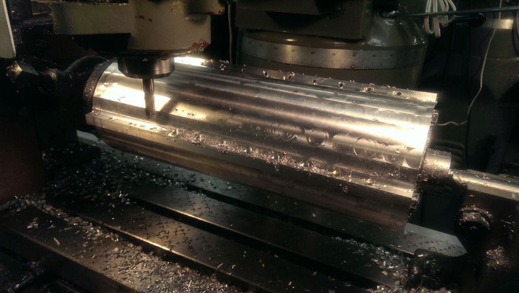
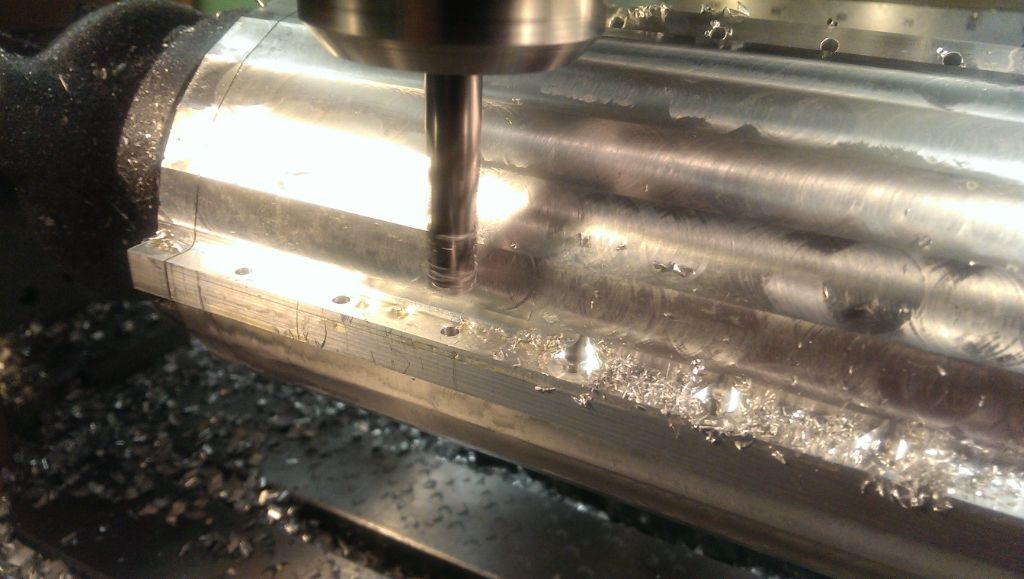
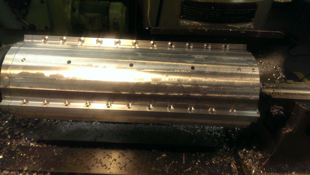
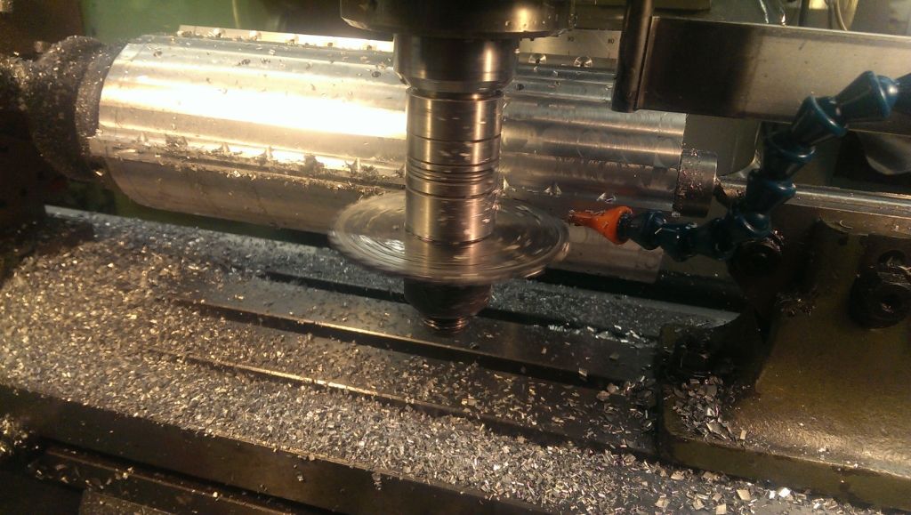
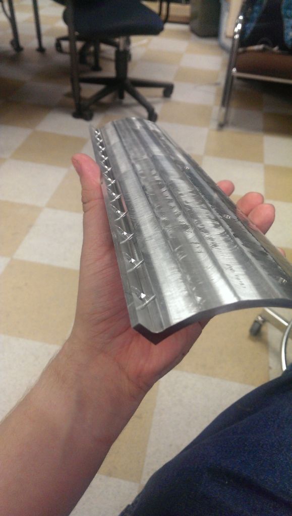
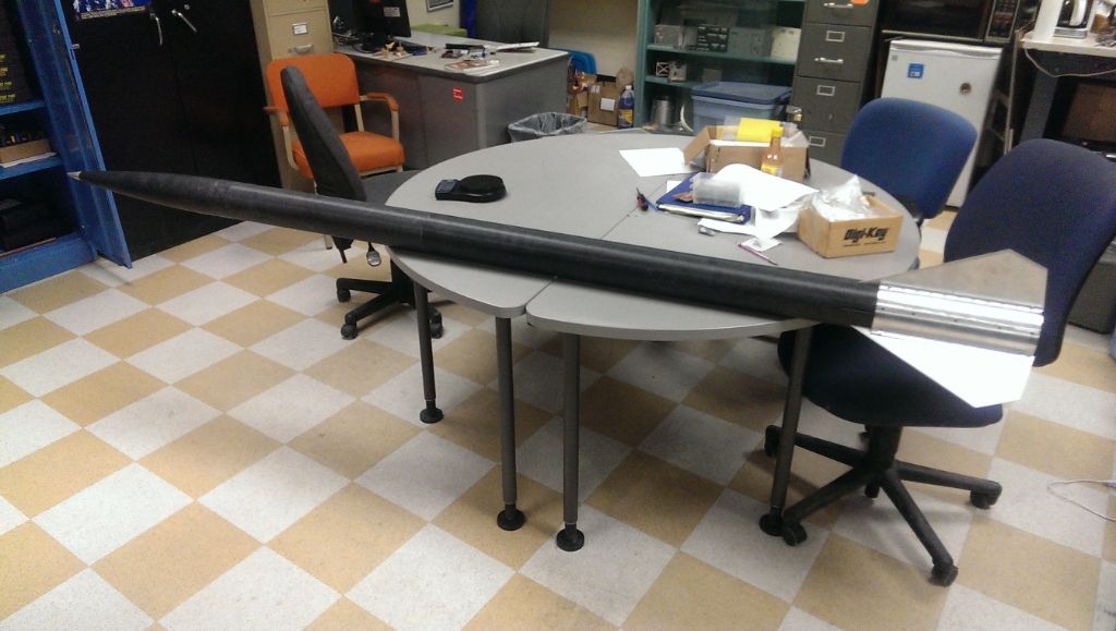
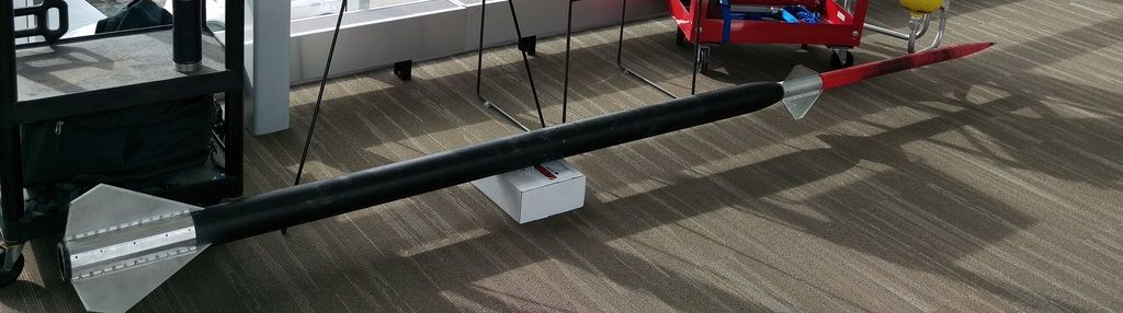
So here is the current state of things!

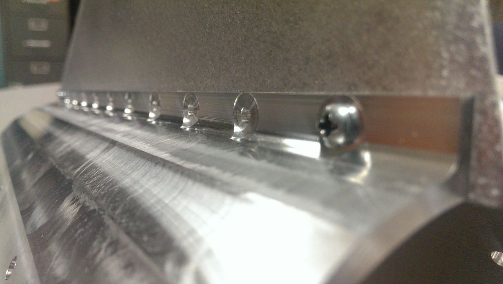
This is a little bit old, there was lots of work done on the sustainer after this was taken.


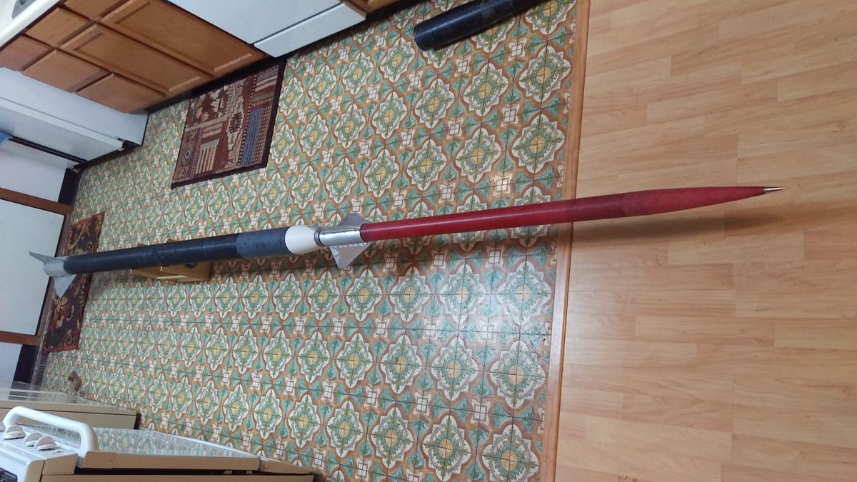
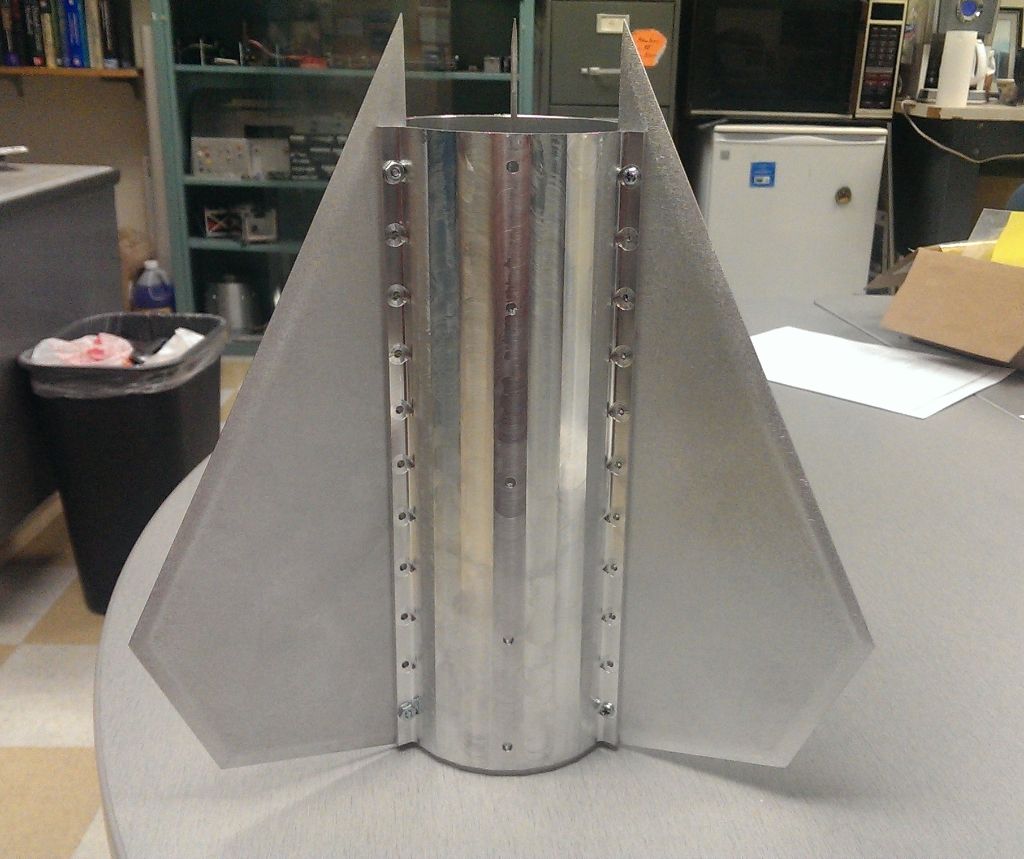
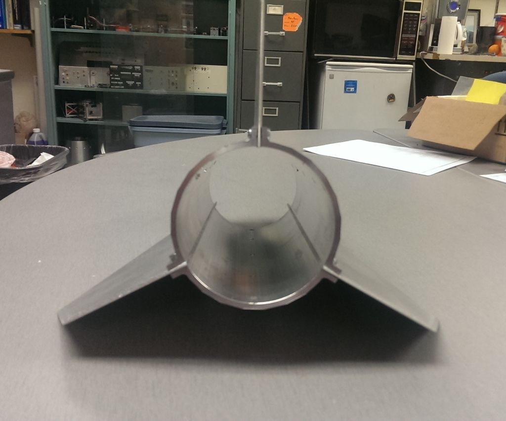
Here is a picture of the completed product, with everything except for the electronics bay.


New Project Goal:


Now for the new and exciting news. Since I restarted this thread Scott from Loki Research and I have been collaborating on teaming up for possible EX motors for this rocket to fly at BALLS this year. Recently things have fallen into place, letting us pull the trigger on the teaming. So now the next plan is to fly this rocket at Balls this year, and try to hit 150,000 ft.

I would have preferred to have gotten a flight in to ~50k first on the rocket. I don't particularly like pushing the boundaries so much on an untested system. But sometimes you just have to take the opportunities that you get. This does mean I'll be doing a bit more ground testing of systems than I would have normally done. After-all I'm only increasing my personal previous max altitude by an order of magnitude, what's the big deal? :p

The motors we decided on are a 98mm O-2650, which will be run in a CTI 98mm 6GXL case for the booster. Then a 54mm ~M-1400 in a Loki 54/4000 case for the sustainer.

So the general idea is to pack as much motor as possible into each stage and see what happens. It's going to be a bit more complicated than that in practice of course. There were some ideas floated around for even larger motors but keeping the time that is left in mind, these were safer options to fly without being able to do much motor testing.

Here are some conservative preliminary simulations on the rocket's performance:


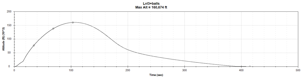
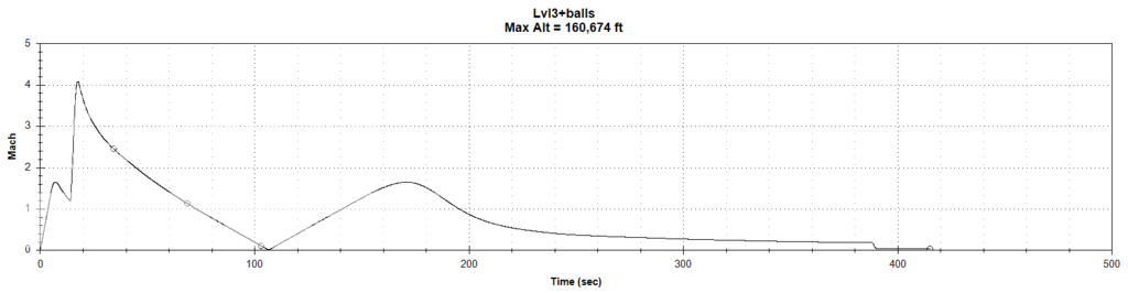
The real value is going to be quite a bit lower, since the sims are not taking into account some fairly large sources of drag that are present on the actual rocket. I am planning on going through the rocket doing some drag reduction procedures.


There is a bit of work that needs to be done to get the rocket ready for a launch like this. Largest item is I need to swap the fincan over from the current 76mm motor mount tube, to a longer 98mm motor mount tube.

Here is the list of things I am planning on doing:

Structure:

- Replace booster motor tube with a 60" 98mm fiberglass Motor tube
- Replace current fiberglass sustainer motor tube with a 60" 54mm carbon fiber tube
- Apply 1-2 plys of kevlar to sustainer avionics bay and nosecone
- Complete 3d printed avionics bay sled
- Apply Dow Corning 3-6077 ablative to high heat load areas.

I'm fairly certain the booster will be just fine staying as fiberglass and in its current configuration. The booster has flown to mach 1.5 and 15k feet as my level 3 rocket. The O motor we are using doesn't have a whole bunch more thrust than the M1500G that it has flown on previously and the speed peaks out at mach 1.6. So I think the fiberglass can handle the new aeroloading just fine. The extra ~20lbs of weight on the nose of the tube is a new one however. I am not entirely sure I am going to fly the booster as a Dual Deploy. I'd like to remove one joint to make the rocket motor rigid overall, and just deploy the main parachute at apogee. Since we are at blackrock I think there should be plenty of space to recover the booster even if I deploy the main chute at ~14,000 feet. My chute size makes the rocket come in a bit hot anyway since it was designed for landing on snow. I'll be doing some more sims on it to see exactly how high my booster is going to go before I decide.

I want the extra rigidity since small perturbations on my boost phase I am pretty sure will have some pretty large results on my sustainer in bringing things off course. The added weight of the sustainer and interstage is also going to make things more wobbly than they were with only a nosecone on the top.

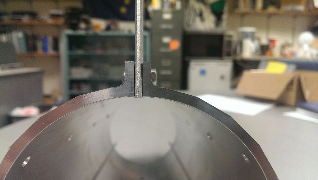
The sustainer I know I need to beef up, the fiberglass tube is pretty thin, and a bit marginal for doing above mach 3. At mach 4+ I need to do more. For the motor tube I am planning on replaceing the fiberglass one with a carbon fiber tube, to give me extra safety margin and lower the weight as much as possible. My electronics bay needs to be radio transparent, so I am planning on reinforcing the existing fiberglass with some Kevlar. I'd like to overlap the Kevlar over the aluminum nose tip. I currently have it potted in JB Weld to keep it from moving, but I really don't want this rocket to fail because the JB weld softened and my nosetip fell out of alignment.

Then to keep my composites from peeling from the mach 4+ at 27,000 feet I am going to put 3-6077 ablative on the forward exposed surfaces. I still need to investigate its post cure work-ability and if it is still radio transparent even when charred. As if the radio transparency goes away I will have to reconfigure my av bay to move my antennas out of the nosecone. I know the stuff will be more than sufficient for any heating loads I would get. The other application I know it is used in protects very well against from getting hit by a 250,000 lbf solid motor exhaust from 1 foot away. I cant imaging any kind of aeroheating that could be worse than that so it should be just fine in this application.

Electronics:

I do need to revamp my telemetry link some. At 30 miles for apogee the wire antenna and 89mW transmit power out of the telemega isn't going to cut it. I could get a more directional receive antenna, but if I lose sight of the rocket (which I will trying to find a tiny 54mm dart at 150k feet) I can eaisly lose track. So my plan is to add in a power amplifier, dipole antenna (doesn't need a ground plane), and a Z match to boost the transmit power of the telemetry unit to at least 1000 mW.

I am also planning on boosting the receive side of things as well, perhaps an omni ontop of a long pole. It would be nice to be able to get GPS tracks when the rocket is on the playa; which from my understanding is a pretty serious radio attenuator. I'm planning on doing some testing up here before I go down to see what my receive range is, that will help me determine if I can get away with an omni antenna atop a tall pole, or if I need to get a more directional yagi to make it work.

The M-1400 will be head end ignition which is going to simplify my wiring issues.

I'm currently working on getting my class 3 packet together right now to submit as soon as I can. I want to get it in as far as I can ahead of the deadline.

Whatever the result this should be a rather interesting adventure!
 
Last edited:
Hahaha, the hazards of sarcasm over the internet! I was like man, I didn't think those igniters I used were much out of the ordinary... :p


Which Lynx Lake? If it is the one on the Kenai peninsula that seems like a bit of a random lake.
The one up by Wasilla. It was a fair trek back in the day as the road in was really poor.
 
Alright, this will probably be my only update until BALLS, unless I get board waiting for the plane. But first I'll put out the pictures!


First I'll go into some historical stuff that I haven't posted yet:

Here is a drill jig I made to widen the centering rings I got for the transition.


The cuttings were nice and consistent so I think my jig is working.


The fit around the 2024 aluminum tube turned out quite good!


Next is gluing the centering rings onto the tube with some allthread holding everything together. I put it on a rotisserie to keep everything even. The separation piston will have around 400 lbs of push force which is transferred into the all thread and into the centering rings. So this bit has to be pretty strong.


Another image of it on the rotisserie


Here is the 3d printed von karman ogive transition aero shroud. It was printed in ABS at around 70% density. Took nearly a day to print.


It fit with the airframe quite nicely, and I have it showing where the aluminum part sits in the airframe roughly.


The transition has been glued together here, I have the separation piston with the pusher installed. The maximum extension sticks out of the front so this should guarantee it will get separated.


Coating everything with JB Weld for strength, also it lets me sand it smooth. The final result after we painted it ended up being nearly seamless.


Now onto the New construction!:

First here is the current status of the sustainer. The hole under the nosecone is for the GoPro Black to peek out of.


First the section of airfame that connects the electronics bay and the motor tube was wrapped in carbon. I didn't get any inprogress shots but here is it out of the vacuum bag.


Next I cut the ends off and test fit it where it is supposed to go. The carbon came out really nice, very little sanding was required and only one seam from the bag.


Here it is sanded with 220 grit and resin wiped. Came out rather shiny, and carbonfibery... (carbonfibery is definitely a legitimate adjective. )


Next was moving on to the actual airframes. I first did some bondprep on each airframe, the airframes were 5' fiberglass tubes from wildman.


After this the carbon wrap was applied with the help of some of my friends. The carbon isn't full length as the bottom needs to fit the diameter of my fincans. Plus there is a motor case going at least 40" up each airframe so a little exposed fiberglass on the end isn't a big deal.


Here is putting the bleedercloth on the layup right before putting the vacuum bag over it.


Vacuum pulling down on the bag, she is looking pretty nice already!


Closeup of the bag, and the excess resin being pulled out of the layup.


Here is the finished product.


Turned out really nice and consistent, not much sanding will be required for it to get it nice and smooth.


Here is the finished booster airframe in it's final height. This rocket has gotten rather large...


Here is my polycarbonite window band, I will glue and screw it down soon so there won't be a gap. Took quite a few tries to figure out how to bend it like this.


The almighty CTI 98mm 6gxl case next to the mocked up rocket. The rocket to the right is my freind's BALLS project he has been working on at the same time. The second stage of mine is drooping as I haven't taken up the gap in the interstage with tape yet.


Continued... (ran into image limit)
 
Last edited:
Back
Top