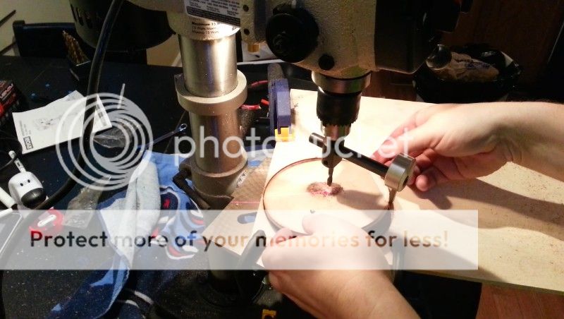
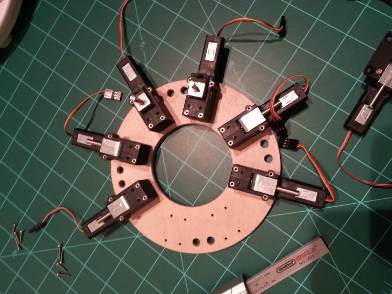
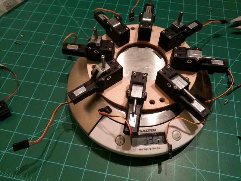
About deploying the motor/prop booms by using retract servos:
Are you using just the servos alone, for locking out the booms at full deployment?
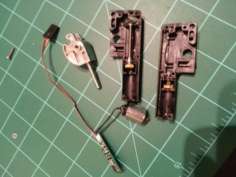
It is easy to strip the gears of servos, unless they are metal gears (with metal gears, harder to strip, but still possible). I'm wondering if the extreme leverage , plus extreme mass of the booms with motors and props at the ends, may be too much for the retract servos to handle. Because those retract servos are used for very short gear legs, with relatively lightweight wheels, with the gear mechanism designed to take the landing loads and for that gear mechanism to take most of the loads that try to fold the gear back up. So the servo is mostly used for moving the relatively lightweight short landing gear up-down, but not for structural loads.
At the very least, you would probably want to have the booms "lock" at full deployment. Could be as simple as the booms hitting a "bumper" so they cannot extend any farther up. Or use some Kevlar cord running diagonally from a few inches from the hinge point, so the line acts like a guy wire to stop the extension.
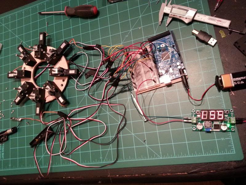
Back to the retract servos, you might want to program the Arduino to slow down as the servo reaches full extension, so it would not come to a dead stop at a fast speed, possibly damaging the servo or over stressing the hinge assembly. Might also want to make it start the deployment a little slower (ramp up the speed) so that there is less stress on the servo to get the heavy motor/prop at the end moving.
Sort of like slow, faster, faster, really fast for most of the travel, start slowing a bit, slow, very slow, stopped at full deploy.
And for preparing for flight, you probably want it to retract really slowly as you make sure all the props are aligned. Possibly even retract one by one, as I could see it being tricky to have all 8 props aligned at the same moment if all 8 booms folded at the same time. Maybe even two little pushbuttons on the model surface: "Retract slow", and "Stop retract and move back the other way" to help with the prep (I have a chart reorder project, with a stepper motor that drives the paper. I am so glad I added the capability to press a button to make the thing back itself up when the paper drive is jammed and I need to undo it). Or perhaps a low-tech solution, small rubber bands to hold the props aligned properly for folding, then remove or cut away the bands after folding for flight.
Actually, I wonder if you really need 8 retract servos. Lots of people fly rockets using helicopter recovery (autorotation), where suitably strong rubber bands pull the blades out once the blades are released for deployment (most use a burning thread for release. you could use one servo to trigger a latch to let go of al the blades). A more out of the box method would be to use a continuous rotation servo with a spool on it acting like a winch drum, to pull 8 kevlar cords. Those cords would go from the bottom up near the nose cone, and exit the cone thru 8 holes, with tiny pulleys (or perhaps simply rounded grommets if there would not be much friction), so the cords could pull the booms up and out. However, there would be a need to add some little standoffs near the hingeline, to help give the pull cord some leverage to begin the early deployment.
Here are links for one of my helicopter recovery designs, on two pages. you can see how it uses rubber bands, and the standoff that is needed for leverage:
https://georgesrockets.com/GRP/CONTEST/Plans-C/Copter/Rotaroc_13mm_1.gif
https://georgesrockets.com/GRP/CONTEST/Plans-C/Copter/Rotaroc_13mm_2.gif
And a page I put together showing how to build it:
https://georgesrockets.com/GRP/CONTEST/Plans-C/Copter/CopterPlan/Rotaroc-A.html
Your model is totally unique. But they do share the same basic problem of how to get long objects to deploy and lock out. Although for one this big, perhaps the retracts are best. But if you did a smaller one, you could consider doing a lighter way to get them deployed.
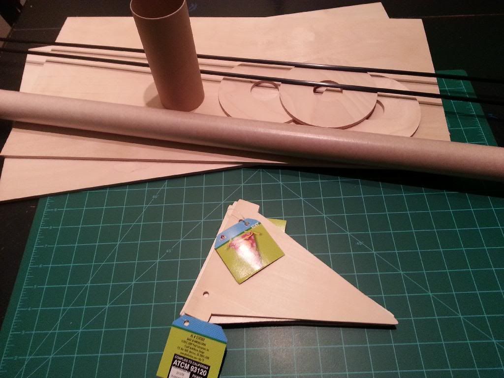
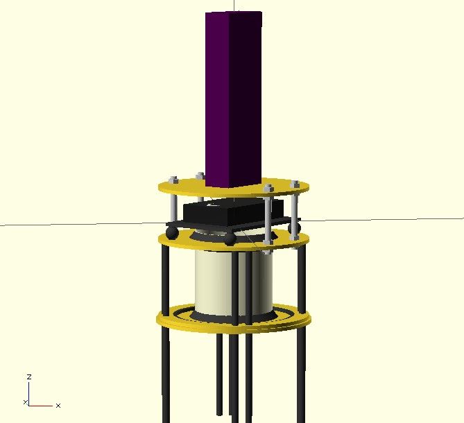
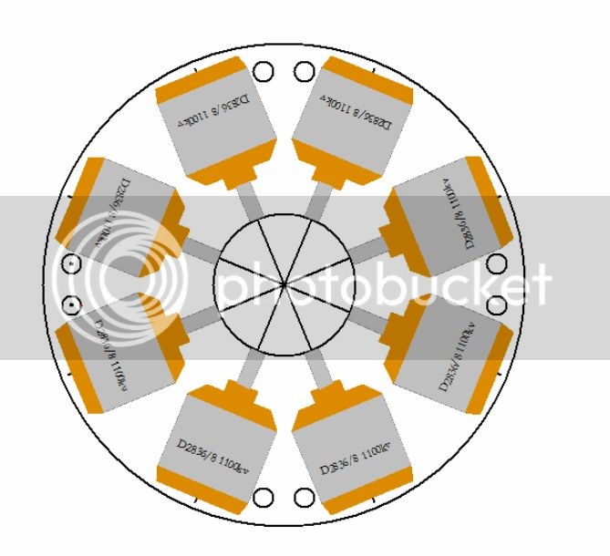
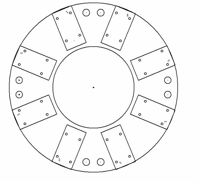
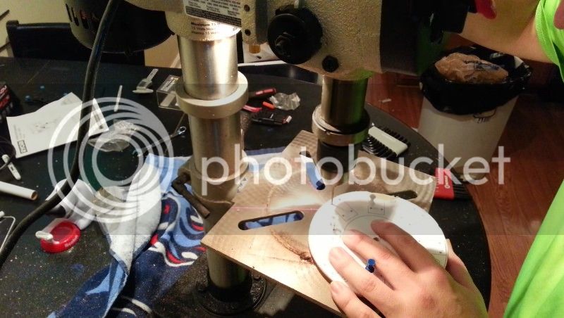
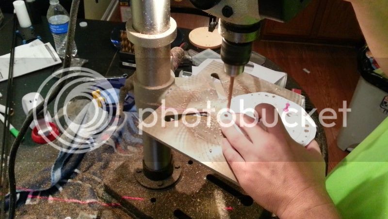
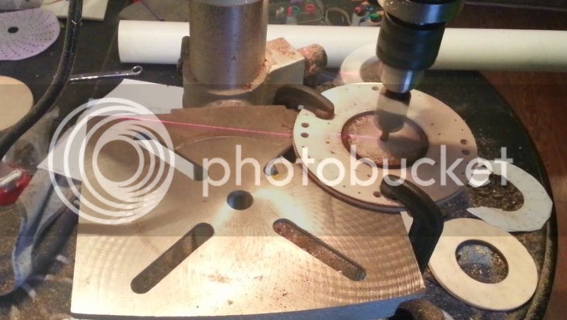
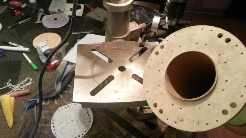
Looking at the cross section drawing of all 8 motors folded for launch, I wonder if you have figured out a way to keep props from accidentally rotating a few degrees and then the outer part of the prop blades getting hung with the vertical structural beams of the rocket? Maybe simply some little 1/64" ply fences glued to the beams, near the prop tip areas, so the prop tips could not rotate enough to get hung. I wonder about this since during the rocket boost, any yaw of the rocket at all (and all fin-stabilized rockets do yaw, it's a matter of how much) can produce an airflow vector to the side that could cause some of the props to want to rotate. Or even just vibration. So, one of those "If it can fail, it probably will" kind of things you may need to look at if you have not already addressed it.
I would be afraid to use rubber bands because of the weight if this model. That is a pretty cool rocket you have in your links there.
My main problem with doing anything smaller is the motor size. When you go smaller in motor size, the length of the motor does not really change much. Even my little 18g quad copter has motors that are a little less that half the length of these and that thing is tiny(fits in the palm of your hand). The motors that were short where really fat and gave me the same issue of fitting in a smaller body. I am already going to have to modify the shafts on the motors that I am using to make them shorter.
The only problem I see with pulling them all up with cords is I would still have to have strong hinges and the servo might have to be pretty strong to pull them all up. I was first thinking of something like that before I came across the retracts. I was thinking something like how an umbrella works though and pulling strings up through the middle.
- George Gassaway


")