Introducing 'AltiLogger', a new high accuracy altimeter

The Rocketry Forum

Help Support The Rocketry Forum:

This site may earn a commission from merchant affiliate links, including eBay, Amazon, and others.
I really would want a slightly larger one with 9-axis IMU capabilities. Deployment not necessary; I just want very accurate, reliable data logging. Add a few millimeters in length, if you don't want to sacrifice the 14mm dimension?

Adding a gyro is not just a matter if increasing board size. All gyros I found had current consumption significantly higher than you can support with such a small battery and of course the cost would also increase. I think that once I have completed this board, the next one will be a high-end one with dual deployment, higher range accel and probably gyro as well, and a LiPo battery to support the higher current needs of such a board. Keep the ideas coming!
 
It's high accuracy because I'm using a barometer that is very high resolution and is calibrated to a high accuracy by the manufacturer and also has built-in temperature compensation. On top of that the pressure-derived altitude also depends on temperature, therefore using actual temperature measurements rather than a static temperature value will give you more accurate altitude calculations. ...

A note on this:

I have been using this method on my own built altimeters for some time. While the altitude measurements are more precise, they are still off because you are measuring temperature differences inside the ebay. If you really want precision then you need to have a temperature probe outside of the rocket and shielded from sunlight.
Also, at times I had the impression of people not really trusting my altitude readouts because they were off compared to commercial altimeters.
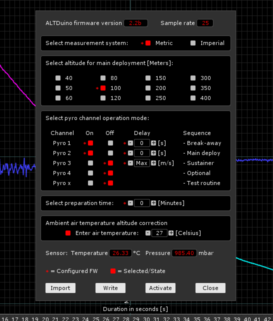
I have since made it possible via my UI software that one can choose to ignore or select "Ambient air temperature altitude correction". For most flights I elect to ignore this option simply for better mainstream comparisons :)

Temp_Comp_UI.png

I would prefer to get as accurate altitude measurements as possible, rather than getting ones that match existing ones. Have you done comparisons to GPS-based altitude measurements?
 
Heh, I wondered why no altimeter manufacturers had thought of using the ADXL375 before.

Then I looked it up and it was announced only 16 days ago.
 
Heh, I wondered why no altimeter manufacturers had thought of using the ADXL375 before.

Then I looked it up and it was announced only 16 days ago.

I was also surprised that I haven't come across it before. I've been investigating if I can fit it into my current design but it doesn't look like it will work so I'll revisit this for the next project.
 
GPS is not as accurate as baro altitude at low altitudes, and in fact you may have a difficult time getting a usable GPS altitude when moving over a few hundred ft/sec. A good high-G accelerometer with a 3-axis gyro to compensate for orientation changes with time will theoretically give you the best altitude reading, but it's not as easy as just reading a few registers in the baro chip. It's also more expensive. All of this assumes a good filter to clean up the noise, of course.

Baro sensors lose accuracy as the air thins out, that's why they are derated over 30K or 40K feet. If your goal is to make sure that the drogue chute gets out at 80,000', 100' or even 500' isn't going to make any difference. If you're going after altitude records, you're going to need to track it with GPS anyway.

I would prefer to get as accurate altitude measurements as possible, rather than getting ones that match existing ones. Have you done comparisons to GPS-based altitude measurements?
 
GPS is not as accurate as baro altitude at low altitudes, and in fact you may have a difficult time getting a usable GPS altitude when moving over a few hundred ft/sec. A good high-G accelerometer with a 3-axis gyro to compensate for orientation changes with time will theoretically give you the best altitude reading, but it's not as easy as just reading a few registers in the baro chip. It's also more expensive. All of this assumes a good filter to clean up the noise, of course.

Baro sensors lose accuracy as the air thins out, that's why they are derated over 30K or 40K feet. If your goal is to make sure that the drogue chute gets out at 80,000', 100' or even 500' isn't going to make any difference. If you're going after altitude records, you're going to need to track it with GPS anyway.

I'm not going after records, I simply want to get good and accurate data on the rocket's performance. I'm not likely to fly to such altitudes in the near future as I'm kind of new to rocketry, I'll be flying B-D motors for a while. I also want to experiment with inertial altitude determination, that's one of the reasons I have included a combination of accelerometer and magnetometer. I can determine the heading with the magnetometer quite accurately so in theory an algorithm could combine barometer and inertial data to give a more accurate altitude measurement.
 
Heh, I wondered why no altimeter manufacturers had thought of using the ADXL375 before.
Then I looked it up and it was announced only 16 days ago.

The AltimeterTwo uses the ST LIS331HH, which is 3x24g. There's a newish part, the ST H3LIS331 which is 3x200g. You may see that in some Jolly Logic versions soon.
 
The AltimeterTwo uses the ST LIS331HH, which is 3x24g. There's a newish part, the ST H3LIS331 which is 3x200g. You may see that in some Jolly Logic versions soon.

Yes I know about the LIS331HH, I've been considering using that chip together with a LIS3MDL magnetometer but I couldn't fit it on the target board size (I want this to fit into the nosecone of smaller rockets that don't have a dedicated payload area). I just saw that there's a new 1Gbit EEPROM available from RS components that is available in a small UDFN8 package which means if I use that I might be able to fit a LIS331HH and LIS3MDL on the board. The LIS331HH would work up to about 33g's when fitted at 45 degrees compared to 22g's with the current design. The board would cost about $2-3 more. I'm not too keen to do another redesign of the board but the increased accelerometer range may be worth it. Opinions?

The H3LIS331 has been available for quite some time. It can be configured to 100, 200 or 400g. If you use the 100g setting, you get 20.4 LSB per g which is about the same sensitivity as the ADXL375. However that's pretty bad resolution when you compare it to the LSM303DLHC or LIS331HH that both have 4 times that resolution (83 LSB per g).
 
Yep, higher range, less precision. Still, if someone wants something to stick it in a 70g drag race launch, that's what we're left with, right?

Interesting approach to try a magnetometer instead of a gyro for determining 3D orientation. I'm sure you're well down the path of working out the geometry involved, so maybe you could help me with one thing I've been wondering: most of the time that a magnetometer is used, an accelerometer is also consulted (presumably as the object is not accelerating much with respect to gravity) in order to figure out the orientation of "down" with respect to the lines of flux that its sensing. In other words, I imagine the lines of flux are like a thin metal axle through the magnetometer at some angle (it's a field, but imagine for the sake of explanation that it's a single axle). The magnetometer can be spun on the axle like you'd be able to spin a wheel on an axle, but it can't sense that it's being rotated, because it just knows the direction of the flux. I'm worried that this means that there is almost always at least a *component* of rotation that is lined up with the lines of flux, and that would not be sensed? To put a fine point on it, it seems to me that a magnetometer can sense two angles of orientation (the two that are othagonal to the local lines of flux), but not the axis of rotation that is parallel to the lines of flux. Am I wrong? (Not a magnetometer guru.)

At the latitude that I live (northern California) I think the local lines of flux go into the ground at an angle, and are about 15 degrees off of north. So for the least amount of error, I'd want to hope the flight arcs in a northerly or southerly direction lined up with the local compass N. If the flight arcs east or west, the "arc over" is around the lines of flux, so much of it is not sensed by the magnetometer. Does that make sense?

Yep, you can imagine the field as an imaginary line passing through your sensor. If you line up one of the axes of the sensor with this line, then you are measuring all of the field on that single axis, and the other 2 axes will read 0. If you then spin the device around that axis, you will see no change, so while you can always detect yaw and pitch, there is a special case when you won't be able to detect roll. However for an actual rocket typically flying almost vertical you will have no issues detecting roll as the field lines of the earth are never close to vertical, unless you're at the poles. Of course you will also need to take note of the 1g vector from the accelerometer just before launch which points towards the center of the earth so from that and the orientation of the field line relative to that, with a bit of vector algebra you can figure out your orientation relative to that 1g vector. That's the theory anyway. I haven't worked out all the maths yet.
 
stefel,
I think we're saying the same thing (it can't sense one direction of rotation), except that I'm thinking it's not insignificant. If you think of the lines of flux as a high bar and the magnetometer as a high-jumper that flops "over" the bar, the magnetometer can't sense the flop at all. The bar is always left to right, and the "flop" is the arc of the rocket. In reality, the lines of flux aren't horizontal (except at the equator), but that doesn't matter; the magnetometer can't sense rotation around them. If you see what I'm saying.

That's one way to visualize it, although the measured field line is always passing through the sensor, so you don't move around the line like a high jumper around a bar, it's more like the bar is passing through the middle of the jumper and you spin the jumper around that bar but I don't want you to visualize that :) However as i said this is a special case. In reality it is extremely difficult to line up the sensor close enough to the field line to completely zero out the other two axes. As you said in case of a rocket you would have to be in a very specific location on earth for the issue to arise as we can assume that the rocket will be flying not that far from vertical.
 
Regardless of whether the magnetic field lines up with any one of the axes of the magnetometer or not:

You Only Get Two Degrees of Freedom from a magnetometer. That's it. It's handy when you have rate gyros, because you can use the magnetic field to counter drift (only in those two axes!), but it cannot be relied upon alone to give you an accurate picture of the rocket's orientation.
 
It helps that at North American latitudes the inclination of the field is about 70 degrees. If you happened to be traveling exactly parallel along the lines of flux it would not matter (who cares how the rocket spins around its own long axis as we attempt to map flight arc). In every other case you will not be able to capture some component of the flight arc rotation. Sure, the worst case is traveling at a right angle to it, but every angle (except parallel) suffers to some degree. That's why I asked about whether the geometry had been studied. Any set of coordinate axes can be "projected" onto a set of coordinate axes that aligns with the flux field--then the component parallel to the direction of flux is the amount ignored. If you're traveling along the flux lines it's fine to be "blind" to that rotation axis (rocket spin), but at any other angle you're blind to some portion of arc rotation. The error is a little unpredictable, though, from flight to flight. To be safe, you'd want to always fire to magnetic N or S.
 
It helps that at North American latitudes the inclination of the field is about 70 degrees. If you happened to be traveling exactly parallel along the lines of flux it would not matter (who cares how the rocket spins around its own long axis as we attempt to map flight arc). In every other case you will not be able to capture some component of the flight arc rotation. Sure, the worst case is traveling at a right angle to it, but every angle (except parallel) suffers to some degree. That's why I asked about whether the geometry had been studied. Any set of coordinate axes can be "projected" onto a set of coordinate axes that aligns with the flux field--then the component parallel to the direction of flux is the amount ignored. If you're traveling along the flux lines it's fine to be "blind" to that rotation axis (rocket spin), but at any other angle you're blind to some portion of arc rotation. The error is a little unpredictable, though, from flight to flight. To be safe, you'd want to always fire to magnetic N or S.

In case of my design the sensor is actually sitting at a 45-degree angle relative to the rocket's body so that's also something to consider. If the rocket is sitting exactly vertical with the logger inside, then the X and Y axes are pointing 45 degrees upwards and the Z axis is parallel to the ground plane.
 
Good point about sensor fusion with gyros. Does anybody know if any of the combined IMU parts with mag and gyro do his internally?
 
In case of my design the sensor is actually sitting at a 45-degree angle relative to the rocket's body so that's also something to consider. If the rocket is sitting exactly vertical with the logger inside, then the X and Y axes are pointing 45 degrees upwards and the Z axis is parallel to the ground plane.

It doesn't matter what the sensor axes are. Even if the rocket is pointing dead vertical, a magnetometer cannot tell the difference from any rotation on that cone traced out by revolving the rocket about the magnetic field line.
 
Altimiter Three? :) Just the ticket to settle those drag-race disputes...

The AltimeterTwo uses the ST LIS331HH, which is 3x24g. There's a newish part, the ST H3LIS331 which is 3x200g. You may see that in some Jolly Logic versions soon.
 
Altimiter Three? :) Just the ticket to settle those drag-race disputes...

Well, if you want to do drag race stuff: have little holes in the sides: one with an LED and one with a photodiode. Line up the altimeters LED-to-photodiode, and it would synchronize the clocks. If you want ten of them, then you either daisy-chain them or you hold them up to the master one-at-a-time.

Then, you can know the relative liftoff times exactly and later plot the data overlaid on each other.

Just a fun feature suggestion...
 
It doesn't matter what the sensor axes are. Even if the rocket is pointing dead vertical, a magnetometer cannot tell the difference from any rotation on that cone traced out by revolving the rocket about the magnetic field line.

Yes we discussed that it won't sense if the rocket is rotating around the field line. But because field lines are not vertical, they are not parallel to a rocket's flight, so I can easily see how the rocket rolls and I can also get a good indication of the rocket's angle relative to horizontal.
 
Yes we discussed that it won't sense if the rocket is rotating around the field line. But because field lines are not vertical, they are not parallel to a rocket's flight, so I can easily see how the rocket rolls and I can also get a good indication of the rocket's angle relative to horizontal.
Absolutely correct. It's simply a 3-D compass and by orientation you can arrange the sensor to detect motion around the 3-axis. Coupled to a 3-D accelerometer you can determine orientation and a 6-DOF solution. Since 3-D gyros are cheap and readily available is really not a big deal to have a 9-DOF sensor and get accurate 6-DOF motion information. Virtually all smart phones have 9-DOF IMUs inside. The MPU-9150 is probably the first inexpensive chip that packs 3D gyros, accelerometers, magnetometers into one fused package. The datasheet and app notes give detailed information on how to use them.

Bob
 
.... Have you done comparisons to GPS-based altitude measurements?

To a certain extent until I realized the GPS data wasn't as useful as I would have preferred with the methods I was using it with.

Best thing to do is hitch a ride on a small plane and compare your measurements with the onboard instruments.
 
Yes we discussed that it won't sense if the rocket is rotating around the field line. But because field lines are not vertical, they are not parallel to a rocket's flight, so I can easily see how the rocket rolls and I can also get a good indication of the rocket's angle relative to horizontal.

I have done the math on this several years ago and I have NOT been able to show that this can be done with just a magnetometer. I found that for a given 3D mag field strength reading there are at least 2 attitudes per hemisphere.

I have not yet found any reference that what you are saying is possible is. And I have searched, and so have the DYI Drone guys. Please show me the math or reference that it is. I am anxious to be proven wrong on this because I would like a simple system like this to work. (And so would electronic compass makers would could then dispense with their accelerometers for tilt compensation).

Now if you are talking about integrating the rates of change of these fields then this may work for small rotations. Is this what you are thinking?
 
Last edited:
I have done the math on this several years ago and I have NOT been able to show that this can be done with just a magnetometer. I found that for a given 3D mag field strength reading there are at least 2 attitudes per hemisphere.

I have not yet found any reference that what you are saying is possible is. And I have searched, and so have the DYI Drone guys. Please show me the math or reference that it is. I am anxious to be proven wrong on this because I would like a simple system like this to work. (And so would electronic compass makers would could then dispense with their accelerometers for tilt compensation).

Now if you are talking about integrating the rates of change of these fields then this may work for small rotations. Is this what you are thinking?

Hi not sure what you mean by given 3D mag field strength reading. I don't care about the magnitude of the field, just the field vector, which can be normalized etc.

You need an accelerometer for a tilt-compensated e-compass because a 3D magnetometer reading will not tell you how you are oriented relative to the ground. It will simply tell you the direction (and strength) of the earth's magnetic field as it's passing through your sensor. A simple e-compass uses the X and Y axes of the magnetometer to calculate heading in degrees which works as long as the compass is held level. When the compass is tilted, you also have to include the Z axis in your calculations, but you have to know how far it's tilted, which can be determined from the accelerometer which measures a 1g force towards the center of the earth as long as you don't move it around. In my case I'm not implementing a simple compass, instead I'm looking at the field as a 3D vector and determine how the rocket is oriented relative to this vector. To determine how the rocket is oriented relative to ground (or horizontal plane) I can read both the accelerometer 3D vector and the magnetometer 3D vector just before launch (when the rocket is not yet accelerating) and then for future magnetometer readings you rotate the field vector so that it is aligned with the ground plane.

Anyway I don't want to work on this part now, I'm keen on getting boards out to people to test ASAP so right now I want focus on getting the V2 hardware prototyped and tested and I still need to get firmware update over USB implemented so that I can provide fixes and improvements to people after they have the boards. I have made the decision to produce the V2 with the current spec and not do another re-design as it's impossible to make one board to satisfy all needs, I will probably make a high end board later as I'll be wanting to get into higher power rocketry eventually.
 
First off the pad is easy, of course. First to altitude is tougher, you either need to do it after the fact with the data from the flight computer, or you need to use a big tape like runners have in marathons, at about 2500' or so, and the first rocket to break it wins.

Drag races are the beer pong of the rocketry world. :)

?

I meant for "first-off-the-pad" or "first-to-altitude" contests.
 
Hi,

As has been stated, inertial navigation in the general case is impossible with just an accelerometer and magnetometer. You only get 5 degrees of freedom from those, and you need six. Specifically, if the rocket arcs so that it rotates around the magnetic lines, there's no way to detect it. You need something else as well.

Using the physics of a rocket might help. By assuming that the rocket flies with an average angle of attack of zero, you might be able to determine the direction of gravity. If the accelerometer displays acceleration that is not longitudal with the rocket for some time, this indicates that the rocket is not flying straigt up, and you can get an indication of the angle from the direction the the acceleration. (This assumption breaks down if the rocket is heavily asymmetric.)

Another place for an additional DOF is the baro-altitude. In theory, knowing the altitude would add the necessary DOF. If the altitude does not increase at the velocity the rocket is moving (based on the accelerometer), then you're flying at an angle. You don't know whether you're arcing left or right, but otherwise it should be unique. The problem is that during flight the baro altitude might not be completely accurate, due to pressure gradients at the venting holes (especially in supersonic flights).

By building a physics model and a Kalman filter around it, you might be able to get pretty good results. Though it may get very error-prone if the rocket is rolling fast.

Cheers,
Sampo N.
 
Back
Top