MOSFET pyro charge ignition and continuity

The Rocketry Forum

Help Support The Rocketry Forum:

This site may earn a commission from merchant affiliate links, including eBay, Amazon, and others.

zortness

Active Member
Joined
Jun 21, 2013
Messages
36
Reaction score
0
I'm not an EE, so I'm learning this as I go, with the help of some people here on the forum (like awseiger) and some friends of mine who are EEs.

Wondering if anyone has any feedback on this initial design for controlling a pyro charge ignition via N-Channel MOSFET, and also reading continuity. I currently control the pyros in my prototypes with solid state relays, but MOSFETs seem like a more standard, smaller footprint, and much cheaper choice.

In the diagram, just assume the 3.3V system is regulated, but logic input/output is on those levels.


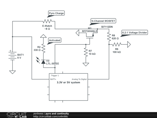
I've noticed some examples where people tie the continuity reading directly into an MCU, but I'm not particularly comfortable with that. I also want to be able to support voltages between 6V and 20V. I also want to be able to support a wide variety of ignition sources with varying resistances.

Feedback appreciated, thanks everyone! I'll keep the diagram updated.
 
It's interesting that you used a voltage divider directly into the controller... I guess this means you input voltage has to be between 6V and 9V, which probably isn't an unreasonable expectation. I guess the abstraction that I wanted to solve is to be able to support the Arduino Due (3.3V) and the Mega (5V).
 
Just a note, the MOSFET in my original diagram actually had the source and drain reversed. I fixed it (the diagram visible in the thread is up to date).
 
Most flight controllers will work with an e-match w/o buffering. Why are you adding this level of complexity? So far the only reason I have found is to drive full on igniters for staging,

Just curious.
 
A few things you might want to look at...

1) You may not need R4 if you're only using ematches, but if you want to use it to protect your FET from overcurrent, 1-2 ohms should be fine (you'll need at least a 5W resistor, however). An alkaline 9v will dead-short at nearly 5A, so if your ematch is 1 ohm then a 1 ohm R4 will net you 2 ohms, or about 4A at 9v; that should be above the all-fire current of just about any ematch.

2) I assume the "3.3v system" puts out CMOS 3.3v level outputs, and wants to see no more than 3.3v in. I don't know why you have the CD4050 buffer, the output is going to be 9v which will fry your MCU. You can put a 3:1 voltage divider between the igniter and your input, if the igniter is open then it will sink to ground, if 9v is present you'll see about 3v on the input which will be just fine.

3) R7 is way too big, cut it down to about 10K or even less. Any MCU worth a dang is going to source at least 5-10 ma, the more sink to ground you have on your FET's gate, the better EMI immunity you're going to get, and your MCU will have no trouble driving it.

4) R2 could be higher, 330 ohms is going to require almost 10 ma to drive it. I'd make it at least 1K. A high-brightness LED will work fine with 2-3 ma.

Good luck with your project!
 
1) You may not need R4 if you're only using ematches, but if you want to use it to protect your FET from overcurrent, 1-2 ohms should be fine (you'll need at least a 5W resistor, however). An alkaline 9v will dead-short at nearly 5A, so if your ematch is 1 ohm then a 1 ohm R4 will net you 2 ohms, or about 4A at 9v; that should be above the all-fire current of just about any ematch.

It is worse than that because the resistor is between source and ground. So as Id increases so does the voltage at the source. Since the voltage at the gate is fixed, the gate to source decreases. The end result is that you might not get 2A into a short circuit if R4 was 1 Ohm.
 
Thanks for the feedback! H_Rocket, I think the answer to your question/comment is also included below.

1) You may not need R4 if you're only using ematches, but if you want to use it to protect your FET from overcurrent, 1-2 ohms should be fine (you'll need at least a 5W resistor, however). An alkaline 9v will dead-short at nearly 5A, so if your ematch is 1 ohm then a 1 ohm R4 will net you 2 ohms, or about 4A at 9v; that should be above the all-fire current of just about any ematch.

I want to be able to support 6 to ~15V input. Right now, my battery connector is only rated up to 1A (a JST through-hole receiver)... So I would either have to change that out, or limit the current to around 1A.

2) I assume the "3.3v system" puts out CMOS 3.3v level outputs, and wants to see no more than 3.3v in. I don't know why you have the CD4050 buffer, the output is going to be 9v which will fry your MCU. You can put a 3:1 voltage divider between the igniter and your input, if the igniter is open then it will sink to ground, if 9v is present you'll see about 3v on the input which will be just fine.

It's actually a bit more complicated than that. I want to support the voltage ranges above. Also, I want to support the 5V logic Arduino Mega, as well as the 3.3V logic Arduino Due (and others). The CD4050 flips to high at anything from 1V to 20V and then outputs at whatever the IOREF voltage is, which seems to be a good deal. The resistor is actually there to cut the current flow down to nearly zero and keep the pyro charge from igniting. That said, I'm still teaching myself all of this stuff, which is why my understanding and/or math might be completely off =P

3) R7 is way too big, cut it down to about 10K or even less. Any MCU worth a dang is going to source at least 5-10 ma, the more sink to ground you have on your FET's gate, the better EMI immunity you're going to get, and your MCU will have no trouble driving it.

That value was a suggestion from another member, but it's easily adjusted.

4) R2 could be higher, 330 ohms is going to require almost 10 ma to drive it. I'd make it at least 1K. A high-brightness LED will work fine with 2-3 ma.

Fixed.

Good luck with your project!

Thanks! Appreciate the help.
 
You also might want to think about using optoisolators to connect your Arduino and the peripheral circuitry. That way, it doesn't matter what voltage you use on either end as long as you don't get too crazy, and you use decent current-limiting resistors between your source and the emitter. (Usually 2.2K - 10K, depending on the input voltage; you want the current to be under 5 ma but you can go under 1 ma and it will work fine. The voltage drop on a typical optoisolator emitter is about 1.3v or so).
 
You also might want to think about using optoisolators to connect your Arduino and the peripheral circuitry. That way, it doesn't matter what voltage you use on either end as long as you don't get too crazy, and you use decent current-limiting resistors between your source and the emitter. (Usually 2.2K - 10K, depending on the input voltage; you want the current to be under 5 ma but you can go under 1 ma and it will work fine. The voltage drop on a typical optoisolator emitter is about 1.3v or so).

Interesting, I'll look into the optoisolators.

I actually have this circuit wired up and functional at the moment, testing with a variety of resistor values, etc. It works from 6-12V with the CD4050 and the HC4050 hex converters. I'll try out some higher voltages tomorrow. R4 is currently 330 and R6 is 660k.

Also testing out a P-Channel MOSFET for reverse voltage protection rather than a diode... seems to work so far.
 
I'm not as experienced as some of the guys here with electronics, but wouldn't it make sense to keep the igniter at ground by default instead of Vdd? Far harder to accidentally short the igniter that way, I would imagine.
 
I'm not as experienced as some of the guys here with electronics, but wouldn't it make sense to keep the igniter at ground by default instead of Vdd? Far harder to accidentally short the igniter that way, I would imagine.

That's actually a function of the way the N-Channel mosfets work, they need to be between the load and ground. If you look at other altimeters, most of them are probably wired up in a similar fashion (such as the Raven).
 
The Eggtimer has the igniters on the ground side, but it uses BJT transistors in a common-collector configuration, not FETs.

That's actually a function of the way the N-Channel mosfets work, they need to be between the load and ground. If you look at other altimeters, most of them are probably wired up in a similar fashion (such as the Raven).
 
If you power the igniters with the arm/power switch, you can check continuity by drawing somewhere between 1 ua to 1 ma through the igniter, and when you want to fire it, you simply use the low resistance FET to complete the circuit. The advantage is also that it allows for a different igniter battery voltage than the computer uses as you are simply supplying a return path for the current with the FET at near ground (return potential) since the voltage drop is across the igniter.
 
What's the advantage over a Schottky diode? Edit: Ok I watched the video.
 
Last edited:
A few things you might want to look at...

1) You may not need R4 if you're only using ematches, but if you want to use it to protect your FET from overcurrent, 1-2 ohms should be fine (you'll need at least a 5W resistor, however). An alkaline 9v will dead-short at nearly 5A, so if your ematch is 1 ohm then a 1 ohm R4 will net you 2 ohms, or about 4A at 9v; that should be above the all-fire current of just about any ematch.

It would be smaller and probably less expensive to skip the 5 Watt current-limiting resistor (they're huge) and just use a MOSFET that can handle any battery current you can throw at it. (20+ Amps) That will also deliver more power to your ematch for any battery. The downside is that you have to maintain power to the microcontroller in the event of a short.

2) I assume the "3.3v system" puts out CMOS 3.3v level outputs, and wants to see no more than 3.3v in. I don't know why you have the CD4050 buffer, the output is going to be 9v which will fry your MCU. You can put a 3:1 voltage divider between the igniter and your input, if the igniter is open then it will sink to ground, if 9v is present you'll see about 3v on the input which will be just fine.
+1 on dividing the voltage down. But I would divide it down maybe 6:1 and put it into the microcontroller's A/D converter so that you can detect continuity from a wider range, say 1V to 20V. You can also skip the buffer part that way.
 
You're right on both points. As far as the current-limiting goes, if all you are going to do is fire ematches, any FET that can handle 2A continuous would work fine, and you can get a smaller and cheaper part. At some point, cost comes into play... I would imagine that using a
1N400x diode for reverse-voltage protection is going to be much less expensive than a P-FET.
 
Back
Top