You are using an out of date browser. It may not display this or other websites correctly.
You should upgrade or use an alternative browser.
You should upgrade or use an alternative browser.
Fly Straight Up
- Thread starter Joe Walsh
- Start date


Help Support The Rocketry Forum:
This site may earn a commission from merchant affiliate
links, including eBay, Amazon, and others.
Neither one will work if your rocket has more than a 16 G acceleration unless you add an accelerometer with a lower sensitivity.
for simple stabilization you do not need the accelerometers, just the gyros.
This isn't quite right: you need the accelerometers, but it's okay if you accelerate faster than 16G. These MEMS gyros drift badly, so the accelerometer is used to correct them on the pad. Once the rocket is airborne under thrust, the accelerometer is "lying" about which way is down (mostly just points out the back of the rocket) and isn't used. It won't matter if the acceleration exceeds 16G. The gyros will thus begin to accumulate drift on the order of ~10°/minute. This is probably negligible for rocketry purposes.
You guys think this configuration/coding has a future or is worth working on?
Your plan for the GY-80 is fine. If vshymanskyy's code doesn't work, try Jeff Rowberg's: https://www.i2cdevlib.com/devices. He has code for each of the chips on the GY-80 board except the BMP085, which is currently in progress.
DaveHein
Well-Known Member
- Joined
- Feb 19, 2009
- Messages
- 619
- Reaction score
- 17
If the intent is to fly straight up, an accelerometer is not needed as long as the rocket is pointing straight up at launch. If the rocket is not exactly vertical at launch an accelerometer can be used to determine at launch time how much the rocket is tilted, and it can be steered into vertical based on the gyros.
So an accelerometer is not needed to maintain vertical flight. However, an accelerometer can be used to determine your position in 3D space, and you can log that information or you could even use it to maintain the rocket directly over the launch pad during it's flight. If there is a cross-wind the rocket will drift down-wind even if it points straight up during the flight. An accelerometer could be used to compensate for the drift due to wind.
So an accelerometer is not needed to maintain vertical flight. However, an accelerometer can be used to determine your position in 3D space, and you can log that information or you could even use it to maintain the rocket directly over the launch pad during it's flight. If there is a cross-wind the rocket will drift down-wind even if it points straight up during the flight. An accelerometer could be used to compensate for the drift due to wind.
So, during the propelled phase the accelerometer goes bananas (at least the axis on which the thrust is applied,right?)
In the gy80, for example, we still have the pressure sensor and the magnetometer...can't we make use of them to suppress the lack of a working accel?
In the gy80, for example, we still have the pressure sensor and the magnetometer...can't we make use of them to suppress the lack of a working accel?
- Joined
- Jan 23, 2009
- Messages
- 5,981
- Reaction score
- 4,091
This isn't quite right: you need the accelerometers, but it's okay if you accelerate faster than 16G. These MEMS gyros drift badly, so the accelerometer is used to correct them on the pad.
You do not need to correct the gyros at the pad with accelerometers. You simply record the gyro reading at launch, subtract the launch reading from subsequent readings and integrate.
- Joined
- Jan 23, 2009
- Messages
- 5,981
- Reaction score
- 4,091
So, during the propelled phase the accelerometer goes bananas (at least the axis on which the thrust is applied,right?)
In the gy80, for example, we still have the pressure sensor and the magnetometer...can't we make use of them to suppress the lack of a working accel?
Theoretically the 3axis magentometer can provide a 3D reference vector to compensate for gyro drift. I just haven't seen alot of success with this approach in the DIYDrone community.
Even 2D yaw magnetometer correction is less prefered than gps correction.
DaveHein
Well-Known Member
- Joined
- Feb 19, 2009
- Messages
- 619
- Reaction score
- 17
No, the accelerometer doesn't go bananas during the propelled phase. It just measures the acceleration on the local inertial reference. If you integrate the output from the accelerometer (minus the earth's acceleration) you'll get your velocity. If you integrate the velocity you'll get your location relative to your starting point on the surface of the earth. The tricky part is doing this in three dimensions. The accelerometer must also be compensated for any DC offsets, or the velocity will drift, and the location will be wrong. The DC offsets can be determined during the time the rocket is sitting on the pad.So, during the propelled phase the accelerometer goes bananas (at least the axis on which the thrust is applied,right?)
In the gy80, for example, we still have the pressure sensor and the magnetometer...can't we make use of them to suppress the lack of a working accel?
Note that the accelerometer tells you the velocity and location of the rocket, but it doesn't tell you which way the rocket is pointed. That's what the gyro does. The direction that the rocket is pointed is important for interpreting the information from the accelerometer. If the rocket is initially pointed straight up, then the XYZ coordinates of the rocket, and the accelerometer are aligned with the XYZ of the local space reference. However, if the rocket is tilted with respect to the local coordinates then the output from the accelerometer must be rotated in 3D space to match the inertial frame.
Last edited:
I see. I'm going to simulate the rocket dynamics in simulink using 6dof to come up with the controller gains to be used in the kalman filter...
Silly question: why wouldn't those gy80 ahrs (attitude and heading reference system) ready codes work for our purposes? It outputs all Euler angles, right? (Or even quaternions if desired).
Using the given Euler angles we have the attitude of the rocket in respect to the earth. Then we could integrate and use the sensors data to come up with the actual position.
Or am I going in a completely wrong direction here?
- Joined
- Jan 23, 2009
- Messages
- 5,981
- Reaction score
- 4,091
I see. I'm going to simulate the rocket dynamics in simulink using 6dof to come up with the controller gains to be used in the kalman filter...
Silly question: why wouldn't those gy80 ahrs (attitude and heading reference system) ready codes work for our purposes? It outputs all Euler angles, right? (Or even quaternions if desired).
Using the given Euler angles we have the attitude of the rocket in respect to the earth. Then we could integrate and use the sensors data to come up with the actual position.
Or am I going in a completely wrong direction here?
If the ready code was purposed for drones which are primarily horizontal flying machines with an average z acceleration of 0, use in a rocket application will lead to errors because that code uses the z-accelerometer to provide a reference gravity vector to compensate for gyro drift. In a rocket flight there isn't a gravity reference vector available.
If you can set defines in the code to disable specific gyro compensation methods then you may get it to work for you.
The more I read, the more I think I hit a dead end even before starting! Hahahaha
So how is it done then? I mean, specifically for the rocket case... Airplanes and quads seem kids stuff for me after reading the issues of the rocket....
So how is it done then? I mean, specifically for the rocket case... Airplanes and quads seem kids stuff for me after reading the issues of the rocket....
- Joined
- Jan 23, 2009
- Messages
- 5,981
- Reaction score
- 4,091
The more I read, the more I think I hit a dead end even before starting! Hahahaha
So how is it done then? I mean, specifically for the rocket case... Airplanes and quads seem kids stuff for me after reading the issues of the rocket....
Depends what you are trying to do. If you just want to stabilize the rotation of the rocket you can depend on gyro's alone because the boost duration is short enough to tolerate gyro drift.
If you want an accurate IMU generated navigational fix for a relatively long flight (>60secs) you need an IMU with REALLY GOOD $$$$ gyro's that do not need drift compensation. A decent compromise would be a "hobby grade" IMU to determine the fix during boost and then switch to GPS during the coast and perhaps use the GPS data to drift correct the gyros.
UhClem
Well-Known Member
- Joined
- Feb 6, 2009
- Messages
- 2,052
- Reaction score
- 443
So how is it done then? I mean, specifically for the rocket case....
I would point you at NASA Technical Memorandum 4775 "Development of a Closed-Loop Strap Down Attitude System for an Ultrahigh Altitude Flight Experiment" but that web page seems to be down.
vshymanskyy's code has a drift correction using the magnetometer...should it be disabled then for rocketry purposes? How could I test if this correction works?
Either way, I guess I can then use the gyro neglecting the drift since my rockets only burn for 3 or 4 seconds... This way, can I use the gyro for attitude and accelerometer for velocity and position without any fear?
I didn't know there were gyros without drift...will read about them just out of curiosity.
About GPS, the most common are 10 and 5Hz...is it fast enough for usage in flight calculations? How would it be added to a kalman filter for sensor fusion?
I'll definitely take a look at that NASA paper as soon as things get back to normal in the website.
- Joined
- Jan 23, 2009
- Messages
- 5,981
- Reaction score
- 4,091
The ST gyro I have been developing a board with has drifts less than a degree in 20 seconds. That is static on the bench and I have done some 90 degree rotations in 3 axes and back to zero in that time with very little drift. In a flight subjected to acceleration may be another story thought and I have tested that mode yet.
Vshymanskyy's magnetometer drift correction may be just 2 axis only on the horizontal component of the magnetic field. If it is, then its not terribly useful for a rocket.
There should also be code in there for GPS flight correction. If not see code for the ArduIMU board. Similar idea.
Vshymanskyy's magnetometer drift correction may be just 2 axis only on the horizontal component of the magnetic field. If it is, then its not terribly useful for a rocket.
There should also be code in there for GPS flight correction. If not see code for the ArduIMU board. Similar idea.
Area66
Well-Known Member
- Joined
- Apr 5, 2013
- Messages
- 2,251
- Reaction score
- 4
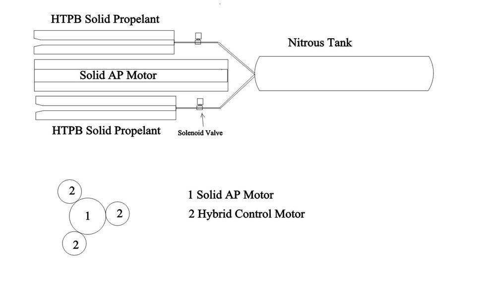
Here my idea to stabilise a rocket, I want to use 3 hybrid motor with the injection of Nitrous controlled by the flight computer, be reducing the flow on select motor and pushing more on the other one we can stabilise the rocket.
Last edited:
DaveHein
Well-Known Member
- Joined
- Feb 19, 2009
- Messages
- 619
- Reaction score
- 17
It would work in theory, but it might be hard to build a practical system. One problem is that the lever arm that the steering rockets are pushing on is shorter than the level arm with a gimballed motor. With a gimballed motor, the length of the lever arm is the distance from the nozzle to the Cg as measured along the length of the rocket. With your system, the lever arm is the distance measure along the width of the rocket. I think your hybrid motors would need to have about the same thrust as your solid motor, and you would need to be able to reduce the thrust to almost zero. Also, your variable thrust would need to go from minimum to maximum very quickly -- on the order of one-tenth second.
What do you guys think about installing the gyros/sensors in a temperature controlled environment? Shouldn't be hard to do and shouldn't require too much energy if designed properly (as small as possible with good insulation material). With that and a good start-up calibration routine the drift should be greatly decreased, right?
What do you guys think about installing the gyros/sensors in a temperature controlled environment?
I think making a temperature controlled environment is going too far. My project used the MPU-6050 from Ivensense. It comes with a temperature sensor onboard, which is used to adjust the gyro readings before they are sent to the buffer. A good breakout board for the MPU-6050 is the GY-521.
DaveHein
Well-Known Member
- Joined
- Feb 19, 2009
- Messages
- 619
- Reaction score
- 17
The motor burns are so short that it seems that temperature control is not needed. The sensor offsets can be measured just before launch, and used during the motor burn. I don't think they would change much during the few seconds that the motor is burning.
Now if the rocket is actively controlled during the entire ascent there will be a little bit of drift, but it still seems like the temperature won't change much during the entire ascent unless you are going for very high altitude.
Gérard, your variable-thrust hybrid looks interesting. Has anybody ever built and flown something like this?
Actually I already have an ArduPilot 2.5, which uses the MPU-6000.
Do you guys know if it is possible to use this platform to actuate servos? (I mean, use the board/hardware only....I know the firmware it has on it is useless for us).
I~m asking because it has the I/O pins, the processor and sensors in the board already!
Do you guys know if it is possible to use this platform to actuate servos? (I mean, use the board/hardware only....I know the firmware it has on it is useless for us).
I~m asking because it has the I/O pins, the processor and sensors in the board already!
- Joined
- Jan 23, 2009
- Messages
- 5,981
- Reaction score
- 4,091
The ArduPilot can be useful for a rocket. You can disable the gyro corrections in the firmware.
The body coordinate system is represented in a DCM matrix. If you simply take the vector cross product of this DCM with the earth z-axis you then get correction magnitudes for the body x and y axes. You will then just have to write your servo routines (if memory is available) and you will be all set.
The body coordinate system is represented in a DCM matrix. If you simply take the vector cross product of this DCM with the earth z-axis you then get correction magnitudes for the body x and y axes. You will then just have to write your servo routines (if memory is available) and you will be all set.
Nice, so my ardupilot is flying a rocket!
Anybody has experience on writing custom codes for ardupilot board?
Or should I just connect it to a second arduino? (I guess it would compromise the speed of the actuating system...)
Anybody has experience on writing custom codes for ardupilot board?
Or should I just connect it to a second arduino? (I guess it would compromise the speed of the actuating system...)
Last edited:
No problem!
Well, I guess I could connect the ardupilot to an arduino and add a GPS and make all communicate and etc....or even buy a cheap GY80/GY521 and build a nice board to secure them and add some parachute deployment hardware and so on.... but that would require a lot of coding, tweaking, hacks and testing....so I think it is better just to use the right tool for the task:
https://github.com/zortness/rocket-mega-shield
It has everything an amateur rocketeer could possible need with solid coding and everything just sitting on a nice board over an arduino.
Depolyment, logging and telemetry routines are pretty much done and still enough room to add control and stability routines, which should be easy because sensor reading and filtering codes are ready to use. A very good deal for its price: USD113.00 (ready to use!)
CarVac
Well-Known Member
- Joined
- Feb 12, 2012
- Messages
- 5,704
- Reaction score
- 37
Bottle rockets fly straight up (mostly) and don't have any fins.
Bottle rockets have that long stick which act as fins: it has a bigger effect on the CP than on the CG.
Larry Curcio
Well-Known Member
- Joined
- Mar 5, 2009
- Messages
- 538
- Reaction score
- 3
I'm surprised no one mentioned Alyssa Stenberg's NARAM 55 R&D report. It's the most remarkable project I've ever seen - and in A Division no less! Sorry I wasn't there!
https://www.youtube.com/watch?v=A4M9Uso9EsY
Congratulations, Alyssa!
-Larry Curcio
https://www.youtube.com/watch?v=A4M9Uso9EsY
Congratulations, Alyssa!
-Larry Curcio
Similar threads
- Replies
- 38
- Views
- 2K
- Replies
- 106
- Views
- 6K
- Replies
- 31
- Views
- 1K
- Replies
- 16
- Views
- 609
- Replies
- 4
- Views
- 564