Wireless Launch Control System V2

The Rocketry Forum

Help Support The Rocketry Forum:

This site may earn a commission from merchant affiliate links, including eBay, Amazon, and others.

jus_rockets

Well-Known Member
Joined
Jan 9, 2012
Messages
1,218
Reaction score
12
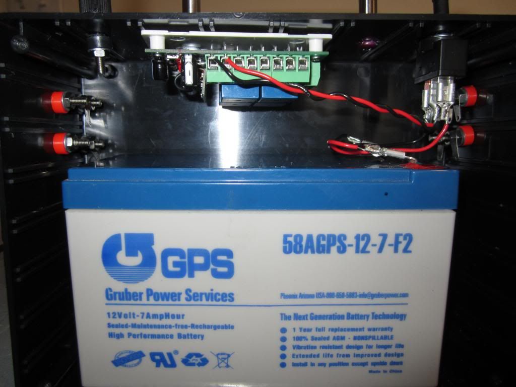
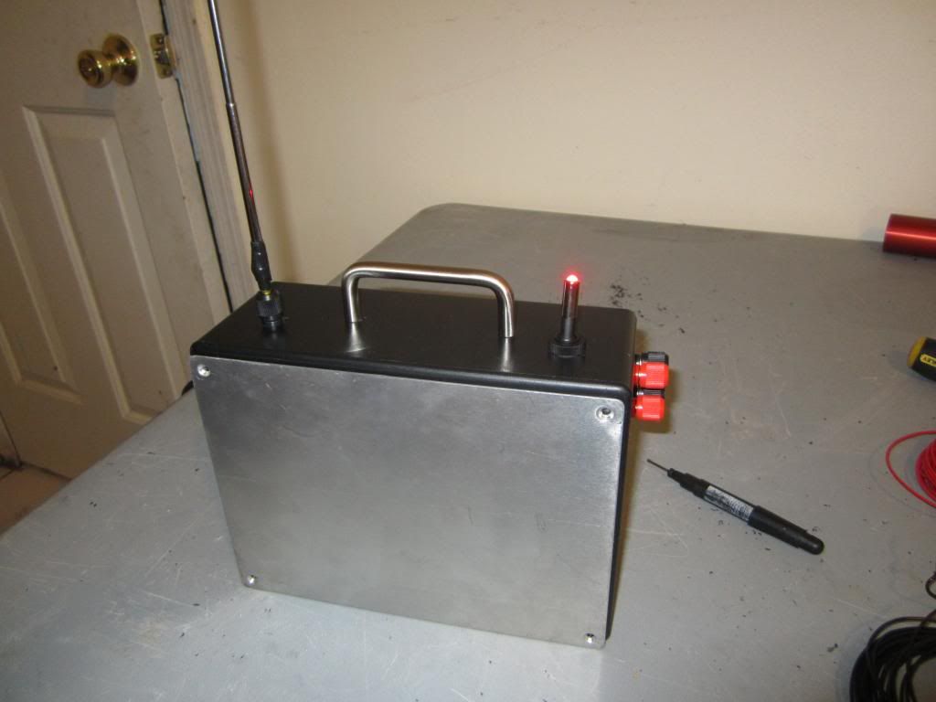
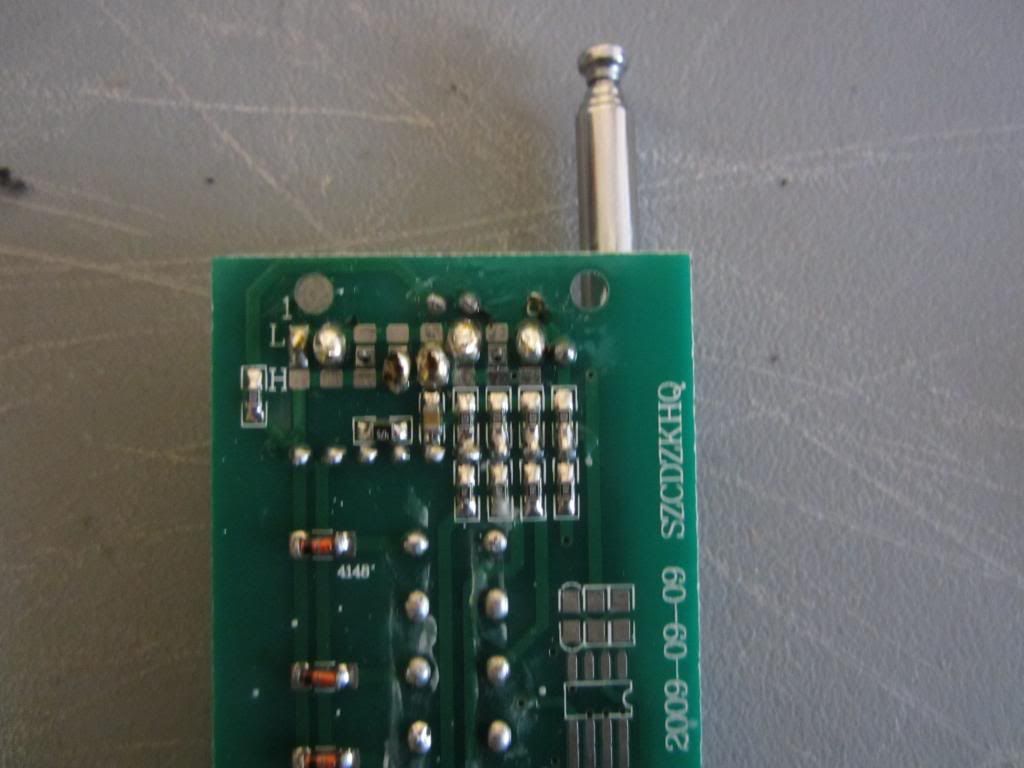
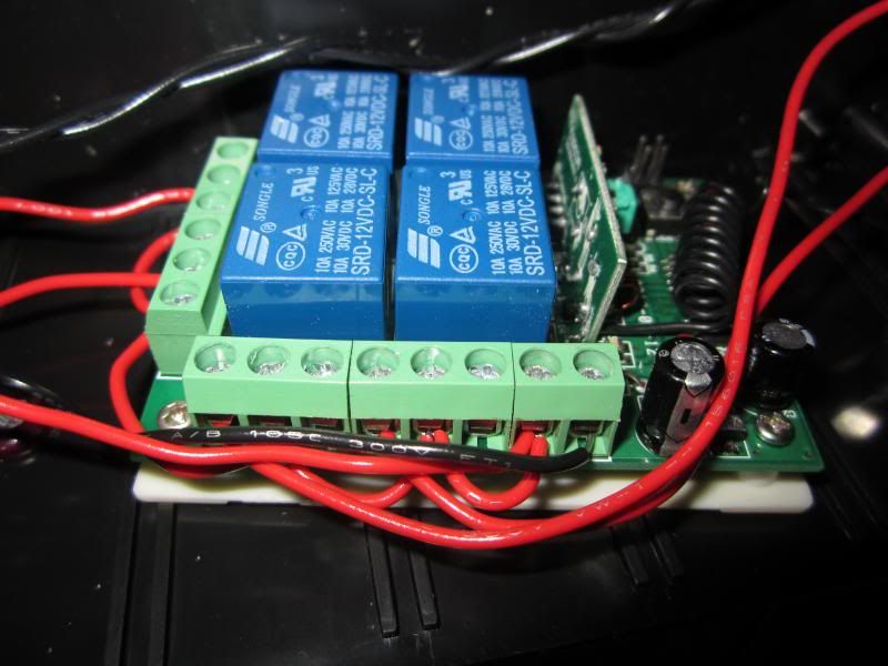
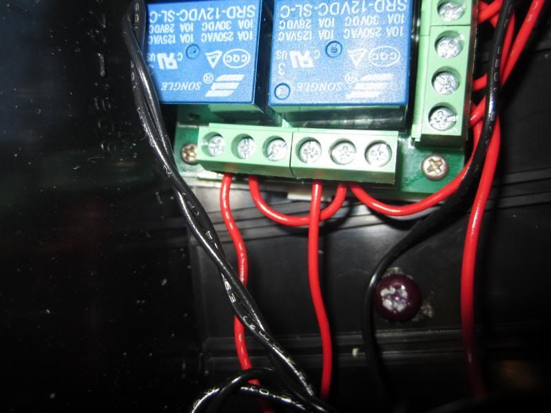
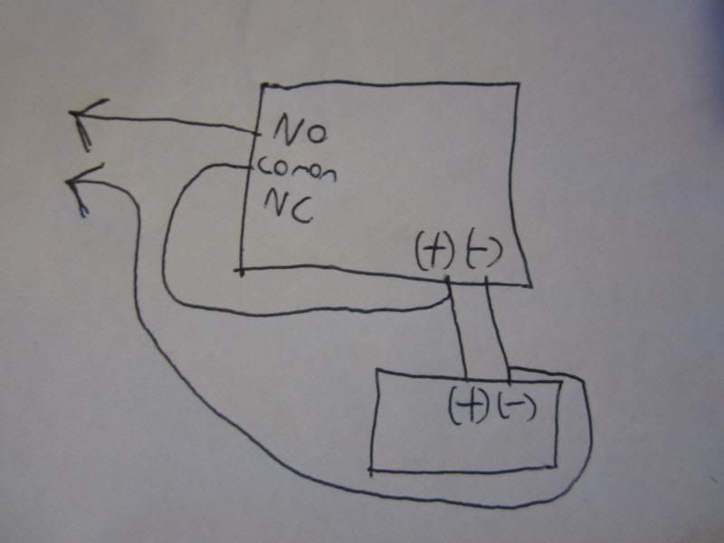
Well my previous controller I made has worked great, but I wanted to make a safer and longer range system. So I ordered a tx/rx that is theoretically rated to 3000m range , I will be happy getting 1000ft range. This will be a 4 pad system using the relays on the receiver. If your planning on using a 315/433 mhz tx/rx on a fix 8-bit code make sure you solder your custom code. Another thing different is the transmitter has an on/off switch which makes it much safer, I am also planning of adding a removal key of some sort. I should have this done and tested by the weekend.

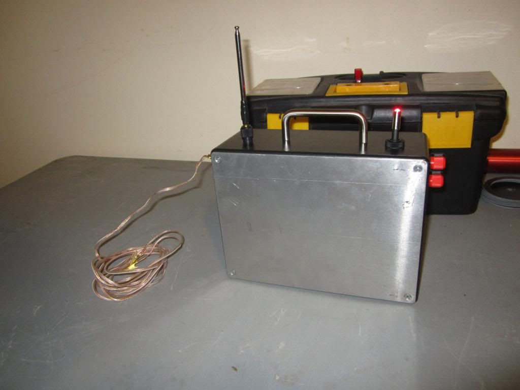
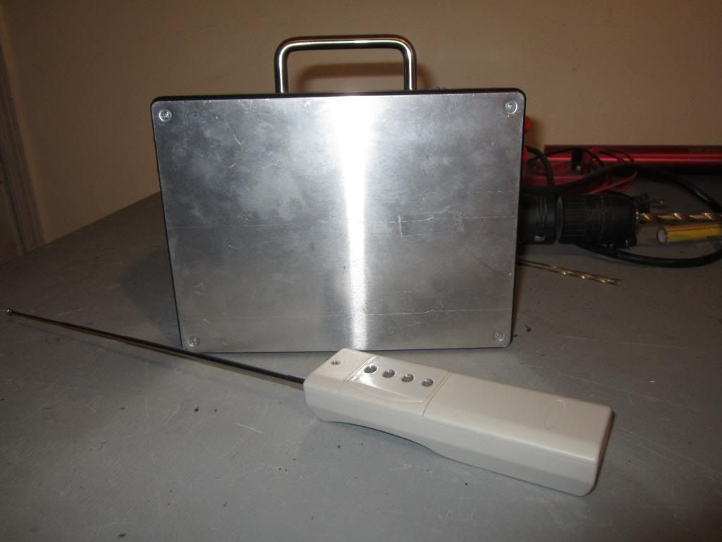
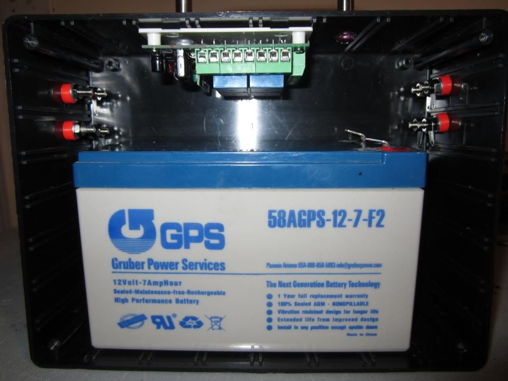
8X6X3 project enclosure from Radioshack, handle is from a drawer
IMG_1319_zps083cd3ca.jpg


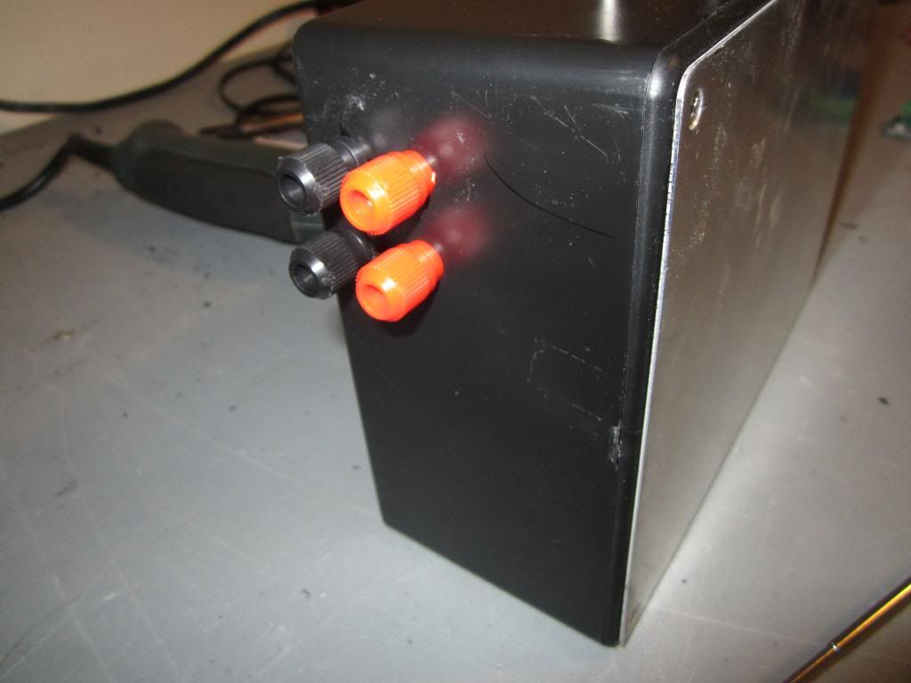
Binding post on both sides
IMG_1320_zps819c081f.jpg

IMG_1321_zps7128f6c9.jpg


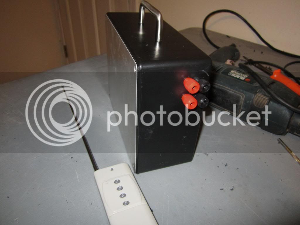
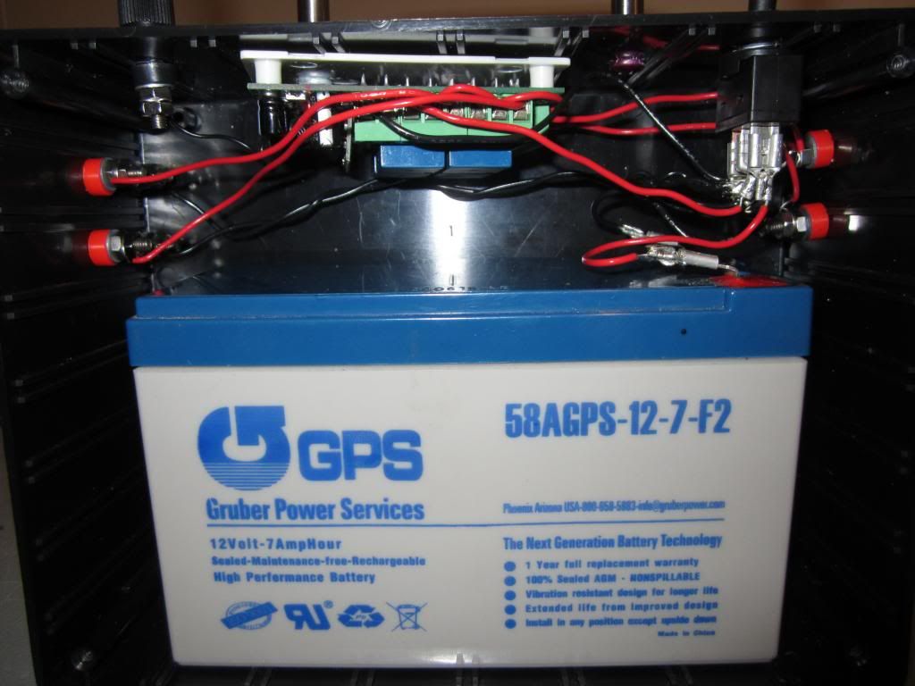
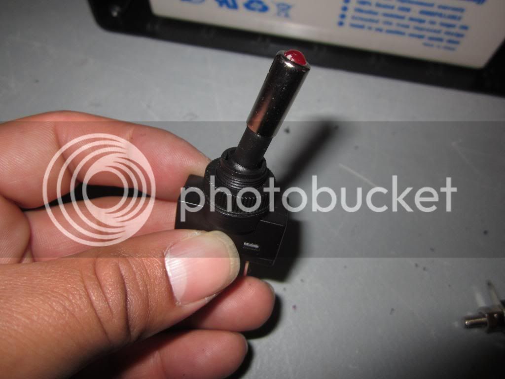
LED on/off toggle switch that will turn on receiver
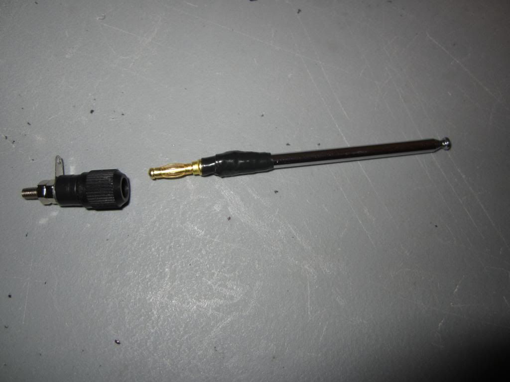
IMG_1325_zps33861299.jpg


Removable antenna
IMG_1324_zpse94bee0c.jpg


This should be fun to wire!
IMG_1323_zps6106350c.jpg
 
Looking good . I finally got tracking number for the receiver and transmitter I ordered. They look a lot alike. The only difference I can see is mine comes with a prewired external antenna.
 
Brent,

I think we can make one heck of a nice looking system with this device. To get the full range, you will need to mount the receiver on a ladder or tripod.
 
Brent,

I think we can make one heck of a nice looking system with this device. To get the full range, you will need to mount the receiver on a ladder or tripod.

I have an old cymbal stand that will work for that.
 
Looks great!!
Were you able to figure out how to get each relay to come on only while the button is held down (Momentary)?
It seems on mine, two of the relays act differently from the other two, no matter how I have the jumpers set.
I may just wire a NO switch in as the 'ARM' switch, then try to run them individually. Right now, I have to
hold down the 'C' button, and then hit 'D' to fire. Was unable to get 'A' and 'D' to work together like that.

R

They should all be momentary with both jumpers off, that how mine is set. I was going to try pressing two buttons to launch but since I have an on/off switch on the transmitter that will be my safety switch. Maybe you have a faulty receiver board, all relays should be momentary with the jumpers off.


Here is my 8-bit address 11022101. My receiver is a learning type which will learn any code, if you have a fixed type solder on the same address on the receiver.

IMG_1335_zps95b6e264.jpg

003_zpse687c956.gif
 
Last edited:
Yep, you were spot on. Just played with it this morning when I got up. Pulled both jumpers, worked perfectly. Set a custom code, so all I need now is
a box and some connectors. I'm going to borrow the switch with cover from my daughters race car (I haven't installed it yet, I'll get her another!)

Ron
 
12 volt  for 4 pads.jpg

Jus_rockets helped me with mine and this was my final wire diagram... Works great... with it on the ground I get 500 feet, so on a tripod I'd hope to get more... BTW love the box, my tool box is just lame IMHO
 
That's awesome to hear you get 500ft on the ground!! I've got a couple of tripods laying around. I'm going to put a mount on whatever box I make and stick it up in
the air a few feet, just for good measure!

R
 
Yep, you were spot on. Just played with it this morning when I got up. Pulled both jumpers, worked perfectly. Set a custom code, so all I need now is
a box and some connectors. I'm going to borrow the switch with cover from my daughters race car (I haven't installed it yet, I'll get her another!)

Ron

Hopefully she wont notice and get mad lol! What kind of enclosure your going with?

View attachment 115114

Jus_rockets helped me with mine and this was my final wire diagram... Works great... with it on the ground I get 500 feet, so on a tripod I'd hope to get more... BTW love the box, my tool box is just lame IMHO

I think the tool box is cool but the enclosure does look more profesional
 
Last edited:
Well, I got the wireless module wired into my existing launch controller. It's ugly (Original one) but both wired and wireless work as they should!
I really think I'm going to make an attempt at building as small and lightweight as I can. I need to order a 3S1P LiPo. I think with this, I
could probably make a pad unit weighing less than 1lb. I also think I'm going to just use the relay on the board.
It's rated for 10amps. I only use low current ignitors. For the price of the wireless setup, I may just buy another one and leave
the one that's in there alone now. At $11 plus shipping, it's hard to go wrong with a 4-channel wireless rig!!

R
If your using low current igniters you can also go with a 9v battery. I would look into a pelican/outdoor case if you want something durable.
 
OK its finished and working properly, It successfully ignited a firsfire jr with no problems. I tested it about 1/4 mile getting a good signal and think it might go 1/2 mile. A quarter mile is more than most of us will need, heck I only need it to be at the K row lol!

IMG_1337_zps93c5a36d.jpg

IMG_1342_zpsea1998b3.jpg
 
Great job. I am thinking about how to wire it for continuity. I think it would be awesome to have both a buzzer and a light.
 
Great job. I am thinking about how to wire it for continuity. I think it would be awesome to have both a buzzer and a light.

The only way to be able to check continuity will be a the pad and that will make it a bit dangerous. I can live with having to go back to the pad to fix something, but not with a rocket going off at the wrong time with people being close to it. This is the only downside of the wireless system since you can not have continuity check on the controller.
 
The only way to be able to check continuity will be a the pad and that will make it a bit dangerous. I can live with having to go back to the pad to fix something, but not with a rocket going off at the wrong time with people being close to it. This is the only downside of the wireless system since you can not have continuity check on the controller.

If you know you voltage and amps, your can prevent ignition in the continuity circuit. How do you think they do it in launch controller that are not wireless?
 
That what I did... I used and Estes igniter as the lightest one and my homemade ones as the hardest to light off... the continuity light I used wont set either off... so far. What I also do is connect the leads to the igniter then walk to the box and attach them to it... that way I'm 20 feet away if there is a problem. Then if light is on, we're all good... walk to RSO defined area and await my count down...
 
Last edited:
If you know you voltage and amps, your can prevent ignition in the continuity circuit. How do you think they do it in launch controller that are not wireless?

Yea it can be done but it will have to at the pad unless you have one channel used for continuity check.
 
That is what I would do is have it check at the pad. It should still be connected when you reach the LCO.
 
Last edited:
That is what I would do is have it check at the pad. It should still be connected when you reach the LCO.

I will add continuity check on the next one I build. I am planning on using a pelican case and it will be a 16 pad system in case anyone in my club wants to use it.
 
The old one my buddy built, and I just added wireless to, has continuity check at the pad. It's been used with about every
ignitor known to man. It's never fired even the most sensitive E-match when checking continuity.
Estes ignitors are much more difficult to ignite than an E-match. E-matches have been fired with watch batteries!
I don't have any #'s, but I'm sure there are some tech guru's on the forums that can tell you safe voltage/amp numbers
for a continuity check to be safe with anything.

I doubt I'll ever do more than one or two pads on my personal setup. AHPRA has a Multi-pad wireless setup that Bill Robinson
built a few years ago. I believe it's 15 pads, but might be more. Can't remember. It's what been used at BALLS for
the past 3-4 years.

Ron
 
I picked up the same switch as you from Amazon (Crazy Cart) after the one from China with the antena didn't work. On the one from Amazon I can hear the relay kick in, but it does not light a test light that I connected to it. Any Ideas?
Thanks,
Brent

View attachment 122100
 
Nice units. I picked up a TCL2000-12F transmitter and 4 RR1L receive units from https://www.rfremotech.com/SomeProducts.html back in 2009.
(The RR1L units shown there now are not the ones I got. Mine have the 10amp relays)

The code is "setable" with the transmitter through a switchblock that's in the upper right of the keypad and the receive units can be "trained" to the "code". Only problem is the
transmitter I have is OOP.

You guys have done a remarkable job. I just have the receiver with the little 10 amp relay energize another relay to switch the car battery current to the
igniter. Mine is a real KISS system. My igniter current car battery has the switching relay/solenoid in the box. I run the line from the wireless receiver to the battery box. A continuity piezo is in the main "car battery" box. The receiver box has an on/off switch and that's it. Click it to "safe" (or off) put igniter in rocket then click to "ready" (or on) to turn on the receiver.
I use a 12V gel cell to power the receiver and send current to the switching relay from a cable. For a degree of safety, since my receiver unit is separate from the main heavy duty
battery box, I can use an extended cable to put some distance between the user and the pad. I can place the receiver any distance and can use say 20' of cable between the
receiver and the "car battery box" by the pad.

Now with my OOP transmitter I can "scramble" the code on the four terminal switch box on the transmitter so even if it's turned on, one can press away at the firing buttons
and nothing will happen. I consider this the safety launch key. I set the firing code, turn it on, do the countdown and launch.

I have tried using a ham radio on the same frequency using several modes "blasting" Rf at the receivers and I never did actuate them once. The coding is pretty solid.

Only one caution with the receivers is "OBSERVE POLARITY". You reverse polarity to the power input and they turn to toast in a puff of smoke.

Kurt Savegnago
 
I picked up the same switch as you from Amazon (Crazy Cart) after the one from China with the antena didn't work. On the one from Amazon I can hear the relay kick in, but it does not light a test light that I connected to it. Any Ideas?
Thanks,
Brent

View attachment 122100

You have it wired wrong. Wire the (-) Negative straight to the battery, then jump the (+) from the receiver to the common for each channel. The NO will be the power output coming out of the relay after the button is pressed. Here are some pictures of how I wired mine.

IMG_1516_zps72f63884.jpg

IMG_1513_zpsf20fbc29.jpg

IMG_1524_zps131efffa.jpg
 
Last edited:
Back
Top