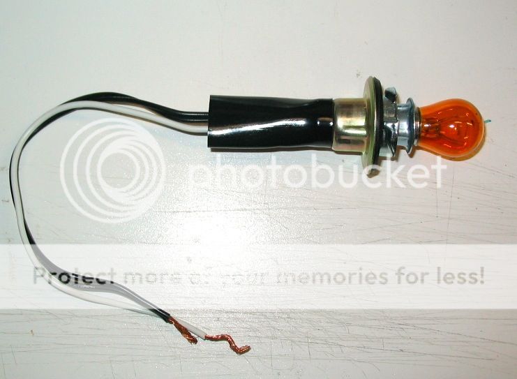
Ok...I finally got around to trying to get this thing to work with all the advice you guys gave me. Here are some detail pics so you can see what I am dealing with:
View attachment 108105View attachment 108106View attachment 108107View attachment 108108View attachment 108109
No matter what I do, I can't get this thing to work. I tried getting a seed light and even just connecting with a piece of metal to just test for continuity. Here is what I have found:
- All of the wire connections APPEAR to be good and strong
- All of the brass contacts APPEAR to be connecting the leads when the buttons are pressed.
- The car jump battery I use has good power and I clicked the leads of it together and got some healthy sparks
- The audible "armed" tone will not sound no matter what.
- The seed light or even igniter will not fire.
So...any ideas before I attempt to contact Aerotech about it?
Thanks
Sounds like you have a broken wire or bad connection somewhere that's keeping the circuit completely open regardless. It could be a broken wire in the leads somewhere between the battery and controller, or between the controller and the clips. Could also be a faulty "safety key" contacts/parts not making contact when the key is installed...
What you have is called an "open circuit". From the description you gave, I'd tend to think it's somewhere either in the safety key area not working correctly, or a broken lead... (the wires CAN break inside the insulation and the wire still appear to be intact... testing can determine if this is so). The reason I think this is because you said when you hook up a good battery and short the ignitor clips (hooking up metal between them to act as a low-resistance conductor in lieu of the ignitor), when you install the safety key, the beeper should go off. Now, it COULD be a faulty beeper, but if hit the launch button, electricity should flow (which isn't a good thing with a shorting bar (piece of metal) in between the clips) but if you installed an ignitor or test light between the clips, it should fire or light up... which you said it is not... therefore, the problem must be in a "common" area of the circuit, one which is in common to both the "continuity test" configuration of the circuit (when the key is installed and the launch button is not depressed, ie, the leads from the battery to the controller, through the buzzer, to the safety key, though the key, out the launch lead to one clip, thru the ignitor (or shorting bar, test lamp, etc) back through the other clip, back through the second lead, which usually goes straight through the controller or hooks directly to the second lead going back to the battery...
I don't have an interlock, but it works the same as an Estes controller, just slightly different parts... the buzzer is the small white 'can' connected by the thin leads to the two screws on either side of the launch button... With an ignitor (or shorting bar) hooked up, and the battery leads correctly hooked up (make sure you observe polarity, since most solid-state components like LED's and piezo buzzers usually will work when hooked up with the correct polarity, and WILL NOT if hooked up backwards... they act as a diode, which is a 'one way check valve' for electricity). When the safety key is installed, power should flow from the battery, in through one battery lead, to the screw on one side of the launch button, thru the buzzer, back to the other screw on the other side of the launch button, to one side of the safety key, through it, out the other side of the safety key, out thru one of the launch leads to the clip, thru the ignitor, back thru the other clip, then back to the controller thru the other launch lead, which should connect up with the second lead going back from the controller to the battery... trace the circuit and you'll see what I mean. If it doesn't do that (and if you've removed some of the wires and reinstalled them, you might have hooked it back up incorrectly... double check the circuit paths and make sure the electricity flows as I described... if you took any screws or wires loose in there). It's hard to tell exactly, because I cannot see the leads going out to the battery in any of your pictures, and I don't have an interlock of my own to compare it against.
The launch button on this one is very simple... when you press the launch button, the brass strip attached to the plastic button comes down and shorts the little angled posts sticking up from the screws on either side of the button, allowing electricity to flow unimpeded between them, through the brass metal bar, which "bypasses" the buzzer, allowing full battery power to go to the safety key, through it, out the other side, thru the lead and clip, thru the ignitor, back into the other clip and back thru the other lead, which should connect inside the controller to the second lead going back to the battery. Trace the circuit and you'll see what I mean...
If I could clearly see the battery leads, I could troubleshoot it for you from here...
The safety key on these controllers is unusual... Estes uses a metal "pin" (the actual metal "key") which is inserted between two narrowly spaced but seperate contacts on either side, which when the key is removed, creates a break in the circuit and isolates the battery, button, and continuity light from one of the launch leads, creating an "open circuit". When the key is installed, the metal key bridges the gap between the two contacts, allowing power to flow unimpeded to the ignitor, first thru the continuity light, and full power to the ignitor when the launch button is depressed, bypassing the continuity light. This is basically how all controllers work, to a point. I'm not exactly sure how the new Estes controllers with the "push in and hold" safety keys work-- I presume they bridge the gap in the same way as the old metal keys (since they use a metal pin) but have a rubber ring to "pop them out" unless held down to keep contact (added safety feature so you don't leave the key in and the circuit remain "hot" when hooking up the next rocket). Apparently the interlock uses some sort of a plastic "interlocking key" which is inserted to complete the circuit, probably by forcing two spring-loaded contacts together to bridge the circuit, which spring apart and open the circuit when the plastic key is removed... Not sure since I haven't worked on one, but it's reasonable... there's only so many ways these things can work. This is the first thing I would check.
Now, how can you test this to find out what's wrong?? You'll have to do some "investigating" and systematically prove each component is 'good' to find the problem. Start by tracing the circuits, as I described above, looking for any broken wires, loose wires, faulty connections, incorrect connections, shorts, opens, etc... anything that would allow the power to not go where it's supposed to, jump paths, or follow an incorrect path, or any spots where there is poor or no contact which would prevent power from flowing AT ALL. I'm about 95% sure you have an open circuit problem, probably in the safety key, or in one of the battery or launch leads... I'd probably wager on the safety key mechanism contacts... Once you've done a visual check of the circuit paths and the contacts and their conditions, if nothing has caught your eye, you'll have to start testing components. Unhook the battery from the controller, and remove the ignitor or shorting bar from the clips... you want open circuits for testing so you can test each branch of the circuit, each component or set of contacts, individually. For this you'll need a POWERED test light... Don't worry, it's not hard to do... all you need is a regular test light and a JUMPER WIRE, which is basically a piece of wire with a clip on each end... You can either make test jumper wires using extra wire and extra clips, or get pre-made ones for a couple bucks or so at the auto supply... to make your test light a POWERED test light, simply hook a GOOD 9 volt battery between one lead of your test light (I usually use an automotive test light which has a sharp pointy probe on one end and a wire with a clip on the other end, used to ground the test lamp when checking automotive circuits energized by the car battery.) If you have this type test light, connect one side of the test lamp to the 9 volt, and use the jumper wire to connect the other side of the battery to one side of the component being tested. Then touch the probe of the test light to the other side of the component-- say the buzzer... if the buzzer is good, it should either buzz, or the test light should come on. To test the launch button, connect the ground jumper wire to the batter to one screw on one side of the button, depress the launch button, and touch the test light lead to the other side (same as you would to test the buzzer-- Oh, BTW, reverse the test leads on the buzzer and test it BOTH WAYS to ensure that you get the correct polarity!) With the launch button held down and the battery ground jumper wire clipped on to the screw on one side, and the test light probe touched to the other side (and of course the test light ground or second lead clipped to the other battery post securely to form a complete circuit) the light should glow brightly. If it doesn't, make sure all the connections are good (test the test light and battery by touching it to the other screw (the one that the jumper wire is already connected to-- this should complete the circuit from the battery thru the jumper wire, to the probe, thru the test light bulb, and back thru the ground lead of the test light back to the battery-- if it doesn't light, figure out why-- dead battery or bad test light, or incorrect polarity (reverse the battery and try again).
If the buzzer and launch button check out okay, you know the problem isn't there... so you can ignore those parts from now on. Now hook the battery jumper wire ground to one side of the safety key contacts/switch. Make sure the test light ground is securely attached to the other side of the battery, and then touch the test light probe to the other side of the safety key switch where power goes out to the launch lead... with the key removed, the light should NOT be on. Insert the safety key (and hold down if necessary-- again, I don't have an interlock so I'm not sure if you have to do that). With the key securely installed, the light SHOULD be on... if it's not, double check your jumper wire/battery connections, and test again... if not, check the contacts and stuff inside the safety switch for bent, broken, or corroded parts. Fix and repeat-- Assuming that checks out as good, now you have to start testing the leads. Start with the battery lead from one battery clip connected to one lead wire going into the controller... clip the ground wire to this clip, make sure it's not touching anything else, and follow that wire with the probe, up it's length and into the case, to where it should connect up to a screw... touch the light probe to that screw... the test light should lite up... (again, make sure the jumper wire and battery and test light ground connections to the 9 volt are all good-- you MUST make a complete circuit). If the lite does NOT light (and you're ABSOLUTELY SURE that you've followe d the RIGHT wire, and didn't jump to the other one at some point accidentally) then you have a broken wire somewhere in the insulation. Check the second battery lead wire the exact same way, move the battery jumper ground to the other battery clip, trace the wire to its other end (whatever it connects to-- it could go straight through the controller out to one of the launch clips). Test probe the other end... lamp should lite-- if so, you're good... if not, check your test circuit, double test, and if still no light, you've probably found you're broken wire. Test the launch leads the same way... clip the battery jumper ground to one ignitor clip and trace the wire back to whatever it connect to, and then probe that end. It should light. Same thing with the other ignitor clip and lead. Then, test the wire connecting the launch button with the safety key switch-- clip the ground to one end, and probe the other end. It should light up.
Do the tests systematically and follow the electricity as it would flow through the circuit, and I'm sure you'll find the problem. If you have more problems, PM me and I'll walk you through it...
later and Good luck! OL JR
")