Modular Raven AvBay

The Rocketry Forum

Help Support The Rocketry Forum:

This site may earn a commission from merchant affiliate links, including eBay, Amazon, and others.

troj

Wielder Of the Skillet Of Harsh Discipline
TRF Supporter
Joined
Jan 19, 2009
Messages
14,955
Reaction score
1,287
One of the things I've always wanted to do, but have never gotten around to, is to come up with a modular, drop-in avbay that I can swap readily between rockets. This is to avoid building custom sleds for each and every rocket, and having to remount electronics.

Instead, I wanted one module that I build for, then just drop the module in the particular rocket.

With the new Raven AvBays, I realized I have the platform for just that.

I decided to use the 29mm as it's small enough to fit inside a 54mm tube fairly easily, while the 38mm doesn't leave much room inside a 54mm tube for other attachments.

-Kevin
 
I'm doing the initial work on a Performance Rocketry Intimidator 4 that I just picked up. With a 4" airframe, two of the 29mm modules will easily fit side-by-side in the coupler. There will be a tremendous amount of void space in the coupler, but that's okay.

The first step is to make the cutouts in the bulkheads for one end. I want to make a "cap" that sits on top of the module and is used to retain it in place. So the inner bulkhead needs a 29mm hole, and the outer bulkhead needs a slightly larger hole.

The inner bulkhead cut really nicely, but the outer wandered a bit towards the end of the cut, so the holes are a bit sloppy. Fortunately, in this case, that doesn't matter, so I didn't worry about it. It's not pretty, but it'll work.

Pictures here show the bulkheads marked and with pilot holes drilled, followed by each bulkhead with its holes, then the stack, the way they go on the end of the coupler.

-Kevin

ab1.jpg

ab2.jpg

ab3.jpg

ab4.jpg
 
I guess I kind of did that by default. I build my original sled for my L1 bird that was less then 2" ID in the av-bay. I then made the threaded rods in my 4" spaced so the same sled would fit in there. The original L1 bird is no more, but now I have av-bays in several 3" & 4" rockets that are still based on that original design and the sleds can move from rocket to rocket.

I use a couple of pieces of closed cell foam pushed over the threaded rod to cushion the ends of the sled if the av-bay is longer.
 
The next pictures show the basic components -- the bulkheads, epoxied together, along with the tubes to receive the modules (29mm motor mount tubing) and the actual avbay tube. Featherweight sells 29mm tubes already cut to the right length, so I'm going with those, rather than sourcing my own and having to then cut them properly.

Next up are the receiver tubes tacked in place on the bulkhead, so that I can mark and drill other holes.

Final picture shows the bulkheads with the u-bolt for this end in place. The metal strap for the u-bolt wouldn't fit, due to the spacing of the tubes, so I used a pair of fender washers. One required a slight cutout with the Dremel to fit up against the tube. The center hole on the bulkhead will be used to pass wiring to the other bulkhead, and the two smaller outer holes are for the allthread that runs to the bulkhead at the other end of the coupler.

-Kevin

ab5.jpg

ab6.jpg

ab7.jpg
 
First picture here shows a module almost fully assembled. Note the nuts on the bottom are flush with the end of the allthread. This is because these nuts will sit on a support at the bottom of the receiver tube.

Also at the top is a plywood bulkhead. This fits inside the larger opening in the larger diameter bulkhead. This serves two purposes -- one, it provides a good seal at the top of the compartment, to keep gasses out, and two, it provides protection for the passive bulkhead from the avbay.

Second picture shows the module dropped into the receiver tube, without the plywood bulkhead.

Final picture shows what this will look like once it's installed in the coupler.

-Kevin

ab8.jpg

ab9.jpg

ab10.jpg
 
Kevin,
That's very clever!

I've thought about this too, and from this point on, any rocket we build 4 inches in diameter or larger will be using the same sled as our extreme darkstar, unless we need 3 altimeters or timers for some reason.


Braden
 
A bit more work today.

First pic shows the Raven module with its vent holes drilled. Each module vents out into the coupler, and the coupler itself vents to the outside of the airframe. Therefore, the size of the holes between the coupler and the module needs to be sufficient such that when the module is installed, it always has enough airflow between the module and the bay. Otherwise, the baro sensor on the Raven won't be accurate.

Because of this, I oversized the holes and placed them such that no matter how I turn it, I have lots of open space. Yes, this weakens the coupler, but there is no structural load on the coupler, so this isn't an issue.

In addition, I learned that drilling clean holes in Blue Tube is a pain in the patoot! The stuff is almost a bit gummy. I think a drill press and very sharp bits are pretty much mandatory.

The tubes the modules go into have cleaner holes, but they're not perfect. Once again, a drill press would help. The nice thing? These holes are all away from the airflow outside the airframe, so I knew they didn't have to be perfect.

Second tube shows the receiver components for the Raven modules. I've epoxied the support bulkhead to the receiver tubes, as well as to the bulkhead that goes at the top of the coupler. This provides a solid support for everything.

Third picture shows the allthread permanently attached to the bottom bulkhead, along with the nuts that help support the bulkhead at the bottom of the receiver tubes. These support nuts are held in place with CA, to keep them from moving.

Once the epoxy cures, I'll work on wiring....after I get more wire, as well. :)

Next time I do this, I'll have someone with a laser cut the vent holes for me, so they're nice and clean. Either that, or at the very least, I'll beg or borrow a drill press.

-Kevin

ab11.jpg

ab12.jpg

ab13.jpg
 
Did you hire a cut rate beaver to drill those holes? :eek:

I've got the card of one that is just a step above lowest bidder :)

Edward
 
Did you hire a cut rate beaver to drill those holes?

Yeah, the bits grabbed really badly. A drill press would allow a lot better control.

The Blue Tube still won't drill for squat, even with a drill press, I bet. It's probably gonna take a laser to get a nice hole in that stuff!

-Kevin
 
Have you tried a step bit? I find they work really well for enlarging holes.

I've used them on almost every airframe and they cut cleanly.

Edward
 
It looks like there is just enough flex in the Blue Tube for the material to shred rather than cut. Next time you need to drill it, try to find a piece of either PVC or dowel that just barely fits inside, and use that as a backer before you start to drill.

Great design for the av-bays!

G.D.
 
It looks like there is just enough flex in the Blue Tube for the material to shred rather than cut. Next time you need to drill it, try to find a piece of either PVC or dowel that just barely fits inside, and use that as a backer before you start to drill.

The problem is actually more on the outside that the inside -- the bit really pulls the material up and curls it. It flexes, rather than cuts.

I think the trick will be a combination of things -- a sleeve it fits inside, along with a support on the inside, and possibly the step bit that Edward suggested.

Next rocket I build that uses these, I'm going to try some things when making the holes. I'll probably get more of the Blue Tube and work on cleaner holes, too.

-Kevin
 
Very cool idea. But how are you connecting the other side of the Raven Module? I have the same Raven 29mm setup and would like to customize it for a 4" Av. Bay
 
You know, it's amazing just how little room there really is on a 4" diameter bulkhead.... :eyepop:

Wiring - that's the fun part. One thing I wanted to avoid was constantly connecting and disconnecting bare wire ends, as over time, they'll break. So, I decided to use ring terminals to hold everything securely in place.

I made the wires long, to facilitate getting them through the tube. I wish I had made them about 6" longer -- it would've made assembly easier, as I would have had more slack to work with!

First pic shows the bottom (drogue) end. Second pic shows the top (main) end, with one module installed.

I still need to drill vent holes through the side of the tube and attach the mechanism for holding the modules in place.

-Kevin

ab14.jpg

ab15.jpg
 
You know, it's amazing just how little room there really is on a 4" diameter bulkhead.... :eyepop:

Wiring - that's the fun part. One thing I wanted to avoid was constantly connecting and disconnecting bare wire ends, as over time, they'll break. So, I decided to use ring terminals to hold everything securely in place.

I made the wires long, to facilitate getting them through the tube. I wish I had made them about 6" longer -- it would've made assembly easier, as I would have had more slack to work with!

First pic shows the bottom (drogue) end. Second pic shows the top (main) end, with one module installed.

I still need to drill vent holes through the side of the tube and attach the mechanism for holding the modules in place.

-Kevin

Wow, I wasn't expecting to see any of those wires. Why not just connect the deployment charges directly to the av-bay threaded rods? (that was the intention of the av-bay design).

You could connect the charges to each end of the av-bay, and then insert the completed av-bay into the av-bay holder tubes.

The top charges, I could easily do that way (and probably should have). The bottom charges, I'd have to feed them up through the coupler tubing.

The goal is to not have to fish wires through 8+ inches of coupler.

Though if I were to run a thin conduit the length of the coupler, that would make that easy to do. Hmmmm.....

Time for a redesign, methinks!

-Kevin

Is there a way you could just install the av-bay, with the bottom-side charges already installed, from the top?
 
Is there a way you could just install the av-bay, with the bottom-side charges already installed, from the top?

Not really -- the coupler, in this case, is about 10" long, and my goal is to not have to disassemble the coupler.

But, I thought about it, and have an easy answer -- run a conduit through the coupler. In this case, just a piece of 1/4" brass tubing.

What I did was cut a piece of tubing a bit longer than the coupler, then epoxy it into the receiver assembly on the forward bulkhead, flush with the forward bulkhead. When run through the coupler, it sticks past the rear bulkhead by about 3/4". This makes it easier to line the tube up on those rare occasions when I do need to disassemble the coupler.

With this method, I just push the wires through the conduit and attach them directly to the allthread terminals. This reduces that rats nest of wire, which I wasn't very happy with.

In the photos, I've pushed some Cat 5 pairs through the conduit, in place of actual leads. It's quick, it's easy, and it'll just work.

Now that I have something down, I'm working on cleaner parts for version 2 -- this one is basically a prototype, and I think it's gonna work out well.

-Kevin

ab20.jpg

ab21.jpg
 
If there's going to be a "next time", here's a different idea for you to consider:

dualravenav-bays.gif


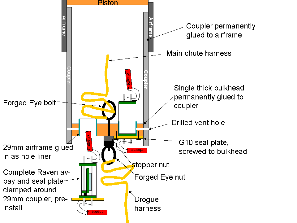
At least, this is how I would do it. There would only be a single bulkhead in the whole rocket, and the charges would fire on either side of it, from 2 29mm av-bays that would be inserted from the accessible end. You can get each av-bay ready away from the rocket, including installing the charges, and then pop them into the bulkhead when you're ready to launch. There would be short sections of 29mm airframe tube that would be glued into the bulkhead to form the seal around the 29mm av-bays, along with a seal plate that would be attached on one end of each av-bay to make each av-bay a "T."

This design appeals to the minimalist in me, because the whole av-bay volume in this 4" rocket is just two 2" long, 29mm sections. You can fill up what would normally be the rest of the av-bay volume with shock cord, etc, which would save several inches of rocket length. The coupler could be extra long if you wanted it to be, without making the rocket any longer, wasting any more volume, or adding any threaded rod mass The shock cord attachment to the rocket is super-strong, with a very minimized amount of metal that has nothing to do with the altimeter mounting.
After the flight, just pull out the av-bays to look at the data and reload with new charges. You don't even need to dis-attach the shock cord, which means you can just knot the cord onto the eyebolt/eyenut, eliminating quick links for more mass and volume savings.

A variation on this would make the thick bulkhead removable for easier access for cleaning the main chute tube and inspecting/installing the shock cord. It could be screwed into the coupler with flush screws on the outside of the coupler, or itself screwed onto a thin retaining ring that would be glued to the coupler. Or it could be two thinner bulkheads that are clamped around a thin inner ring via the shock cord bolt.
 
Adrian, your method would definitely work, but as you state in your message, you tend towards a "minimalist" approach.

Personally, I'm not a big fan of pistons, and I like couplers to be removable, as it makes things easier to work on, rather than sticking my arm down a tube.

That said, once I get some parts cut, I'm tempted to build one both ways and thoroughly document both -- options are good, and I think this would be a useful thing to have documented, to give folks ideas for how to use these little gems!

-Kevin
 
Its starting to make a little sense to me, but I'm still a little confused I think.

In pic #1 and#2 in post #8 (the beaver cut holes :wink:) I think Kevin was just hogging out material so he wouldn't have to be careful to put the little av-bay sled doo-hickeys into the fabricated av-bay holder bulkhead plate thingy. That whole thing (2 plates and 2 tubes) go into a standard-ish av bay. Is the 2 plate and tube assembly sealed to the regular av-bay or is the whole standard av-bay sealed like in a standard application.

With Adrian's proposed design, would the long/small diameter vent hole pose any problems? I think I traced a problem back to poorly drilled vent holes on a flight years ago. I basically hired Edward's beaver to do mine and they possibly aliased the pressure in the bay. I cleaned them up and never had an anomaly like that again, so I assume that was an issue.

I look forward to both of these concepts being fleshed out some more.

Thanks!

Sandy.
 
In pic #1 and#2 in post #8 (the beaver cut holes :wink:) I think Kevin was just hogging out material so he wouldn't have to be careful to put the little av-bay sled doo-hickeys into the fabricated av-bay holder bulkhead plate thingy.

Correct. The goal is such that no matter how the module tube is oriented, proper venting will take place.

That whole thing (2 plates and 2 tubes) go into a standard-ish av bay. Is the 2 plate and tube assembly sealed to the regular av-bay or is the whole standard av-bay sealed like in a standard application.

The receiver portion (bulkhead/receiver tube sandwich) is mounted in the forward end of a coupler. The coupler has a bulkhead on the other end, with recovery attached to it. The idea is that the modules are dropped in, with no need to disassemble the coupler assembly.

Varying size rockets can be built, with a coupler appropriate to that rocket, and the modules just drop into the receivers in that coupler.

With Adrian's proposed design, would the long/small diameter vent hole pose any problems? I think I traced a problem back to poorly drilled vent holes on a flight years ago. I basically hired Edward's beaver to do mine and they possibly aliased the pressure in the bay. I cleaned them up and never had an anomaly like that again, so I assume that was an issue.

For Adrian's, rather than one thick bulkhead, I'd use two thinner ones, with a gap (1/4" would be sufficient) in between them. Put holes in the receiver tube in line with that gap, and holes within the modules, as well. Or, as an alternative, remove the receiver tube entirely from within this gap, and then alignment of holes is a non issue.

That gap then needs to be vented to the outside. When calculating the vent hole size, you need to calculate for a bay that's 1/4" long and the diameter of the coupler, plus two tubes each of which is the size of the Raven module. So, those external vent holes don't need to be very large at all.

Where a lot of the difference between Adrian's method and mine is that, as Adrian stated, he's a minimalist. I think a lot of this comes from the fact that he's into maximizing performance, and he's good at it.

My way adds significantly more weight (allthread and nuts, anyone?), but it fits more in with the way I fly -- I don't typically worry about maximizing performance.

I've got someone working on hiring a squirrel to gnaw holes for me, as they tend to not be as messy as beavers. Once I have clean holes puzzled out, I'll build more prototypes and fully document out both ways of doing things.

-Kevin
 
If there's going to be a "next time", here's a different idea for you to consider:

dualravenav-bays.gif

I really like this scheme. On the aft (accessible) end, there is a seal disk to keep ejection gases out of the avbay. But on the fore end, it seems to me that there is nothing keeping the main ejection gas from seeping between the avbay coupler and the receiver tube, possibly entering the altimeter vent. Is an o-ring needed to seal between the ebay coupler and its receiver tube, or am I overthinking this? Also do the Raven bulkeads need to be protected from the ejection charge? In your figure, the aft Raven bulkhead is protected by the seal disk, but the fore end is not.
 
I really like this scheme. On the aft (accessible) end, there is a seal disk to keep ejection gases out of the avbay. But on the fore end, it seems to me that there is nothing keeping the main ejection gas from seeping between the avbay coupler and the receiver tube, possibly entering the altimeter vent. Is an o-ring needed to seal between the ebay coupler and its receiver tube, or am I overthinking this? Also do the Raven bulkeads need to be protected from the ejection charge? In your figure, the aft Raven bulkhead is protected by the seal disk, but the fore end is not.

The forward end is sealed by the bulkhead of the Raven AvBay. When assembled, it's a module with the Raven bulkheads on either end of a tube.

-Kevin
 
I really like this scheme. On the aft (accessible) end, there is a seal disk to keep ejection gases out of the avbay. But on the fore end, it seems to me that there is nothing keeping the main ejection gas from seeping between the avbay coupler and the receiver tube, possibly entering the altimeter vent. Is an o-ring needed to seal between the ebay coupler and its receiver tube, or am I overthinking this? Also do the Raven bulkeads need to be protected from the ejection charge? In your figure, the aft Raven bulkhead is protected by the seal disk, but the fore end is not.

The contact between the bulkhead and the coupler edge provides adequate sealing from the charge. As long as the charge isn't in direct contact with the bulkhead, it won't be damaged from it, in my experience. The separate seal plate in the diagram is just a way to hold the av-bay in place, though it will provide some additional protection and sealing.
 
Thanks for the quick answers. I am satisfied that the Raven bulkheads seal against the avbay coupler. My remaining question is whether the relatively loose fit between the avbay coupler and its receiver tube will be adequate to protect the vent hole. In the attached figure, I have shown nasty red ejection gas blowing between the coupler and receiver tube and finding its way to the vent hole.

On the way up, air would be blowing out of the vent, but on the way down (when the main charge blows), air will be blowing into the vent, possibly carrying ejection gas with it. Perhaps, though the seal is not airtight, it is good enough to protect the altimeter?

dualravenav-bays-close.png
 
Thanks for the quick answers. I am satisfied that the Raven bulkheads seal against the avbay coupler. My remaining question is whether the relatively loose fit between the avbay coupler and its receiver tube will be adequate to protect the vent hole. In the attached figure, I have shown nasty red ejection gas blowing between the coupler and receiver tube and finding its way to the vent hole.

On the way up, air would be blowing out of the vent, but on the way down (when the main charge blows), air will be blowing into the vent, possibly carrying ejection gas with it. Perhaps, though the seal is not airtight, it is good enough to protect the altimeter?

It's not really clear in the original picture, but I had in mind to glue in a short section of airframe tube into the bulkhead to act as a liner to prevent the gas path you're showing.
 
Back
Top