8" MLAS Prototype

The Rocketry Forum

Help Support The Rocketry Forum:

This site may earn a commission from merchant affiliate links, including eBay, Amazon, and others.

El Cheapo

Well-Known Member
Joined
Jan 20, 2009
Messages
1,658
Reaction score
7
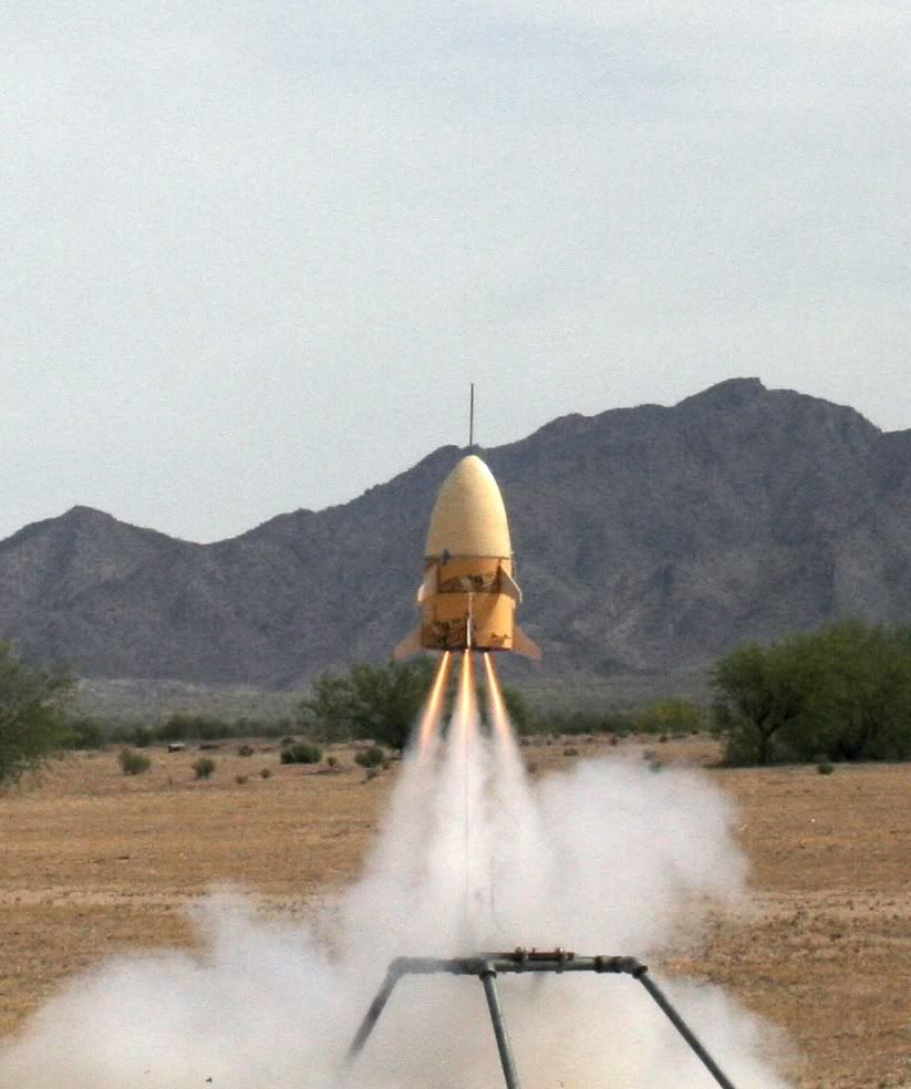
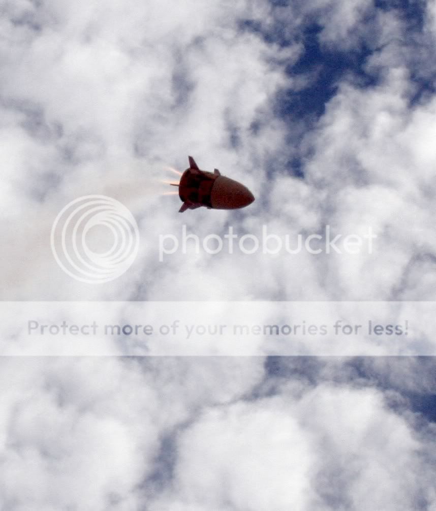
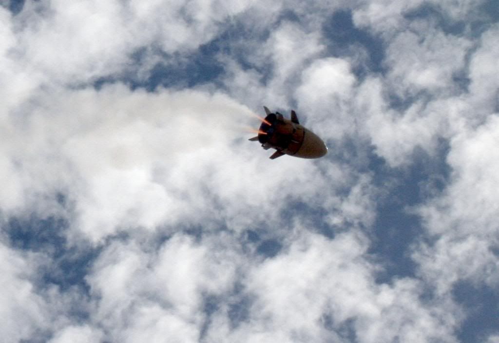
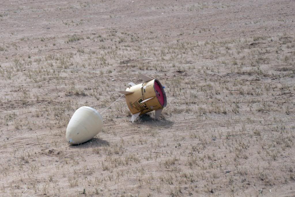
If you've checked my signature link, you know that I'm on the ARC (Arizona Rocket Consortium) build team. This weekend we flight tested our first prototype on our way to building a 1/2 Scale NASA MLAS (Mass Launch Abort System). Our goal in this first model was to simulate flight characteristics of the vehicle itself as well as the canted cluster configuration. Early on we also decided to add to the difficulty level by simulating drag separation of the Capsule and Shroud as well.

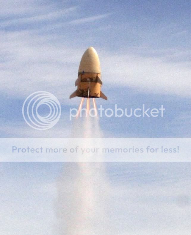
Canted motor configuration as well as shroud lines which bring the motor cage in upside down under chute. Motor choice for this flight was D12-3's.

IMG_1806.jpg


Motor Cage and Coast Skirt. One thing that cannot be seen is we ducted the ejection charges into two pairs, one to separate motor cage from coast skirt and the remaining two to separate the Capsule and Shroud from the coast skirt.

IMG_1807.jpg


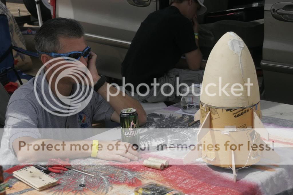
Motor Cage, Coast Skirt, Capsule and Shroud ready for assembly

IMG_1804.jpg


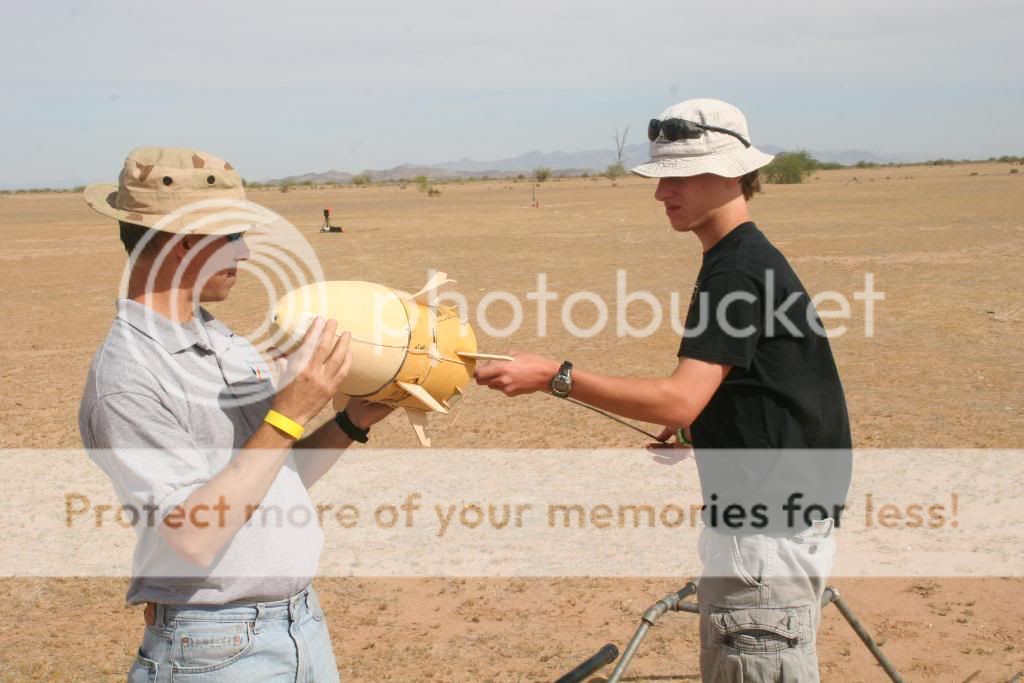
Rick McKee showing the location of the 12oz of noseweight

IMG_1805.jpg


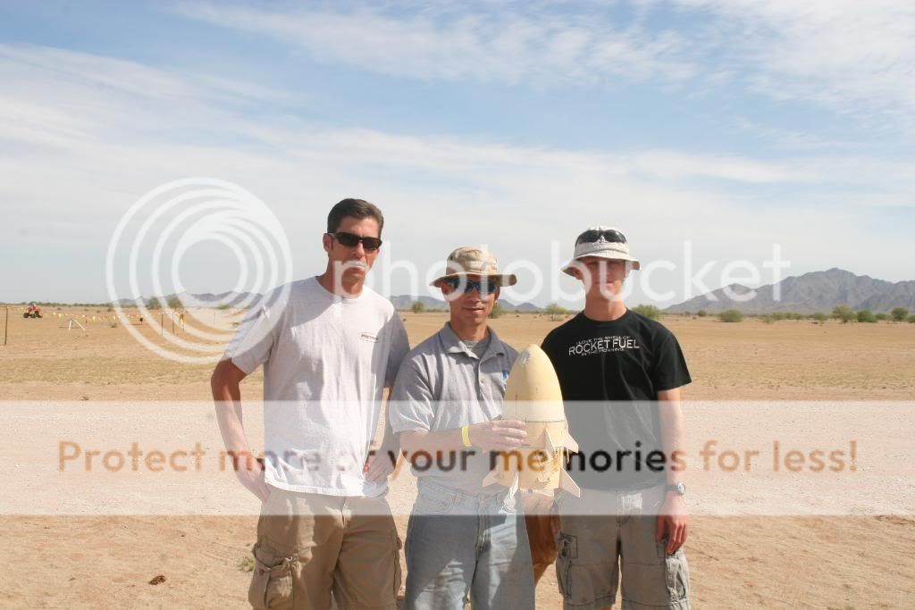
Team ARC Left to Right: Tom Seemeyer, Rick McKee, Shon Michael. We have some additional "Super Geeks" coming on board down the road to help electronics, deployment as well as the overall construction of the 1/2 scale. Luckily for me, goofy hats are not part of the required dress code.

IMG_1808.jpg


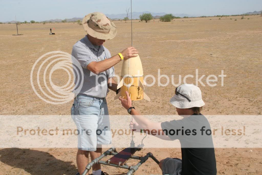
All prototypes and the 1/2 scale will have a center launch lug. Running straight through the foam proved to be a bad idea without a central lug as it stuck a bit but worked for this test.

IMG_1811.jpg


IMG_1814.jpg
 
Last edited:
Flight pictures

IMG_1819.jpg


IMG_1819c.jpg


All four lit by Q2G2 Igniters

IMG_1820c.jpg


IMG_1821.jpg


IMG_1821cc.jpg


Starting to lean a bit. Apparently Rocsim was off on the nose weight but the wind gusts could not have helped.

IMG_1822.jpg


IMG_1822c.jpg


IMG_1823.jpg
 
And She's over

IMG_1824.jpg


IMG_1826.jpg


IMG_1826c.jpg


IMG_1827.jpg


IMG_1827c.jpg


The capsule did separate and landed under chute

IMG_1828.jpg


Built well, no damage. Here you can see the ducted ejection ports for the Capsule and Shroud.

IMG_1829.jpg


Isis the Rocket Dog Mascot checks for damage

IMG_1830.jpg


I call this: "Pondering with caffeine" A few tweeks and she'll fly again shortly. Work has already begun on our 24" prototype.

IMG_1831.jpg
 
Great job! Any pics of the separation / recovery?

It partially separated under power. The capsule did what it was supposed to do which was "escape" :D 
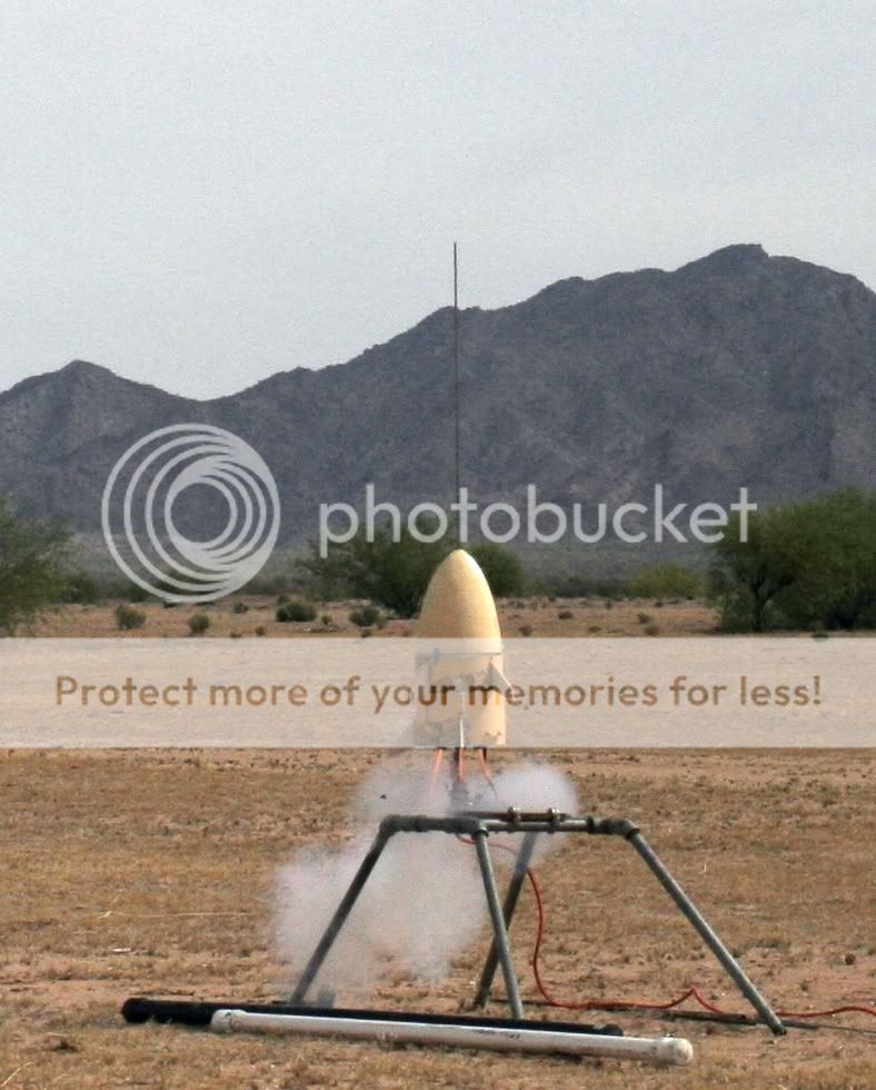
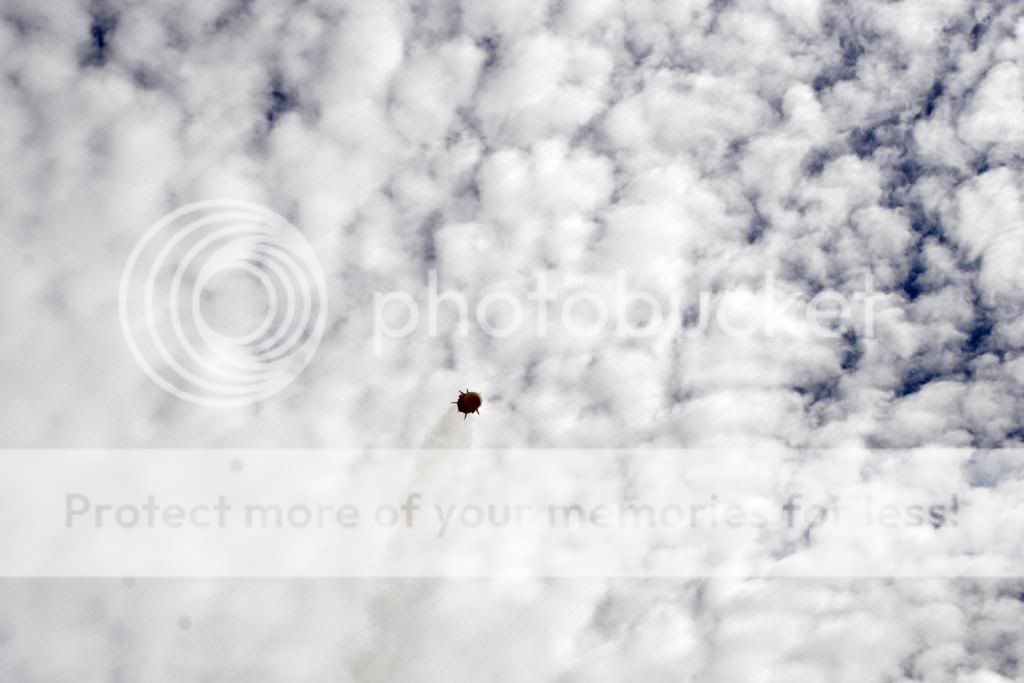
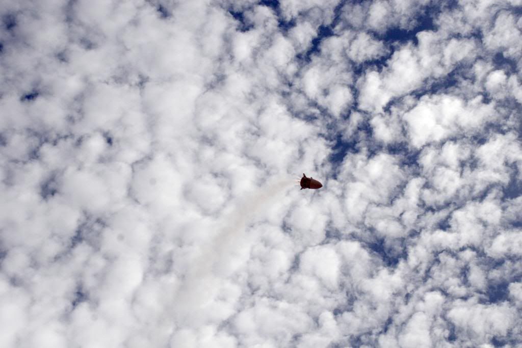
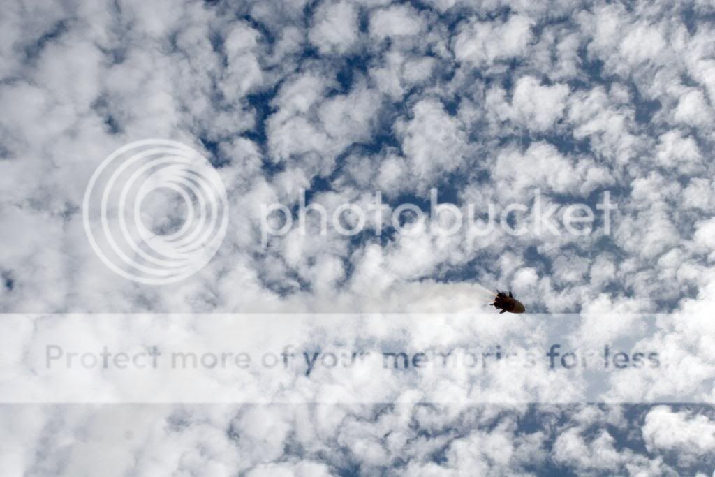
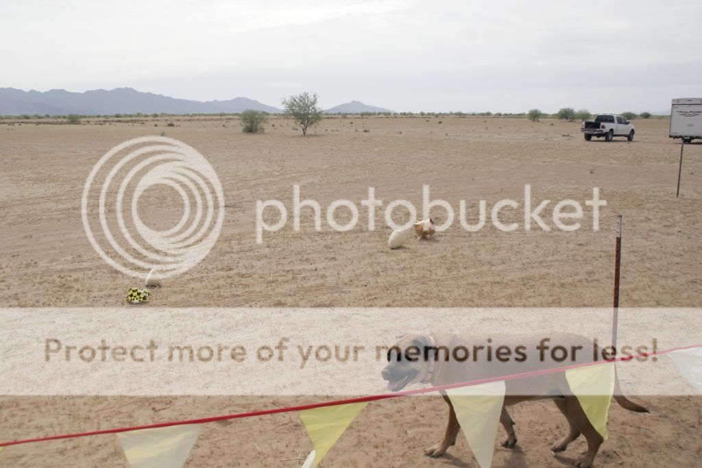
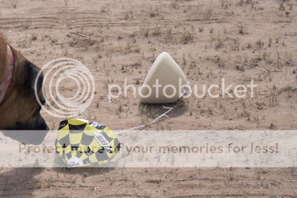
and came in under chute. The rest pranged under power.
 
cool rocket! cool flight! cool pictures... looks like a success all around...

thanks for posting...
Great launch site.... what is your waiver?
 
I'm not sure what Rocsim said as the the other members ran it. I believe it's moot anyway because I don't think it accurately represents canted motors. Wind was gusting 5-15. We waited on the pad for a break. Hindsight we should have waited for dead calm but that wouldn't have been any fun.

In our minds, it was not unsuccessful by any means. We now know exactly what changes to make to this diameter prototype which will help in the 24" as well as the 1/2 scale.
 
Excellent flight report. Glad to see yours was more successful than my 8" MLAS. Last minute change in motor made mine way underpowered :( Mind if I swipe a photo for my blog?
 
Excellent flight report. Glad to see yours was more successful than my 8" MLAS. Last minute change in motor made mine way underpowered :( Mind if I swipe a photo for my blog?

Go for it!!!! We learned alot from the info you supplied us with.
 
I'm not sure what Rocsim said as the the other members ran it. I believe it's moot anyway because I don't think it accurately represents canted motors.

Nope ... you'd have to "de-rate" the motors to account for the component of thrust lost to the cant angle. As it was, it performed far better off the pad than I would have expected, especially given the wind.

In our minds, it was not unsuccessful by any means. We now know exactly what changes to make to this diameter prototype which will help in the 24" as well as the 1/2 scale.

Not at all! Great flight and a really cool project! Keep us up to speed with your progress on the upscales.
 
Way cool and ambitious project!

Tim, their nose/capsule fairing was no where as "precise" as the real one and it looks like it flew just fine.:wink:

Engineers, can't live with 'em, not allowed to shoot 'em.

View attachment FINAL MLAS DESIGN.pdf
 
Gordon, you are correct, Sir. We already had the shroud and capsule spun before we got your measurements. The 24" will be accurate.
 
Gordon, you are correct, Sir. We already had the shroud and capsule spun before we got your measurements. The 24" will be accurate.

My point is the shape wasn't as critical to the stability as the engineers first thought.

It looked like yours flew just fine.
 
Clay. Our waiver, I believe, 6,800 with a call in to 11,000. It's an amazing launch site with "O" capability

The 1/2 scale will be 18' high x 8' diameter.
 
Tim,

If I remember correctly didn't you once write that Rocksim simulations of your model came pretty close to the actual NASA simulations of the real MLAS?


El Cheapo,

Will the consortium's 1/2 scale model simulate the Chute-A-Palooza aspect of the MLAS flight?


Steve
 
nice project.

Looks like it went unstable late in the burn.

I’m attaching a cropped and modified version of one of the photos to try to enhance the smoke trail. I did it to show that the model seems to make a sudden severe angle-of-attack change to the airflow that does not seem to be anything like weathercocking.

So, it may have been neutrally stable and went unstable late. Or, well, tried to go unstable.

Which would mean for the big model you’d need to have the CG more forward. Which I know is not easy for a model like this. Making the back half of it as light as practical will help.

- George Gassaway

MLAS-modified.jpg
 
Gus, I believe we have Tim's Rsim file. Rick had some problems initially with the file and his version of Rsim and is planning to speak with Apogee about It.

As far as replicating the full scale MLAS chutapaluza, the answer is, "yes" as much as possible. We have yet to figure out whether or not the shroud and capsule will initially fire drogue chutes for upright stabilization or just pop the mains. There will be one addition which is bringing the boost skirt in under chute (inverted) versus free falling like the NASA model. Our Inutial calculations call for a minimum of 3,500' for all events to take place but we are shooting for just over a mile to be safe.

We are currently at the N's limit for our field with for M2500's which is a tick over 40,000N's. If we need any more than that our home launch site will not be useable.

George, your point is definitely one that I will bring up. This model was still under power when it impacted so I'm not sure how far into the burn it was. I was behind the lense so tough to say for me at this point because I have not seen the video yet.

As far as weight we are going as light as possible. That has really been my contribution so far. I have a good background in fabricating race cars so my thought process is to build light and strong with minimal materials.

The boost skirt will consist of mainly fiberglass and honeycomb for the fins. The motor cage will closely represent the actual vehicle with filled carbon fiber tubing.

Forgive the typos, I'm replying on my phone.
 
Last edited:
Very cool project.

Sonotube wth 4 D-12's.

Didn't think you would get the altitude you did....but nice!
Did I miss the all up weight -loaded...?
...and did you use base drag in the Roc Sim for this little fat fellow?


Bookmarking this thread.
 
Last edited:
Tim,

If I remember correctly didn't you once write that Rocksim simulations of your model came pretty close to the actual NASA simulations of the real MLAS?

Yep ... that's true. The CP location predicted by RockSim using its stability equations (the non-Barrowman method) is almost exactly the same as the one we derived from wind tunnel data for the real vehicle. And its much further forward than anyone who wants to fly one of these would like.

The MLAS forward fairing is a Sears-Haack profile, flattened at the nose to drive the CP aft ... flatter would have been even better, but the aero guys didn't want to push it much more than that due to the drag penalty. The funky "bulge" near the aft end of the fairing is the result of blending the Sears-Haack taper to a true cylinder - we needed about 12" of cylinder there so we could install a frangible sep joint. Gordy's drawing accurately represents the flight vehicle, so stick to that with your upscale, EC, and you'll be doing about as well as you can from the CP perspective. And George is right about the trim: you need to minimize weight in the aft and add ballast up front to pull the CG forward.

My guess, based on your pictures, is that the model CP was further forward than it should have been (due to the fairing shape, probably) and the CG a little too far aft. It shifted aft even further as the motors burned, so you probably reached a tipping point and became neutrally stable as George observes. Even perfectly trimmed there's very little margin there. It looks underpowered to me too ... I would have expected a straight boost to burnout, then drag separation of the boost skirt. If the trim is right, the fairing and forward fin assembly (the coast skirt) should be stable on their own.

Good luck with this ... my personal bias aside, I think it's a great project!
 
Last edited:
I think the D's will be ok. We weren't expecting any more than 300' out of this one. Just for good measure we've got four cases between is and are going to send It up on F39's next time.

Sounds to me like we should spin a new shroud as well.
 

Latest posts

Back
Top