Launch button momentary on switch

The Rocketry Forum

Help Support The Rocketry Forum:

This site may earn a commission from merchant affiliate links, including eBay, Amazon, and others.

Seanson

New Member
Joined
May 16, 2018
Messages
3
Reaction score
0
My first post here.

I'm getting back into rockets after a 30 plus year hiatus.

I want to make my own launch controller, and have found all the parts that I need, except for a push button momentary on switch for the launch button.

Most of the ones I have found are only rated 3a at 12vdc.

What have you guys used for a push button launch switch?
 
Last edited by a moderator:
I was thinking I might have to go with a relay. I can't quite get my head around how to wire it though. In most of the schematics that I have looked at, to me, it looks like the switch is still getting full current.

Do any of you have a super simple way of explaining how to add/wire the relay?
 
Ha... Me too! Only use that for triggering a high current relay or circuit though. It can’t handle any significant current.

You won’t find high current momentary switches. Get a low current switch and use it to flip a high power relay. High power 12v relays are easy to find - cars are full of them.

That switch is rated at 50 Amps.
 
Do any of you have a super simple way of explaining how to add/wire the relay?

The coil side of the relay is one circuit, as if the coil were the igniter. The contact side of the relay is another circuit, as if the contacts were the switch. Very simple to wire up. You should use separate batteries for each circuit.

If you use heavy wire, such as 16g orange electrical cord, and you don't use more than 50ft, you don't need a relay.
 
That switch is rated at 50 Amps.

You could pull a lot more than 50amps depending on the igniter and the battery.

That’s switch is cheap Chinese junk really. I opened mine up to see how it was wired. I wouldn’t run 1amp through it. It might survive 50 Amps once or twice.
 
You could pull a lot more than 50amps depending on the igniter and the battery.

That’s switch is cheap Chinese junk really. I opened mine up to see how it was wired. I wouldn’t run 1amp through it. It might survive 50 Amps once or twice.

I've lit 100's of igniters directly with that switch. No, you won't pull very many amps firing an igniter. 5 amps is plenty. If you want to cluster, use a relay.

In either case (direct or relay) it is best to protect your wiring and components from a dead short. Use an automotive auto-reset thermal breaker. It won't kick out for normal ignition time & current, but will break the circuit quickly if there's a short. Prevents melting of wires and releasing magic smoke from the box.
https://www.amazon.com/gp/product/B000Q0AVHQ/?tag=skimlinks_replacement-20
 
Last edited by a moderator:
The coil side of the relay is one circuit, as if the coil were the igniter. The contact side of the relay is another circuit, as if the contacts were the switch. Very simple to wire up. You should use separate batteries for each circuit.

If you use heavy wire, such as 16g orange electrical cord, and you don't use more than 50ft, you don't need a relay.

Is a single aa battery good to power the switch side of the relay?
 
Is a single aa battery good to power the switch side of the relay?

No, a single AA battery is only 1.5V. You need the minimum voltage required by the relay coil. Typically, we use low-cost automotive 12V relays. But, there are also 5V/6V relays that would work with four AA batteries in series in a battery holder.

I've been using 3-cell Lipo R/C batteries in my launch controller. A charger and two batteries will cost around $60.
 
I use a phono receptacle/plug as the removable switch, a momentary 2A switch for launch and some LEDs for power and continuity in a project box the size of a single outlet box. One 6 ft. wire goes to the Automotive starter for power and the other is 50 ft. of lamp cord to the igniter. I've use this on single and clusters up to 4 motors.

The Automotive starter has many uses and works like a car battery for the launcher. The small controller box can be coiled up with the wire for easy transport and storage. You just need to remember to bring the shorted phono plug along or the whole thing is useless.
 
So I've been reading a whole whack of thread on Launch Controllers as I'm looking to build my own for this summer - figured I'd tag along this thread since it's actually recent and relevant.

We want to do 12V, and it's only for personal use (no big club launches), so the demand for lots of runs (and ergo a huge battery) isn't there.

I'm pretty good with electronics - but I guess the one question I have is how much current I should be setting this up for. We only ever plan to fire off G motors as a maximum - but even that's still a maybe - the largest we're doing now are E's.

Cheers

Even for a single run a nice large battery is preferable. Sure, you can fire an igniter for even the larger motors with a few AA batteries (depending on the length of your launch cable). The difference is having a rocket light within a second of the button being pressed vs having a rocket light after holding the launch button down for several seconds.

Personally, I like a long cable because I think rockets look better from the side rather than from the rear end of the rocket. I don't use a relay, but probably will when I build a new controller. (Ill actually probably use an Darlington transistor switch)

Edit: As far as current requirement, 1A is generally enough to fire most if not all igniters. More amps = faster ignition. I've seen some on the forum that actually have built capacitor banks into controllers. If all else fails, I guess creating an arc flash inside the motor will get the job done...
 
Current is not the requirement for ignition - power is - so current multiplied by the voltage across the igniter. The current will depend on the total resistance of your ignition circuit including the battery - which is why battery chemistry is important.

There is such a thing as too much here. Anecdotally, I’ve found that a 5000mah 30c 4s lipo pack (which can deliver 150 amps at 16v) will often nuke Estes igniters and the smaller Aerotech ones before they do any useful igniting. Dialing that back to a 2s (8v) pack seems to work more reliably.
 
Splitting hairs. Sure, it is the heat generated by the igniter that lights the pyrotechnic tip (if present) and ultimately the motor. But power is directly proportional to both voltage and amperage. If you don't have enough volts or amps you won't have enough power. Since batteries are generally rated based on their voltage and current delivery capability, it is much easier to simply talk volts and amps... which results in power, which results in heat, which results in fire if enough heat is present. The more amps you present, the faster you have fire.
 
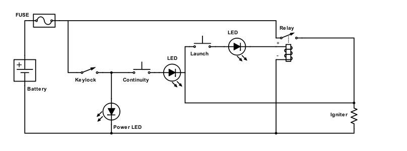
TIvrhQq.png


Thoughts on this schematic?

Battery I'm looking at is a Gens Ace 11.1V 45C 1000mAh LiPo
30A thermal fuse
Keylock switch.
12V 12mA Red LEDs.
40A auto relay

~50ft run of 14Gauge wire to the igniter.
 
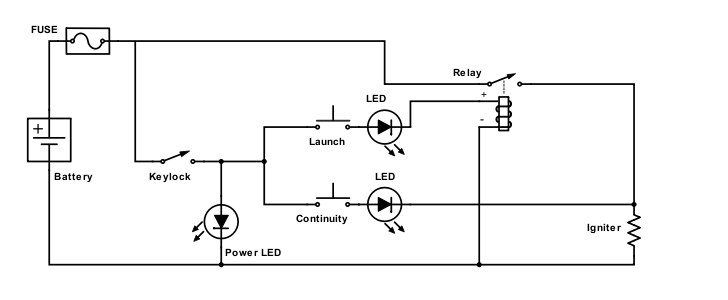
eWtzmDh.png


Thoughts on this schematic?

Battery I'm looking at is a Gens Ace 11.1V 45C 1000mAh LiPo
30A thermal fuse
Keylock switch.
12V 12mA Red LEDs.
40A auto relay

~50ft run of 14Gauge wire to the igniter.

You'll need a 1K resistor in series with your power and continuity LEDs. For the launch LED, add a series 1K resistor, and put both the led and resistor in parallel with the relay coil. That should do it. But those LEDs may be hard to see in sunlight. I'll look at some alternatives after dinner.
 
You'll need a 1K resistor in series with your power and continuity LEDs. For the launch LED, add a series 1K resistor, and put both the led and resistor in parallel with the relay coil. That should do it. But those LEDs may be hard to see in sunlight. I'll look at some alternatives after dinner.

Sorry - I changed the drawing seconds before you replied. I want both continuity and launch buttons to be pushed simultaneously as a 'safety feature'.

Also, these are the LEDs I was thinking https://www.digikey.ca/scripts/DkSearch/dksus.dll?Detail&itemSeq=262272619&uq=636633843037841118

They're listed as internally resisted so figured I'd be good to go.
 
The fuse is mostly redundant as just the wire resistance will limit short circuit current to no more than 47A. (with 12V input) Add in contact resistance and internal battery resistance and it will be less.

The LED will die, perhaps spectacularly, if it provides enough current to pull in that relay. But since it appears to have an internal current limiting resistor, the LED will light but the relay will stay closed.

In other words - I should be looking at lighted switches instead?
 
Or is it just a matter or wiring them up differently...like so:

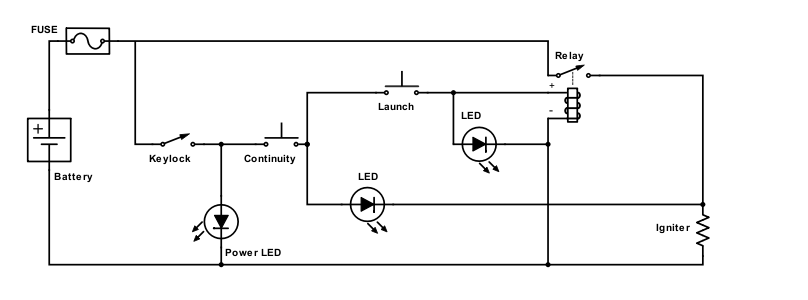
o9V0T0w.png

That looks better, since the LEDs have internal resistors. Also, with the launch LED in parallel with the relay, the relay will energize.

I tried to look at the LED on digikey, but the link doesn't work for me. Do you have a part number? My main concern is whether they are bright enough to be visible in daylight.

LTH5MM12VFR4100

Also, side question - will I be okay using a 1A rated keylock switch - or should I go with something heftier? with the 3 LEDs and relay I get ~180mA.
 
Splitting hairs. Sure, it is the heat generated by the igniter that lights the pyrotechnic tip (if present) and ultimately the motor. But power is directly proportional to both voltage and amperage. If you don't have enough volts or amps you won't have enough power. Since batteries are generally rated based on their voltage and current delivery capability, it is much easier to simply talk volts and amps... which results in power, which results in heat, which results in fire if enough heat is present. The more amps you present, the faster you have fire.
Actually you were right in the first place; power is proportional to the square of current. Voltage is necessary to drive current but current is the overriding factor. Current squared times resistance is power.
 
Move the thermal breaker to the high-current igniter side of the circuit. That way you can still get continuity and test the relay.
Dave's suggestion about using the wiring and contact resistance to limit current is not recommended. I've seen wiring melt and relays welded by shorted igniter leads. I've included the auto reset thermal breaker in many launch controllers over the years (and in industrial products I've designed). It doesn't kick out for igniters but protect things if there's a dead short of a few seconds.
 
Actually you were right in the first place; power is proportional to the square of current. Voltage is necessary to drive current but current is the overriding factor. Current squared times resistance is power.

True. I was just using a different slice of Ohms Law: P=IE. Of course I is dependant on R, and so P=I^2 R is equally true. And for the sake of completeness, P=V^2/R.
 
LTH5MM12VFR4100

Also, side question - will I be okay using a 1A rated keylock switch - or should I go with something heftier? with the 3 LEDs and relay I get ~180mA.

Ok, that led should be plenty bright.

In regards to the keylock, it is sufficient if you use it as shown in the schematic. However, looking at your schematic, you may want to consider moving it in line with the fuse so that it isolates the high current side also. (Which would require a higher current keylock) I'm thinking of a scenario where the relay contacts stick, but the fuse does not open because the igniter burned and opened the circuit. In such a circumstance, the igniter leads would be live with 12 volts when you hook up your next igniter even though the key is off/removed. SURPRISE! :shock:
 
Ok, that led should be plenty bright.

In regards to the keylock, it is sufficient if you use it as shown in the schematic. However, looking at your schematic, you may want to consider moving it in line with the fuse so that it isolates the high current side also. (Which would require a higher current keylock) I'm thinking of a scenario where the relay contacts stick, but the fuse does not open because the igniter burned and opened the circuit. In such a circumstance, the igniter leads would be live with 12 volts when you hook up your next igniter even though the key is off/removed. SUPRISE!

Great.

I think it would be quite odd for the relay to break down before the fuse pops, given the relay is rated at 40A and the fuse 30A.

I suppose that could fall under 'mechanical failure' as opposed to circuit overload - something that rarely happens but can happen. In which case an automotive ignition switch would do that trick..
 
Sure, it is a failure mode that may never happen. But it's not impossible. A cheaper alternative would be to wire a 12V piezoelectric buzzer near the igniter end of the wire. That way it would scream at you if the igniter leads were live. However, I'm not sure if that would cause a false pass of a continuity check... I may need to test this.
 
Back
Top