Madcow Formula 98 - L2 cert build

The Rocketry Forum

Help Support The Rocketry Forum:

This site may earn a commission from merchant affiliate links, including eBay, Amazon, and others.

Rockethound

Infinity is in our minds
Joined
Mar 9, 2018
Messages
200
Reaction score
4
Location
Sacramento, CA
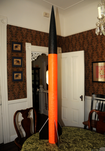
LDRS is a special event, and this year it's as close to my house as it can get. This is a special opportunity to get a Tripoli L2, which opens up EX motors as well, at Tripoli's premier event. I couldn't resist and ordered a Madcow Formula 98 last Thursday. I called to hopefully arrange Priority Mail shipment, and George made sure the package shipped the same day. I received it Saturday; thanks Madcow!

DSC_6713.jpg

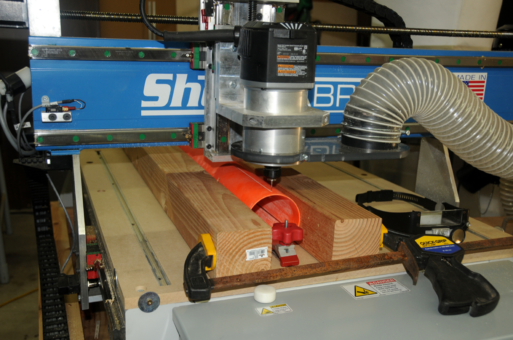
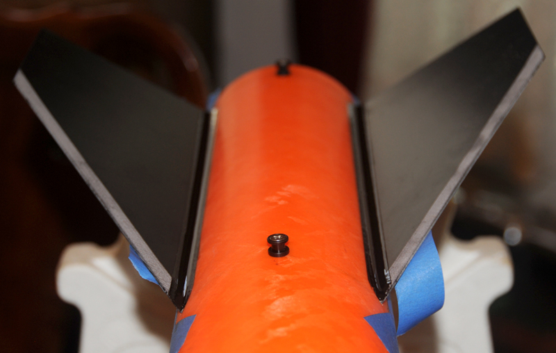
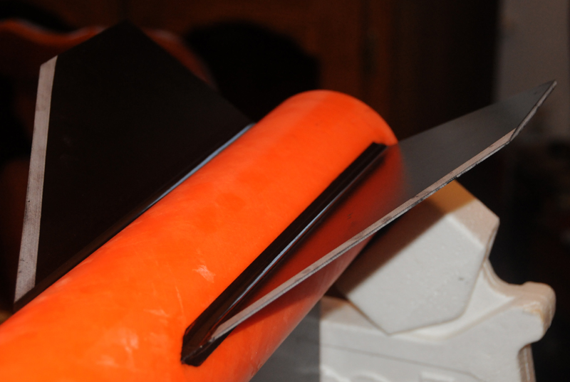
This isn't a test-fit photo - that didn't go very well. The fins didn't fit, and it wasn't something to sand off. The fins are .130" thick and the slots are .112" wide. I have a shop, so I knew this was not what they intended - 0.018" is a huge mistake in CNC.

I called Madcow this morning and spoke with Kevin. He got me a 12" section of 54mm orange G12 for a tracker bay, then we talked about the slots. He reacted rather nonchalantly, considering what I was telling him. I rechecked on the phone at his request, yep, 0.112" width. He pulled down a fincan and measured it - 0.130", just what it should be.

He apologized for the problem quite earnestly, explaining that Madcow had brought slotting in-house because of this kind of thing. They were working with a vendor that made numerous mistakes, some almost comical expect for the poor customer receiving them. He saw the Priority Mail, set up a new fincan which has already been put into the USPS system for Priority Mail shipment, and threw in the 12" G12, all shipping at their cost. He also sent me a return setup, as it looks like they could recut the slots on their 4-axis machine and get them right. Madcow is a very impressive company.

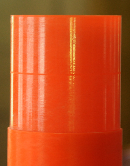
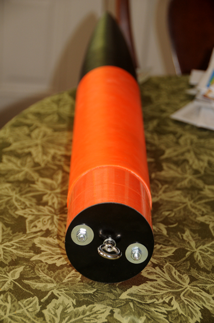
The Formula is very impressive, too, and there is a lot of progress. The shoulder is glued into the NC with Rocketpoxy, resulting a perfect joint against the payload bay. Very good machining everywhere except those slots.

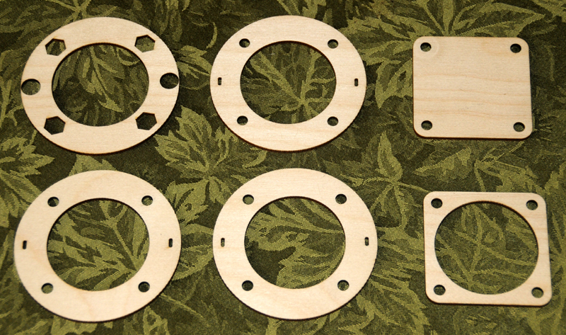
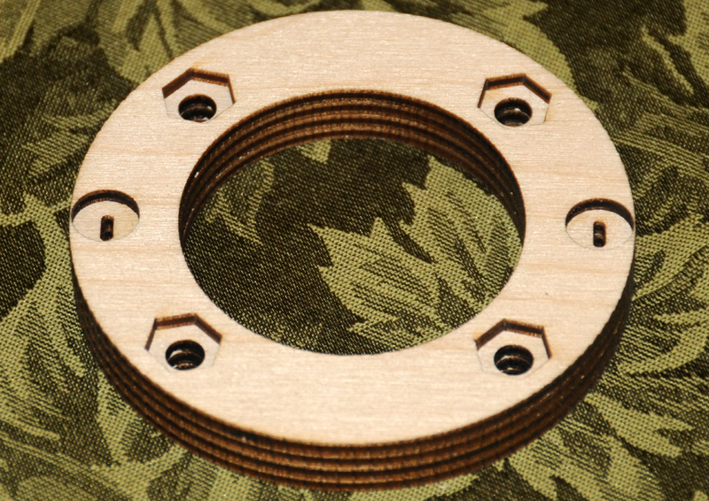
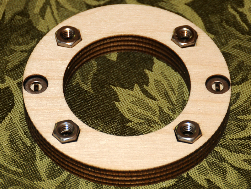
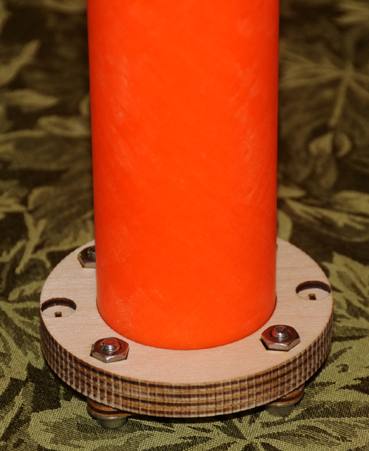
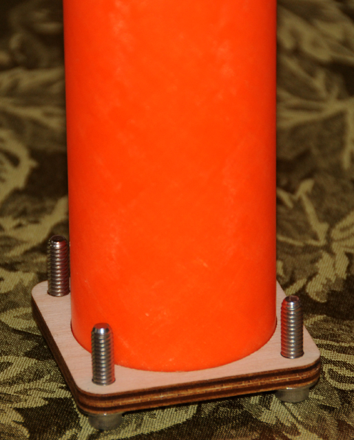
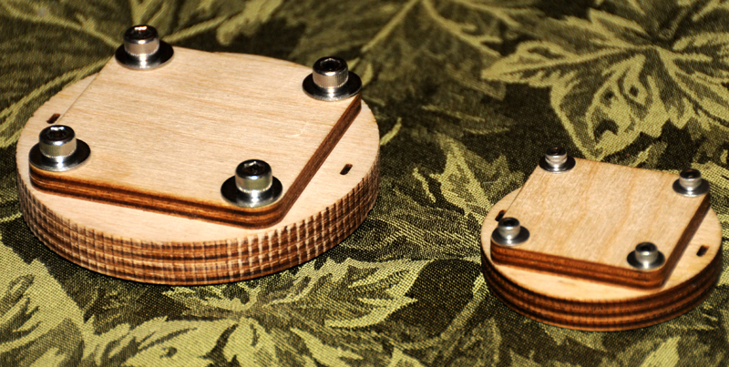
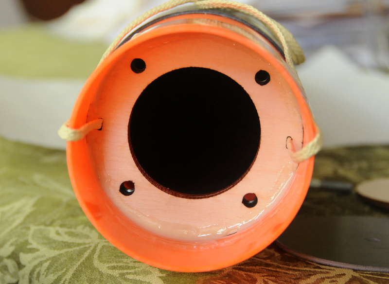
The avbay bulkheads and all-thread is built. It's nice and a bit odd to have CNC in the garage. It comes into play often. Here is a jig for making the avbay bulkheads.

DSC_6695.jpg

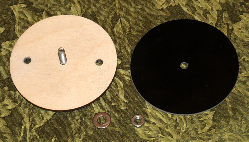
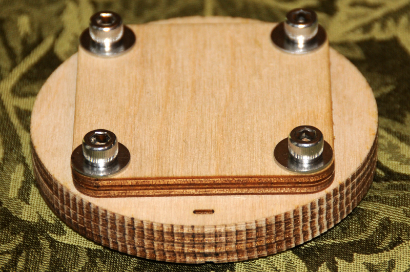
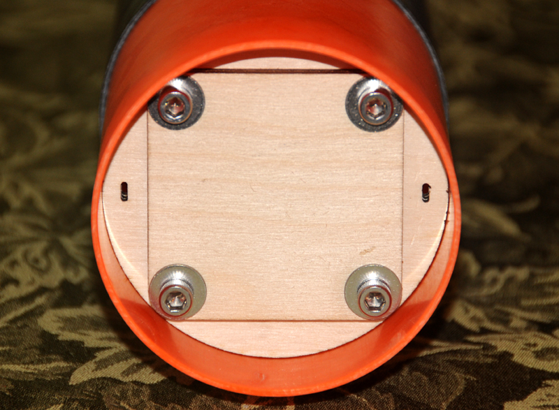
A sample bulkhead is next to it. Each bulkhead pair was epoxied together with their centers aligned. Then both bulkheads and the jig were bolted in a stack at the center. The first hole was drilled through both bulkheads, a second alignment bolt inserted, and the second hole drilled. Everything aligns exactly.

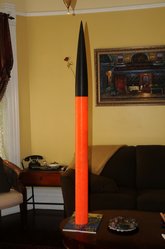
I chose to go without the switch band and glue the avbay coupler into the payload bay. It still extends 4" into the fincan as it would have with the switch band, but now it extends 5" into the payload bay. That can be made up at the other end in the nose cone, which will come in the next post.
 
The nose cone on the Formula 98 is huge! 22.25" long 5:1 Von Karmen, it has lots of space that I didn't want to lose. The payload bay is relatively small, and I know this rocket will need a tracker someday soon. I built a new attachment system for the NC harness with the laser cutter and 3mm Baltic birch aircraft plywood. Here are the components of the attachment point and tracker mount, as well as the tracker carrier base.

DSC_6694.jpg

The upper-left ring is topmost in the stack. Six hex slots nest SS nuts that will be epoxied into place, probably using JB because it's good with steel. The two square pieces are the tracker carrier base. The oval-shaped slots left and right are for the 1/4" Kevlar tubing. After gluing the stack with Titebond II, it looked like this.

DSC_6698.jpg

This mount is far different than the typical bulkhead and eyebolt approach, which is very heavy, all told. The G10 bulkhead with the kit weighs 34g, to which 50-60g of eyebolt hardware will be added... almost 100g.

DSC_6700.jpg

The mount and hardware shown here weigh 48g total. The nuts are there to hold in the tracker carrier. There is a #10 washer in each of the other two holes, which align with the oval-shaped slots.

The Kevlar will be threaded through each of the slots and tied into a double-overhand knot with T-88 epoxy tied into it. These knots will be pressed and shaped into the cavities as the epoxy cures to flatten them against the washers and provide some seal to the slots. Then another batch of epoxy will be poured into each cavity, filling them both to the brim.

To me, this seems stronger than using an eyebolt centered in a bulkhead, and it opens up the nosecone for future uses. Here is the how the tracker carrier mounts on the mount.

DSC_6701.jpg

Flipped over, with a 54" body tube that will hold the tracker.

DSC_6706.jpg

Only the tracker carrier.

DSC_6710.jpg

The assembly inserted into the NC shoulder coupler.

DSC_6705.jpg

I'm throwing this idea out for critique. I believe it will be stronger than the eyebolt/bulkhead approach and lighter as well. The #10 washers help distribute the force so the knot doesn't punch through the 3 3mm layers of Baltic birch ply. I built the same kind of thing, scaled down, for the Darkstar 2.6.

If anyone sees a problem here, please let me know. There's no epoxy showing in the bottom photo!

Thanks... Randy
 
I have the F98 & really like it but my only complaint is you have a limited number of motors you can fit in it due to booster length. Can’t fit any 6 grain motors in it & 5 grains are snug.
 
It's not uncommon at for fin slots to be tight on FG kits no matter who the maker is. A Dremal tool opens the slot up in seconds
 
I love the Cnc plywood pieces. However I would mount the tracker sled directly to the tracker base and just get rid of the FG tube.
 
I have the F98 & really like it but my only complaint is you have a limited number of motors you can fit in it due to booster length. Can’t fit any 6 grain motors in it & 5 grains are snug.

Mine takes 6XL's
2" switch band on the E-bay coupler with a drop stepped bottom bulk plate

Very nice work on the Tracker bay
 
It's not uncommon at for fin slots to be tight on FG kits no matter who the maker is.

Minor variances occur, sure. But 0.018" out of 0.130" is almost 15% wrong. Always feel OK calling the mfr. Kevin knew right away what was wrong and even told me what had happened. He was courteous, apologetic and pro-active. As long as you recognize a real difference vs. a manufacturing tolerance, they'll take care of you.

I have the F98 & really like it but my only complaint is you have a limited number of motors you can fit in it due to booster length.

Absolutely true. For an L2 cert bird, though, it feels OK. I realized that this is rocket #3 of NNN and I don't have to optimize everything. I can build it strong and solid in three weeks and get L2 at LDRS, which for me is very cool. Within its motor envelope it has nice performance numbers, though. This is why it has a tracker bay from ground zero, so I can cert low then fly high using the space in the nose cone.


Does anyone think this design could be a problem? I don't want to believe my own BS, so to speak.
 
However I would mount the tracker sled directly to the tracker base and just get rid of the FG tube.

Thanks - I don't want to waste weight. I was concerned about cantilever forces during landing. The photo is with the motor mount tube on-hand. I ordered a new BT with the fincan today, which I planned cut down to 4-6" or so. Does that feel more appropriate?
 
This is what I had in mind. I used an angle bracket to mount the tracker sled directly to the NC bulkhead. No need for a tracker tube.

tracker.jpg
 
Hawk... good thoughts... thank you for the image. Images are worth far over 1,000 words in modern English.

Please assume I respect your input but have questions. Has your mount survived enough abuse to be proven? One of the mfrs, maybe Egg, offers a unit with a choice between your 1/2 wave Tx antenna as well as a 1/4 wave wire antenna. Others who have used the one in your photo found that it could break at the antenna/lead joint enough to justify offering both options. I felt that using your style antenna required additional mechanical support.

The second question is about investment. Before posting this, I thought the tube provided good protection to the tracker and was "best practice" engineering. If anyone's results tell me I'm over-engineering, yours is a very attractive alternative. OTOH, if the tube provides a worthwhile increase in protection of the $250+ tracker, 40-60-g extra weight might be justified in an 8 lb rocket.

Nice mount. Thanks very much for posting your alternative! I believe we are all trying to do our best and share our learning.
 
On the left is the 4" setup for the Formula 98 using 1/4 x 20 bolts. On the right, the Darkstar 2.6" setup using 6-32 bolts. It seems that a 3" setup using #8 or #10 could be feasible.


DSC_6717.jpg

The 4" version has been sanded for better glue contact with the NC shoulder tube.
 
It's not uncommon at for fin slots to be tight on FG kits no matter who the maker is. A Dremal tool opens the slot up in seconds
Not uncommon for filiment-wound tubes' slots to be narrow unless you make a few more passes to open the slot. It's because it's under a lot of pressure pulling the surface inward. If the slot is too narrow from end to end either his bit is worn or just the wrong size.
Also once they are slotted, a normally snug cr will be difficult to insert in the tube because the release of the tension. Once you force the cr in there it goes back to its original shape.
 
Please assume I respect your input but have questions. Has your mount survived enough abuse to be proven? One of the mfrs, maybe Egg, offers a unit with a choice between your 1/2 wave Tx antenna as well as a 1/4 wave wire antenna. Others who have used the one in your photo found that it could break at the antenna/lead joint enough to justify offering both options. I felt that using your style antenna required additional mechanical support.

I've flown that antenna in a Formula 75 a few times and haven't had issues with it. Of course that doesn't mean it couldn't break off next time. One option would be to extend the plywood sled so the antenna is supported by the sled and then wire tire the antenna to the sled.

The mini-egg finders have much smaller antennas and they are attached with a bolt, not just solder. Here's a picture of my other two egg finders; an original and a mini. Both of them are mounted in sleds from Lab Rat Rocketry. I really like these sleds and they are designed so that you can mount them to any 38mm or greater nose cone bulk plate using a 1/4" bolt.

Tracker 2.jpg
 
The Kevlar will be threaded through each of the slots and tied into a double-overhand knot with T-88 epoxy tied into it. These knots will be pressed and shaped into the cavities as the epoxy cures to flatten them against the washers and provide some seal to the slots. Then another batch of epoxy will be poured into each cavity, filling them both to the brim.

If possible, avoid getting epoxy on the harness. This will weaken it. The way it works is that the rigid epoxy will result in stress concentrations because the epoxied fibers can't align themselves anymore in a way that evenly distributes the load among the fibers. This increases the risk that only a few fibers carry most of the load, causing them to break at loads that are much lower than the harness could carry otherwise. As soon as those fibers break, some other fibers will become the most stressed ones.

On a side note: This also applies to stranded wire when it gets soldered. This is best avoided too (crimp connections are better) or at least precautions must be taken to carefully relief the joint from strain and vibrations.

Reinhard
 
I've flown that antenna in a Formula 75 a few times and haven't had issues with it. Of course that doesn't mean it couldn't break off next time. One option would be to extend the plywood sled so the antenna is supported by the sled and then wire tire the antenna to the sled.

That's a good reason to be confident. I learned about the breakage problem on one of the tracker mfrs' sites, where the buyer may choose the style of antenna they prefer. I'll be using the eggfinder with the bolted wire; Cris is a fine man with great products.

Your photo shows two of the 3D printed parts that were the inspiration for the tubes. But the plywood sled is definitely lightweight and easily cut on the laser. I appreciate your suggestion - and seeing that you have different styles for different applications.

Not uncommon for filiment-wound tubes' slots to be narrow unless you make a few more passes to open the slot.

I'm building a Darkstar 2.6 in parallel. Its fincan slots are spot-on, maybe a thou variance end to end, but certainly not off by 15% of the width. The reason I wrote this is so people don't blindly proceed with a tough task and get rough-hewn results when the fact is that rocket mfrs are just people like us, in small shops, and mistakes can happen. Call and ask if your caliper says more than 0.005" difference between fin thickness and slot width, or some such number, as their machines can easily hold 0.002" tolerance and usually 0.001".

If the slot is too narrow from end to end either his bit is worn or just the wrong size.

I have a 3 axis CNC router that holds 0.001" 90% of the time. If it was 4-axis I could have routed the slots properly myself. If the bit was worn, the cut would be fuzzy in a very characteristic way (similar to drilling holes through FG). There are no 0.130" end mills. This slot was probably intended to be a 0.130" mortise cut with a 1/8" or 1/16" end mill, but was set up wrong in the CAM program. The vendor that made the fincan is no longer making parts for Madcow.

I wasn't going to tell the story, but the vendor did very odd things. Last year Madcow had a Nike Apache sale. There was such demand they opened up the build quantity and let the vendor drop-ship to the customer. This four-fin rocket arrived to some customers with three fins at 120 degrees and the fourth between two of the others. Can you imagine opening that package? Things can go wrong for everyone! What's most important is the gracious treatment Madcow gave me, and Kevin assuring me this wasn't made right and doesn't represent their typical work.
 
If possible, avoid getting epoxy on the harness. This will weaken it. The way it works is that the rigid epoxy will result in stress concentrations because the epoxied fibers can't align themselves anymore in a way that evenly distributes the load among the fibers.

Reinhard, please help with this important consideration. I read here in TRF the cautions about epoxy and Kevlar and intended this design to avoid the problems. From what I read earlier, it seemed like this was important only if the Kevlar was expected to flex. My goal was that no epoxy get below the cavity - and if some did, the Kevlar would not be flexing within the slots. I tried to follow the same design principles people use when making a fincan Y harness glued to the MM.

The knot need not be epoxied, and could be a different style knot. Or maybe it will work as is, given how I intended to build it. As Ross Perot once said, "If you have a good idea, I'm all ears!" Do the details here make it feel safe to you?

Thank you very much for your input! This is exactly why I started the thread.
 
I read here in TRF the cautions about epoxy and Kevlar and intended this design to avoid the problems. From what I read earlier, it seemed like this was important only if the Kevlar was expected to flex. My goal was that no epoxy get below the cavity - and if some did, the Kevlar would not be flexing within the slots. I tried to follow the same design principles people use when making a fincan Y harness glued to the MM.

You're right in that flexing is probably the worst case scenario. If applying load mostly means more stress, but no significant change in direction, like in your Y harness on the MM example, the effect is much smaller. Besides, if Crazy Jim and other experienced flyers have been doing it for years, it can be assumed to be reliably even if it is "technically" not the best way.
A generic way to think about it is: What kind of loads can be applied and how does the fiber react then (elongate, slip, bend)? Will the presence of epoxy interfere with that? If the answer to the later question is yes, there is a risk of the Kevlar line/strap/tubing getting weakened.

The knot need not be epoxied, and could be a different style knot. Or maybe it will work as is, given how I intended to build it. As Ross Perot once said, "If you have a good idea, I'm all ears!" Do the details here make it feel safe to you?
If your Kevlar is strong enough (i.e. nominally significantly stronger than needed for the expected loads= and it is possible to visually inspect the transition area between epoxy covered and free Kevlar, regular inspections should be enough.
If the load direction is known in advance, the Kevlar can be slightly preloaded in the correct direction while the epoxy hardens. When flight loads become applied later, the fibers are already oriented correctly and flexing will be minimized.
Chris Atteberys approach works also well to connect the Kevlar without weakening it: https://www.rocketryforum.com/showthread.php?137544-Wildman-Blackhawk-75&p=1720934#post1720934
Finally, if glue is desired for sealing purposes or some other reasons, it helps to use a somewhat soft and flexible glue (e.g. silicone based).

Reinhard
 
How ironic - the way Chris did it is the way I hoped Teddy (OneBadHawk) could do it. He knows how to build safe loops, so I wrote him this morning. He couldn't meet the time line, so I'm back to considering your point and engineering through it.

Fact is, CJ and lots of others make very similar Y harnesses. Regardless, you are right about fiber stress, so I came up with a different knot with more layers that had one of the tag ends coming out of the center of the knot. The tightened knot was centered in the cavity and pulled down tightly, then the remaining tag end looped around the outside of it. With tension on the shock cord, I molded some Rocketpoxy over the Kevlar mass making a flattened, igloo-shaped dome. It's really only to keep the Kevlar oriented so the stress is spread widely among the fibers, so right now it is curing with 35 lbs of weight on one of the two connections.

The other side will be put together shortly, then I'll post some pix of the process.

If the load direction is known in advance, the Kevlar can be slightly preloaded in the correct direction while the epoxy hardens. When flight loads become applied later, the fibers are already oriented correctly and flexing will be minimized.

PS - this is what was done.
 
This is how the knot is aligned and pulled into the cavity. Then the tag end is tucked in the empty ring around the knot.

DSC_6721.jpg

The second Rocketpoxy igloo is made and the first has been trimmed and smoothed. I'll keep the edges clean over the next few hours, maybe shape the Rocketpoxy after bearing load for a while.

DSC_6722.jpg

 
The next morning. The Rocketpoxy and JB Weld are almost fully cured after spending the night with 50 lbs on the harness to preposition the Kevlar. The 4 SS nuts had their sides roughed up with 80 grit sandpaper, then JB was coated on the sides of the nut cavities. Using four longer, shouldered zinc bolts for extra centering precision, each SS nut was pulled into place and tightened down. There was no need for JB under the nuts, as the nuts' sanded sides will be held by the fierce grip of JB; the bolts backed out easily.

This thing is *strong*! Resting on top of two hockey sticks a half-inch apart, quick-linked to a Kevlar loop around a 2x4 with one end on the garage floor, it supported my 185 lbs standing on the 2x4 very near the harness. The NC will be about 850g without tracker, so maybe 950 with tracker or about 2.1 pounds. Another thread says a good guideline for recovery components and shock cord is 75x the weight at the end being considered. That would be ~160 lbs, so this test passed.

The mount weighs 51g including nuts, epoxy and Kevlar - half the weight of a closed G10 bulkplate with eyebolt, washers and nut. It has no perceptible flex.

It will be mounted at least an inch into the NC, maybe two, to open up the volume in the payload bay that got infringed by the avbay being glued 5" in with no switch band.

14 days to LDRS. On to the motor mount.

DSC_6726.jpg
 
Please stop. You're having too much fun!

Oh. Thank you for warning me.

My name is Randy. I am a Rocket-holic...


The time came. The mount passed its tests. It needed to be glued into place.

DSC_6728.jpg

I screw in the tracker carrier now and then, and there is clearance. Denatured alcohol washes off what epoxy is picked up. When this cures, I'll flip the harness inside, then fillet between the harness and the coupler and thicken the stress-bearing region.

So here's one that I decided is a manufacturing tolerance, but it's pretty large. This picture shows two strips of Ace packing tape wrapped around the coupler.

DSC_6729.jpg

It's 3 mil tape so the diameter is off by 0.006", but it is workable. The tape is just thick enough to make a near-perfect nest within both BTs. Thank goodness for small favors. I made six 1/2" patches of tape, taped them onto the coupler at 120 degrees near each end of the half to be glued, which let them center the coupler within the payload bay as the Rocketpoxy gripped the 98% of non-taped FG. Now the avbay coupler is centered throughout and the payload bay and fincan are well-aligned and completely flush.

It will be interesting to compare the fit of this fincan to the one that arrives today. And I wonder how the tape will react to ejection. Is Kapton in my future?
 
The new fincan arrived, but surprisingly it had exactly the same width fin slots. After talking to Mike, the owner of Madcow, it was clear that to get the precision I want on this particular set of parts, I'd have to do it myself. I took the vacuum table off the CNC router and used hold-downs in T slots to align and stabilize the fincan.

DSC_6748.jpg

It was clear that the G12 was flexible enough to chatter if the RPMs got in sync with the material, so 4x4s are clamped on each end just hard enough to make the fincan bow upward a tiny amount. Using a 1/16" down-cut end mill from Onsrud, I cut outward from the centerline on each side until both sides of a slot were exactly parallel and axially aligned.

The slot widening continued at 0.003" per side until it felt close; then the step was reduced to 0.001" on alternating sides. On each fin, this 0.001" step was enough to cause an obvious change at some point: the fin went in!

DSC_6760.jpg

They are all aligned to the rocket's central axis, and naturally align themselves radially very close to what the fin guide will ensure. Finally, the fit test works. The forward CR of the motor mount is now curing and the build continues. Some laser-cut fin guides are coming up soon.
 
The fin guides were laser cut at 120 degree spacing and 0.132" fin thickness. All the fins line up, which is a great relief since the CNC router could have cut them at a slight angle if the fincan wasn't set up properly. The mandatory MM photo is here. It's cured and ready for fins to be glued into place. The motor retainer and bottom CR are just there for measurement, not glued.

DSC_6769.jpg
 
The fins were glued to the MM with the root edges buttered with Rocketpoxy (RP) and cured in the fin alignment guide. Even with just one buttering, they already feel rock solid.

DSC_6770.jpg

I cut six 10.7" x 0.20" sticks to build the internal fillets. Two corner faces were thickly buttered with RP and inserted through the back.

DSC_6777.jpg

The RP flowed a bit outside the sticks and very nearly fills the small gap between fins and sticks from tube curvature. RP is incredible epoxy... very nice to work with throughout its cure cycle, very predictable, and shockingly strong.

DSC_6780.jpg

All that remains in filleting the fins. The recovery equipment is assembled and attached to the avbay.

For the L2 flight the rocket will be flown with motor ejection.

DSC_6738.jpg

A nice coincidence occurred. The Y harness is just the right length to butterfly into the top of the avbay...


DSC_6741.jpg

...and when the avbay is assembled, the NC can only move up about 1/2". It doesn't need to be screwed into place for this phase of the rocket's life.

The chute will be in the fincan, which is fine for a sim height of 2400' on a J425 flying at TCC. Once the L2 is over, the rocket will get equipped with DD, tracker and other improvements... during the long, hot summer when open launch sites are far from home.
 
Rail buttons are on, so it was time to do the fillets. Rocketpoxy is an amazing adhesive. From structural joints to fillets, it is predictable and strong.

DSC_6787.jpg

These are the first two fillets, pulled with 1/2" copper pipe. I followed a suggestion by Steve Shannon in another thread on fillets and poured a small amount of RP into the joints just after mixing to penetrate and bond the fin-BT internal surfaces. Following the advice of Eric and from CJ's threads, I then let the bubbles rise and the RP thicken for about 20 minutes.

That was just about right. 25 minutes maybe could have been better, as three bubbles surfaced in the fillets. They were pricked with toothpicks and the RP smoothed itself. I'm so pleased with the results, I will be incorporating RP into my R/C planes in certain locations.

For anyone with black fins, I found that using a Sharpie on the pipe was fine on the orange FG but not visible on the fins. I tried again using carbon paper and voila, the lines were visible on both BT and fins. Carbon paper is easier for me to use than Sharpie-on-the-tool, as the lines go from end to end without interruption - as well as their visibility on black G10.
 
This is the last pair of fillets.

DSC_6789.jpg

Rocketpoxy is amazing. Every fillet came out the same - very nearly perfect. With 25 minutes cure time before application, no bubbles appeared in the fillets. How can a product work so well? As someone who appreciates physics, it's as though the viscosity and surface tension work together to make a minimum area surface. Even after popping a bubble (early enough), surface imperfections disappear.

Next in line is finding the right ejection charge. Then it will be ready for L2 this Wednesday or so, depending on weather and schedules. In another thread, I discussed how the swivels needed to be smoothed. That is going well, and I need to update the other thread.
 
Back
Top