Is 24 gauge wire OK for dual deploy ejection charges?

The Rocketry Forum

Help Support The Rocketry Forum:

This site may earn a commission from merchant affiliate links, including eBay, Amazon, and others.

Zeus-cat

Well-Known Member
Joined
Mar 14, 2009
Messages
4,991
Reaction score
1,455
I am building two avionics bays for two dual deploy rockets. One is 1.5 inches in diameter and the other is 29mm in diameter. Obviously size of components is critical. I have some twisted pair telephone wire. Can I use that for the wires from the altimeter to the ejection charges?

The longest one will be about 18 to 20 inches. I would guess the wire is 24 gauge and it is solid, not stranded copper. Would this work, or is it too small?
 
24 should work, but heavier wire would be better. I usually wire rocket electronics with 22AWG at a minimum.

More importantly, stranded wire is MUCH better in applications subjected to shock and vibration.
 
24AWG solid should work OK, although you'll want to be careful with how you attach it (since it's solid). I've certainly used it many times quite successfully. That's pretty much what e-match leads are made of, so you definitely don't need any thicker to reliably fire an e-match.
 
I am building two avionics bays for two dual deploy rockets. One is 1.5 inches in diameter and the other is 29mm in diameter. Obviously size of components is critical. I have some twisted pair telephone wire. Can I use that for the wires from the altimeter to the ejection charges?

The longest one will be about 18 to 20 inches. I would guess the wire is 24 gauge and it is solid, not stranded copper. Would this work, or is it too small?

24 Gauge is more than enough, unless you're running 100 feet or something. A 9V battery has 2 Ohms of internal resistance. A couple feet of 24 gauge won't make a difference. Heavier wire is just more mechanical stress on the rest of your system and lower performance, so I think that 24 gauge wire is just right. .
 
Like they said above, electrically you're golden. But, if you tweak this thin solid conductor around too much you could potentially break it under the insulation without knowing it.

Take a small piece and bend it back an forth a couple dozen times and you'll see on your own what it can tolerate.
 
Like they said above, electrically you're golden. But, if you tweak this thin solid conductor around too much you could potentially break it under the insulation without knowing it.

Take a small piece and bend it back an forth a couple dozen times and you'll see on your own what it can tolerate.

I already thought about that Scott. I think I was trying to convince myself that I wouldn't launch these rockets enough to have that problem pop up. You guys are correct; it will work, but it is not the optimal solution. I'll head over to the mom and pop hardware store tomorrow that is 1 mile from my house and see if they have a better wire. I am not really hopeful to be honest.

I would really like to get the big one in the air this Tuesday as the winds are predicted to be only 1-2 mph in the evening. I start vacation on Saturday so that might be the only chance I get for three weeks. I built the thing over a year ago, but never wired it.

Thanks for the advice. I'll let you know how it goes and post some pics if they turn out.
 
I would really like to get the big one in the air this Tuesday as the winds are predicted to be only 1-2 mph in the evening. I start vacation on Saturday so that might be the only chance I get for three weeks. I built the thing over a year ago, but never wired it.

Do you have a local Radio Shack? If so, you can buy a spool of stranded speaker wire in either 22ga or 24ga at a reasonable price.

-Kevin
 
The solid wire will work. As pointed out by other posts, it's not the best solution.

I prefer the stranded wire for connections that are used repeatedly. Tin them for better results, this will keep stray strands at bay (say that five times fast).
 
Before I knew better, I built my first altimeter bay with solid wire. It worked just fine for more than 30 flights, without any particularly careful handling, until the rocket was finally lost.

I always build with stranded wire now, for exactly the reasons given, but I wouldn't scrap a solid-wire bay just because it has solid wire built into it. I suppose not all solid wire is the same, and a little hand-testing wouldn't be a bad idea, but in my experience, something else is likely to go wrong before the solid wire breaks.
 
I prefer the stranded wire for connections that are used repeatedly. Tin them for better results, this will keep stray strands at bay (say that five times fast).

Tinning stranded wire is specifically NOT recommended by the manufacturers of the clamp type terminal blocks found on altimeters and other devices.

Much discussion here:

https://www.rocketryplanet.com/forums/showthread.php?t=4731

Tinning the ends of stranded wire can result in a stress concentration point at the end of the wire, which when subjected to vibration, can cause fracture much the same as a solid conductor. And when clamped into a terminal block, the soft solder can "cold flow" under the clamping force, eventually resulting in a loose/intermittent connection.

Where stranded wires need to be repeatedly removed and installed, there are crimp-on pins available for the purpose.
 
Last edited:
Tinning the ends of stranded wire can result in a stress concentration point at the end of the wire, which when subjected to vibration, can cause fracture much the same as a solid conductor. And when clamped into a terminal block, the soft solder can "cold flow" under the clamping force, eventually resulting in a loose/intermittent connection.

Where stranded wires need to be repeatedly removed and installed, there are crimp-on pins available for the purpose.
Yes! I've learned that on the forums, and from personal experience. Ferrules are the way to go, rather than tinning, for clamping wires, such as in a Phoenix style connector.

I've also noticed, when soldering wires to connectors, to not let the solder wick up the wire very far. It makes stranded wire brittle and prone to breaking, just as Bob points out.

Doug

.
 
Oh, I'm surprised to read this (about tinning stranded wire).

Can you post a link to those crimp-on pins that you mentioned? I'm having a hard time picturing this.
 
Oh, are you still putting the stranded wire into the terminals on the altimeter, but terminating them with those pins? That makes sense, and seems like it'd make things easier. I do use similar terminals for some of my smaller electronics bays, on which the bulkhead is too small for screw terminals.

Thanks for the advice.
 
https://www.radioshack.com/product/index.jsp?productId=2103509

Most manufacturers of crimp-on terminal lugs have a similar product in their line. For better quality, I would recommend Panduit, AMP, or Thomas & Betts over anything from RadioShack...

The recommended T&B tool from Grainger is about $350. :y: I bet it's nice though! :)

So, assume we buy the Radio Shack crimper and terminals.

The average hobbyist will do a handful of those crimps in a year. Will they do a better job at crimping or at soldering giving the low level of practice, training, and quality of the "consumer" tool and terminals?

Will they be better at identifying a bad crimping joint or a bad solder joint?
 
If I have to use wire, I use 24 gauge solid wire, and tack it down with 5-minute epoxy. That lets me get it into tight spaces like this:

DSC00399.jpg


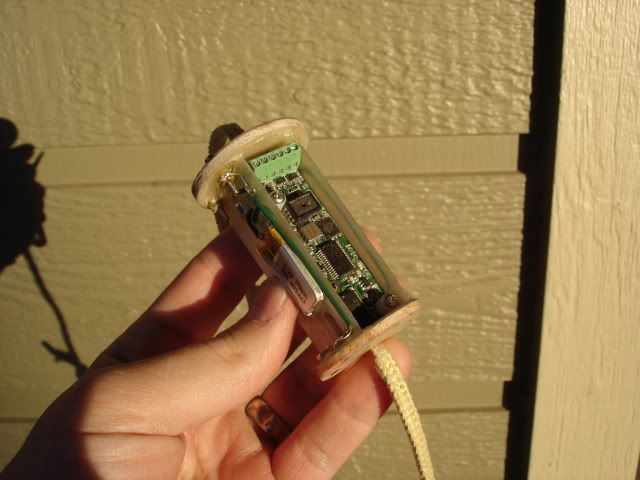
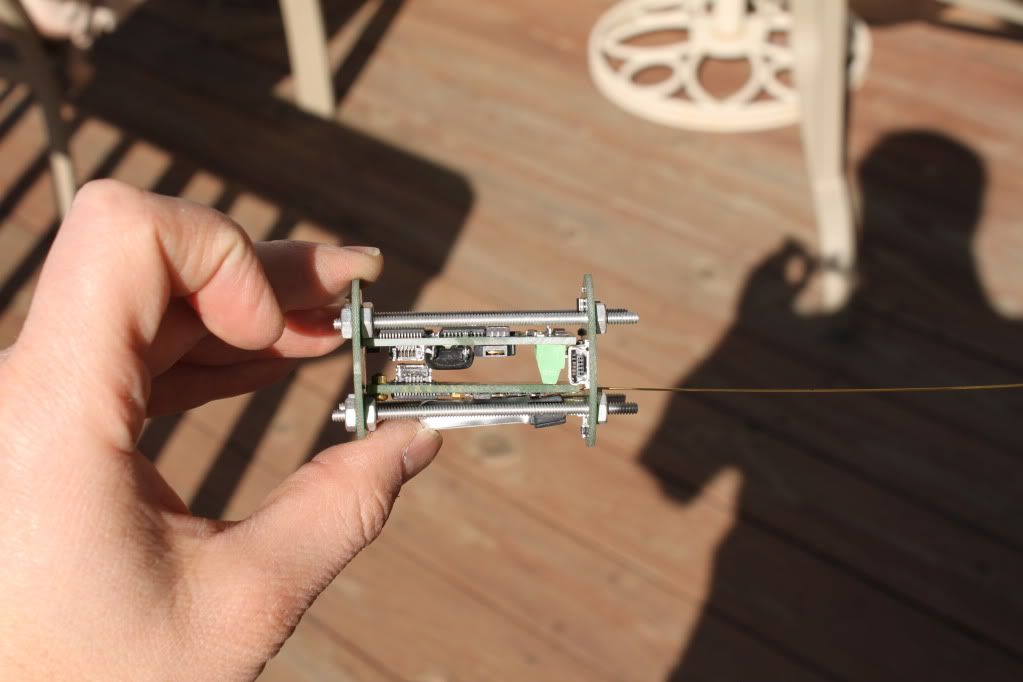
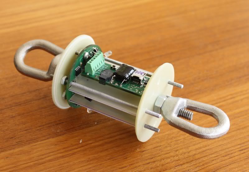
But recently, I've been going wire-free by making the av-bay bulkheads out of circuit boards that connect everything up:
IMG_1165.jpg

Custom 54mm version for a Balls project:
54mmav-baysmaller.jpg
 
But recently, I've been going wire-free by making the av-bay bulkheads out of circuit boards that connect everything up:

Okay, that cries out for a lot more photos and explanation. It looks really interesting.
 
The recommended T&B tool from Grainger is about $350. :y: I bet it's nice though! :)

Yeah, I never really understood that with the OEM tools. Panduit wants nearly $800 for theirs. :jaw:

For a reliable crimp, you need more than the cheap sheet metal pliers that typically comes with the terminal assortment from the auto parts store or whatever. But it doesn't need to be anywhere near the price of one of the OEM tools. The main feature to look for is a "controlled cycle" tool, which has a ratcheting mechanism to prevent over- or under-crimping.

Here's a basic ratcheting crimper for under $20:

https://www.amazon.com/dp/B0002KR9GQ/?tag=skimlinks_replacement-20


So, assume we buy the Radio Shack crimper and terminals.

The average hobbyist will do a handful of those crimps in a year. Will they do a better job at crimping or at soldering giving the low level of practice, training, and quality of the "consumer" tool and terminals?

Will they be better at identifying a bad crimping joint or a bad solder joint?

Good question. Proper tooling makes a bad crimp less likely, but the failure mode here isn't really due to "bad solder joints", but the essential unsuitability of solder-tinned wiring for use with clamp terminal blocks. Even wire tinned using a temperature-controlled dipping pot by a skilled operator would be subject to the same failure mode when used in this way.

All in all, I would still recommend the crimp pins if the wire will be inserted and removed regularly. If not, just strip the wire, twist the strands together, then clamp it down and go fly!
 
Last edited by a moderator:
What about potting the leads with silicone as they enter the terminal block?

I'd think that would keep things from moving around and breaking right at the base of the tinning.

-Kevin
 
Strain relieving the wires by any means (silicone, heatshrink, zip ties, etc.) would help address the breakage problem, with tinned stranded OR solid conductors. Use of standard RTV silicone around electronics introduces its own set of problems regarding corrosion. If you go this route, you should use an electronics grade silicone which doesn't release acetic acid during the cure.

Strain relief doesn't address the solder cold flow problem at all.
 
Last edited:
If not, just strip the wire, twist the strands together, then clamp it down and go fly!

I suspect this is the right thing to do when using a quality connector with a "leaf spring" mechanism.

The Radio Shack eurostyle connectors have the rotating screw face compressing the wire. This makes any twisting of bare wires a moot point.

The obvious answer is: stop using the Radio Shack eurostyle connectors! :bangpan:

Any suggestion for source of decent eurostyle connectors with leaf-spring connectors suitable for bulkhead use? I've found lots with one side for PCB mount but not any with screw terminals on two sides...

Thanks for this very interesting discussion, Bob!
Best wishes,
Will
 
I suspect this is the right thing to do when using a quality connector with a "leaf spring" mechanism.

The Radio Shack eurostyle connectors have the rotating screw face compressing the wire. This makes any twisting of bare wires a moot point.

The obvious answer is: stop using the Radio Shack eurostyle connectors! :bangpan:

That about sums it up. Radio Shack seems to source the cheapest crap they can get their hands on, and sells it at higher prices than the good stuff from a real electronics supplier. :confused:


Any suggestion for source of decent eurostyle connectors with leaf-spring connectors suitable for bulkhead use? I've found lots with one side for PCB mount but not any with screw terminals on two sides...

Newark stocks the Hylec line, which are as good as any I have seen. A 12 circuit double row block is available here, and can be cut to length as needed:

https://www.newark.com/hylec/pa44wp-f/wire-protector-terminal-block/dp/01M8455

If you want a real "bulkhead" type connection using euroblocks, get the PC mount type, solder and heatshrink the altimeter wires onto the PC terminals, then drill holes to pass the pins/wires through the bulkhead under the terminal block. For a gastight seal, you can backfill around the wires with epoxy from the inside of the bulkhead.

Personally, I don't care much for the terminal blocks (Eurostyle or standard), and I spend a couple extra bucks and go with 5-way binding posts for my ejection charge connections. No tools needed, and they give a more secure connection that you can visually inspect easily.
 
If you want a real "bulkhead" type connection using euroblocks, get the PC mount type, solder and heatshrink the altimeter wires onto the PC terminals, then drill holes to pass the pins/wires through the bulkhead under the terminal block. For a gastight seal, you can backfill around the wires with epoxy from the inside of the bulkhead.
But now we're soldering stranded wire again. Is it now OK because of the strain relief provided by the heatshrink tubing? What about your corrosion concerns?

Personally, I don't care much for the terminal blocks (Eurostyle or standard), and I spend a couple extra bucks and go with 5-way binding posts for my ejection charge connections. No tools needed, and they give a more secure connection that you can visually inspect easily.
Such as these https://www.newark.com/superior-electric/bp21bl/binding-post/dp/35F3003 ones?

Why are they "5 way"? :confused2:
 
Okay, that cries out for a lot more photos and explanation. It looks really interesting.

There's some more information here:
https://www.rocketryplanet.com/forums/showthread.php?t=5959

The basic idea is that the battery and altimeter are both connected directly to the bulkhead, and the bulkhead makes connections to the threaded rods, which also serve as deployment screw terminals. With 4 threaded rods, you have deployment terminals for 3 outputs that are all available from either end of the av-bay. The 4th channel is available at the end of the av-bay that has the altimeter.

The threaded rods also clamp the two bulkheads around a 2" long coupler. You would glue in the coupler into your airframe, typically at the aft end of your forward tube for a normal dual-deployment setup. Then before each flight you would prep the charge, shock cord and threaded rods at the forward end of the av-bay, then drop it through the forward tube. Then put on the rear bulkhead with the threaded rods and connect the charges and shock cord for the apogee deployment.
 
But now we're soldering stranded wire again. Is it now OK because of the strain relief provided by the heatshrink tubing? What about your corrosion concerns?

Strain relieved by the heatshrink and epoxy backfill. There is no problem with soldering stranded wire, as long as it isn't allowed to flex at the joint, same as any other wire.

Corrosion is a problem with some RTV silicones, not epoxies. The ones that give off a "vinegar odor" when uncured will corrode electrical connections.


Those will work just fine.

The "5-way" designation comes from the different ways to connect to the posts:

1.) Stripped wire through the crossdrilled hole and clamped.
2.) Phone tip through the crossdrilled hole and clamped.
3.) Alligator clip clamped into the end hole
4.) Banana plug inserted into end hole.
5.) Spade lug clamped under cap

Unofficially, there are at least 2 others:

6.) Alligator clip clamped onto threaded metal barrel.
7.) Stripped wire looped around barrel and clamped.

For ejection charge connections, you would most likely be using method 1 or 7.
 
Last edited:
Back
Top