Post weekend update.
Miraculously I found enough time to get what I wanted done for once.
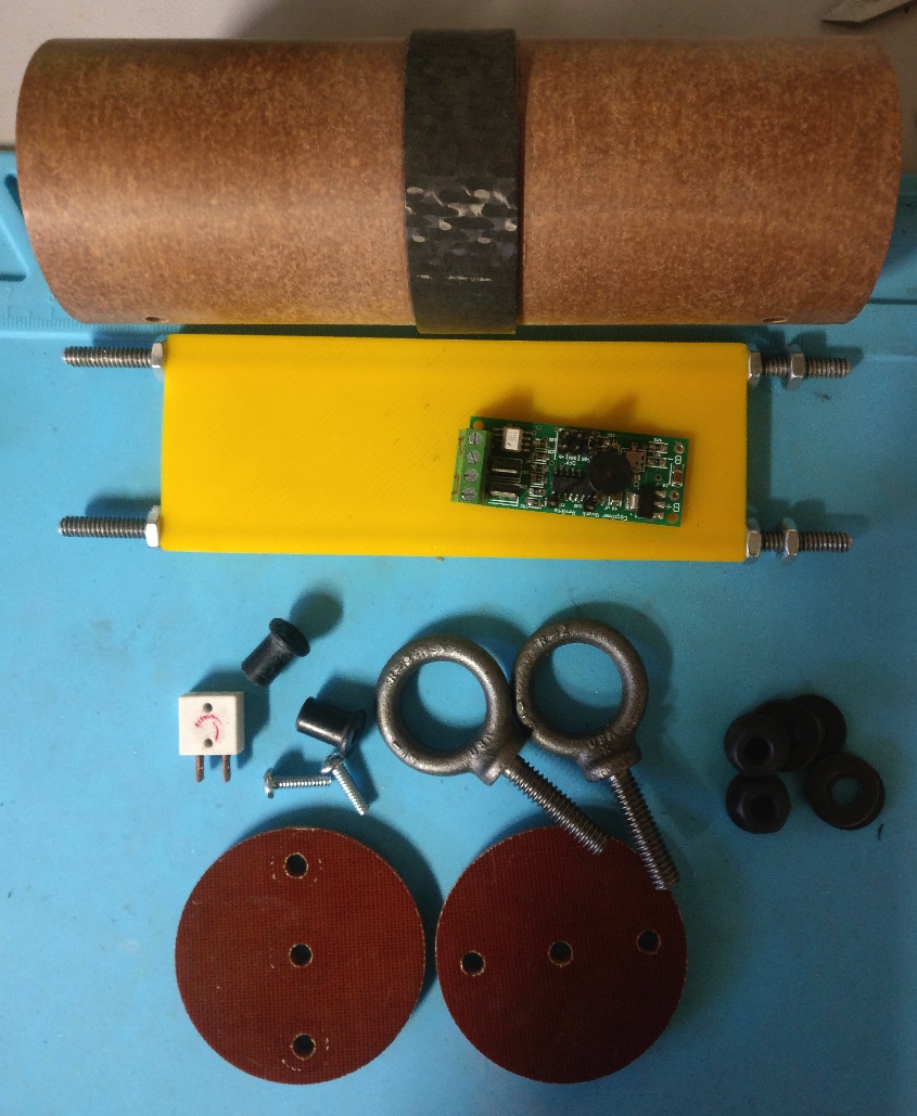
Gluing up the fincan.
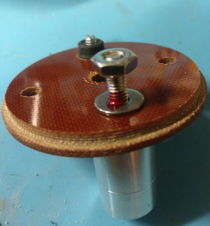
Step one was to mark the MMT where the fins would align, as I have an opportunity to lay down the epoxy bead for the root directly on the MMT, vs. on the fin and through the fin slot which is typically how I do this. I also took some 80 grit sand paper and scuffed up the retainer where it would sit under the tailcone. The plan is to glue the fins and the external part of the retainer where it meets the inside of the tailcone. This is also unique to this build.

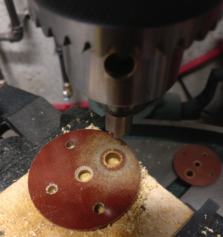
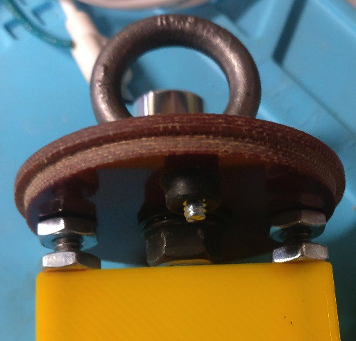
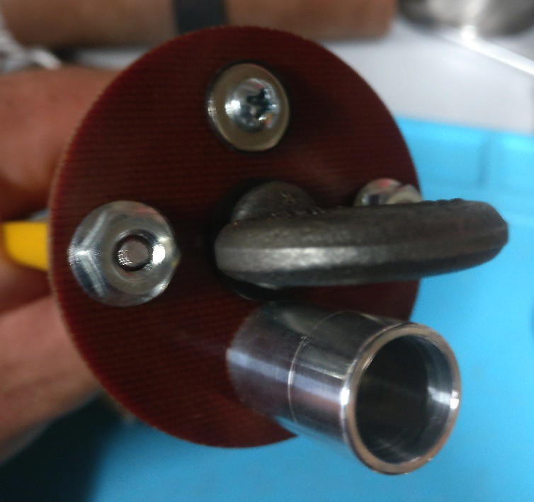
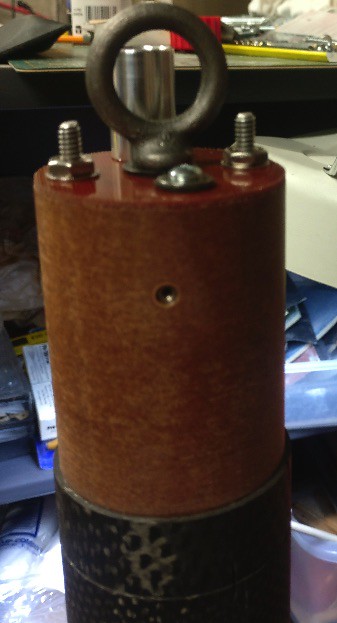
Next I prepped the MMT with the previously epoxied top CR/integrated attachment y-harness, and retainer for gluing. Sorry for the blurry pics but I often have challenges with the cell phone camera auto focus.
I then prepped the adhesives. I used JB-Weld for the root and Aeropoxy ES6209 structural adhesive for the aft end of the tailcone where it meets the internal part of the retainer.
As you can see below, the following steps of gluing it up and any revealing internal pics were skipped. This is because it got a bit busy laying down a bead of ES6209 around the inner circumference of the aft end of the tailcone, and the JB-Weld beads on the MMT. However the result was very clean and worked out exceptionally well.
When I slid the assembly through the tailcone, as expected, I picked up some ES6209 on the outside of the retainer, however I had some paper towel ready to wipe it off. Once this was roughly in place I slid the CR down in order to center the assembly. Then I inserted each fin through the fin slot until the root was flush against the MMT. Once I was certain the fins were squarely in place I slid the MMT assembly forward until the retainer shoulder was against the aft end of the fin tabs. At this stage I slid the CR back up and out of the way to internally inspect to ensure everything was still aligned. The next step was to slightly rotate the MMT assembly back and forth until it built up a small even fillet on each side of the fin. Then I slid the CR back in place, the fin alignment jig on and a rubber band to hold the fins firmly square on the MMT, and left it standing upright overnight to set up.
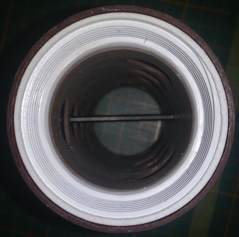
Next up I slid the CR out of the way and visually inspected the fin root fillets by shining a flashlight up through the MMT and looking through the opening in the top of the assembly. This revealed excellent results. Because of the viscosity differences in the adhesives, the JB-Weld pretty much stayed in place, while the ES6209 settled nicely around the external surface of the retainer and tailcone.
As mentioned in a previous post I was planning on laying down some small internal fillets where the fins meet the inside wall of the tailcone, however I opted to foam it instead.
Foaming is something I have only done 4 times. The first time being with Home Depot crack filler foam, which I later discovered after reading another TRF thread was not likely a good idea. The other two times, plus this one I used PML two part foam. From my limited experience I know that prep and pouring it in small batches is the key to good results. That being said I masked all surfaces on the fins, tailcone and MMT that I did not want this stuff to be on. Then I did a dry run with bathroom Dixie cups to ensure they a good fit for the process. I ended up mixing and pouring this in two small batches. I also took some paper towel while the foam was still wet and wiped up some of the overflow, which made for an easier clean-up.
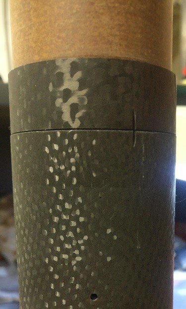
After removing the tape and cleaning-up the top edge of the phenolic coupler, the below was what I was left with. For the most part the clean-up was easy, the majority of effort was put into digging out the excess hardening foam from the top of the phenolic coupler, so that the stepped CR would fit back on.
Last part was to set it aside for a bit to ensure that the foam was fully set-up before I glued the CR in place, only to be forced up. To be safe I left it for an hour then laid down a nice bead of ES6209 on the MMT where I had previously scuffed it up, and the inside and top of the integrated phenolic coupler, and set it aside overnight.
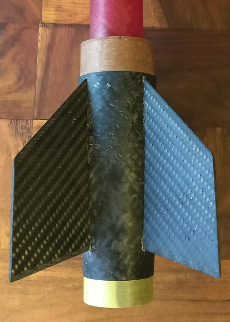
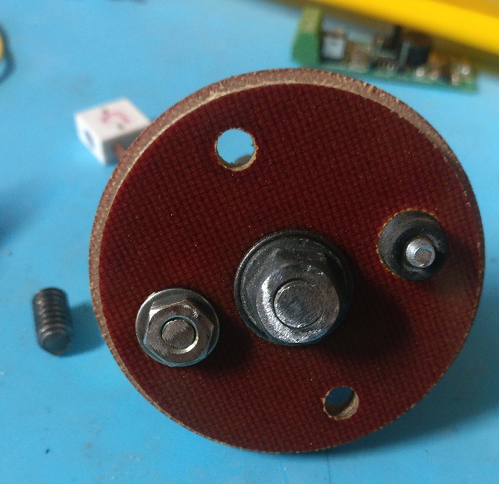
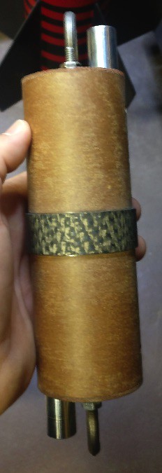
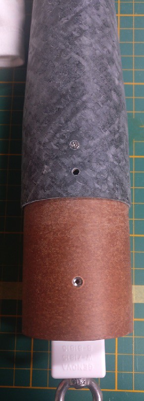
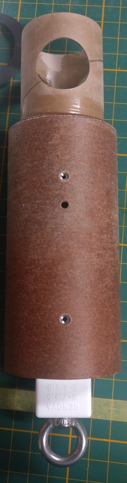
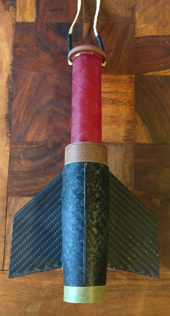
And here is one very sturdy fincan, I would say indestructible but I may find a way. One thing I mentioned that I was going to do, and ended up doing, was laying a small drop of ES6209 on each side of the recovery harness locking pins, just to lock them in place.
At this stage I am wondering how to cram a Loki 38-1200 case in this bird and still have room for my 25' 3 loop 3/16 One Bad Hawk recovery harness and a small drogue, likely 10" or even 8".
Before the discussion turns to drogue vs. drogueless, consider the following. I am only into HPR 5ish years now, and I came into the hobby with an open mind and an assumption that everyone else had something to offer me in the way of advice. However the one caveat was not to take any advice without at least playing the devils advocate. This comes from a realization that people often repeat things that they take on face value from individuals or groups that they respect. That being said it wasn't long until the age old drogue vs. drogueless debate came up in another thread, so I read all sides with an open mind and asked questions. I then took both sides of the argument to task and looked for any videos to support claims, spoke to people in both camps at every launch, and paid attention to each recovery as it unfolded in real-time. That being said, at the end of the day I am firmly in the drogue camp and so it is important for me to use a drogue. Having said that I am still open and I am very aware that this rule will have exceptions, but I don't see the case for that here.
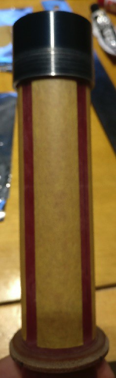
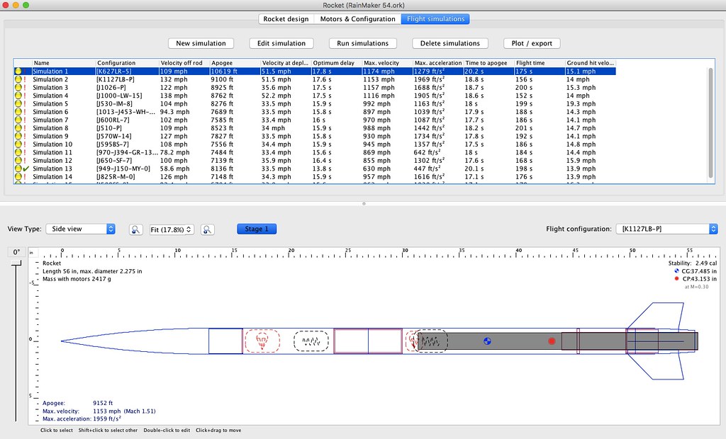
So with that out of the way, as you can see based on the pic below, with the 38-1200 hardware and the K1127LB loaded, space is tight...why should Dave have all the fun. The config below is without the AV-Bay band, which I believe is roughly an inch. It is also adjusted for the retainer and tailcone setup I went with, which necessitated removing about an inch and a half ish of the tailcone. For my main I am leaning towards a 30" FruityChute Iris Ultra Light, which has a really good packing density so I am pretty sure that I can shave an inch or three off the payload tube.
At the end of the day my goal is to play with the tube lengths to gain a bit more length in the booster by taking it away from other areas, but while maintaining the original overall length of the rocket. So I would like to hear your opinions on replacing the booster tube that came with the kit, doing away with the AV-Bay ring, and shortening the payload tube by whatever length I need to make up for the TBD space for this motor hardware, and ordering a new tube from MAC. The old tube will no doubt find it's way onto another build so it's not a waste in my mind but a commitment for another build.")
Unfortunately I don't have the motor hardware in my possession, but hope to have it in a week or so. Once I get it I will mock everything up and see how much space I need to get the recovery hardware in there. I am guessing that I need roughly three inches.
Miraculously I found enough time to get what I wanted done for once.
Gluing up the fincan.
Step one was to mark the MMT where the fins would align, as I have an opportunity to lay down the epoxy bead for the root directly on the MMT, vs. on the fin and through the fin slot which is typically how I do this. I also took some 80 grit sand paper and scuffed up the retainer where it would sit under the tailcone. The plan is to glue the fins and the external part of the retainer where it meets the inside of the tailcone. This is also unique to this build.
Next I prepped the MMT with the previously epoxied top CR/integrated attachment y-harness, and retainer for gluing. Sorry for the blurry pics but I often have challenges with the cell phone camera auto focus.
I then prepped the adhesives. I used JB-Weld for the root and Aeropoxy ES6209 structural adhesive for the aft end of the tailcone where it meets the internal part of the retainer.
As you can see below, the following steps of gluing it up and any revealing internal pics were skipped. This is because it got a bit busy laying down a bead of ES6209 around the inner circumference of the aft end of the tailcone, and the JB-Weld beads on the MMT. However the result was very clean and worked out exceptionally well.
When I slid the assembly through the tailcone, as expected, I picked up some ES6209 on the outside of the retainer, however I had some paper towel ready to wipe it off. Once this was roughly in place I slid the CR down in order to center the assembly. Then I inserted each fin through the fin slot until the root was flush against the MMT. Once I was certain the fins were squarely in place I slid the MMT assembly forward until the retainer shoulder was against the aft end of the fin tabs. At this stage I slid the CR back up and out of the way to internally inspect to ensure everything was still aligned. The next step was to slightly rotate the MMT assembly back and forth until it built up a small even fillet on each side of the fin. Then I slid the CR back in place, the fin alignment jig on and a rubber band to hold the fins firmly square on the MMT, and left it standing upright overnight to set up.
Next up I slid the CR out of the way and visually inspected the fin root fillets by shining a flashlight up through the MMT and looking through the opening in the top of the assembly. This revealed excellent results. Because of the viscosity differences in the adhesives, the JB-Weld pretty much stayed in place, while the ES6209 settled nicely around the external surface of the retainer and tailcone.
As mentioned in a previous post I was planning on laying down some small internal fillets where the fins meet the inside wall of the tailcone, however I opted to foam it instead.
Foaming is something I have only done 4 times. The first time being with Home Depot crack filler foam, which I later discovered after reading another TRF thread was not likely a good idea. The other two times, plus this one I used PML two part foam. From my limited experience I know that prep and pouring it in small batches is the key to good results. That being said I masked all surfaces on the fins, tailcone and MMT that I did not want this stuff to be on. Then I did a dry run with bathroom Dixie cups to ensure they a good fit for the process. I ended up mixing and pouring this in two small batches. I also took some paper towel while the foam was still wet and wiped up some of the overflow, which made for an easier clean-up.
After removing the tape and cleaning-up the top edge of the phenolic coupler, the below was what I was left with. For the most part the clean-up was easy, the majority of effort was put into digging out the excess hardening foam from the top of the phenolic coupler, so that the stepped CR would fit back on.
Last part was to set it aside for a bit to ensure that the foam was fully set-up before I glued the CR in place, only to be forced up. To be safe I left it for an hour then laid down a nice bead of ES6209 on the MMT where I had previously scuffed it up, and the inside and top of the integrated phenolic coupler, and set it aside overnight.
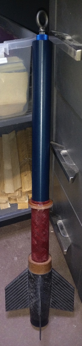
And here is one very sturdy fincan, I would say indestructible but I may find a way. One thing I mentioned that I was going to do, and ended up doing, was laying a small drop of ES6209 on each side of the recovery harness locking pins, just to lock them in place.
At this stage I am wondering how to cram a Loki 38-1200 case in this bird and still have room for my 25' 3 loop 3/16 One Bad Hawk recovery harness and a small drogue, likely 10" or even 8".
Before the discussion turns to drogue vs. drogueless, consider the following. I am only into HPR 5ish years now, and I came into the hobby with an open mind and an assumption that everyone else had something to offer me in the way of advice. However the one caveat was not to take any advice without at least playing the devils advocate. This comes from a realization that people often repeat things that they take on face value from individuals or groups that they respect. That being said it wasn't long until the age old drogue vs. drogueless debate came up in another thread, so I read all sides with an open mind and asked questions. I then took both sides of the argument to task and looked for any videos to support claims, spoke to people in both camps at every launch, and paid attention to each recovery as it unfolded in real-time. That being said, at the end of the day I am firmly in the drogue camp and so it is important for me to use a drogue. Having said that I am still open and I am very aware that this rule will have exceptions, but I don't see the case for that here.
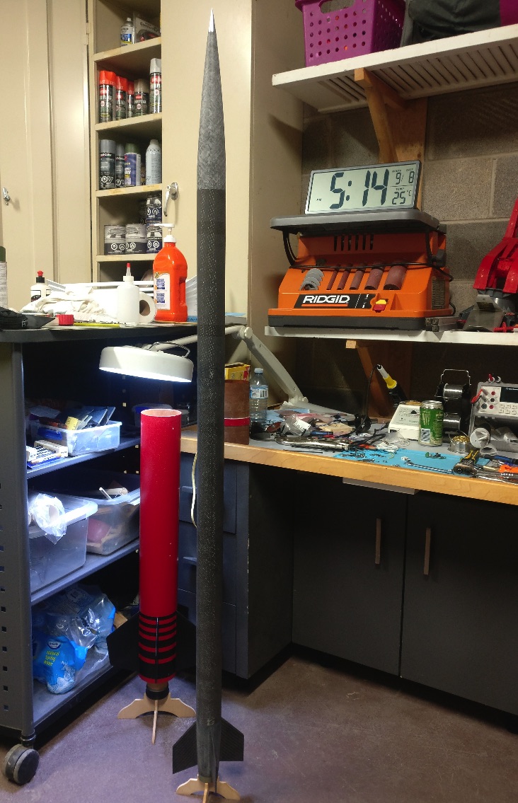
So with that out of the way, as you can see based on the pic below, with the 38-1200 hardware and the K1127LB loaded, space is tight...why should Dave have all the fun. The config below is without the AV-Bay band, which I believe is roughly an inch. It is also adjusted for the retainer and tailcone setup I went with, which necessitated removing about an inch and a half ish of the tailcone. For my main I am leaning towards a 30" FruityChute Iris Ultra Light, which has a really good packing density so I am pretty sure that I can shave an inch or three off the payload tube.
At the end of the day my goal is to play with the tube lengths to gain a bit more length in the booster by taking it away from other areas, but while maintaining the original overall length of the rocket. So I would like to hear your opinions on replacing the booster tube that came with the kit, doing away with the AV-Bay ring, and shortening the payload tube by whatever length I need to make up for the TBD space for this motor hardware, and ordering a new tube from MAC. The old tube will no doubt find it's way onto another build so it's not a waste in my mind but a commitment for another build.
Unfortunately I don't have the motor hardware in my possession, but hope to have it in a week or so. Once I get it I will mock everything up and see how much space I need to get the recovery hardware in there. I am guessing that I need roughly three inches.
Last edited: