[L3] Composite N5800 Flying Case, ~67kft MSL, M3.5

The Rocketry Forum

Help Support The Rocketry Forum:

This site may earn a commission from merchant affiliate links, including eBay, Amazon, and others.
I just got back to Butte after driving from Billings. Astro Anon, I'm sorry this has blown into anything more than a discussion about your project, which I think is very interesting. I didn't intend my position with Tripoli to affect that. Mark's comment about me being a nice guy is infinitely more important to me.
You never actually said you intend to bring this rocket down at 100 fps; you simply said your well built rockets have survived that rate. That's quite a testament to your build techniques.
My concern is range safety and potential for injuries. A rocket falling at 100 fps has nine times as much kinetic energy as one falling at 33 fps. However, I've made that point. I don't think further belaboring that point will help.
Our HPR Safety Code specifically allows " increased descent rates" at Black Rock, but (as you point out) does not specify a range considered safe. I don't wish to add rules. I would prefer to leave it as a discussion point between you and your TAPs. If you ever want to talk to me about it please PM me and I'll send you my phone number.
Steve
 
Sorry they canceled the Hamster Dance, Fred. You would've had a great time.
I can't help but notice your demeanor on the forum is pulled straight from real life. I'm not sure why you have the need to demean those who've just accomplished something great or even those who strive to. This is without a doubt one of the most balls-y L3 flights there've been and seeing it up close was nothing short of incredible so I wouldn't blame you if you were a little jealous. Just don't demean the successful and innovative with nitpicking and pettiness. Try something else like yelling at your neighbors or reddit.

Also, congrats again on the successful flight. The hype around the N5800's died down a little but looking back at the last several attempts it's obvious this wasn't a small feat. The FIRST all composite N5800 and the N record is pretty notable.

Keep it in the casing.

-Casper
 
That is why I thanked him for trying to help. Sorry if disagreement comes off as being rude. I try to not disrespect anyone until they cross the line first, and disrespect was not my intention.

It is cool. I do not mean to sound over the top either- sometimes things come off differently in terms of tone when written versus verbally.

My concerns are what they are, and I do not need to pound on them further. I wish you good luck.


Sent from my iPhone using Rocketry Forum
 
obviously you used Open Rocket for your design work, but the more detailed interior design must have been done with something else. Would you mind sharing a bit of that information?

Tim Ryerse TRA 5796
 
Payload/Coupler

I needed a way to attach the cone to the top of the motor. This also meant that I only had a couple of options for the payload and recovery bay. Originally, I looked at putting the electronics up towards the tip of the cone and making a bulkhead to separate them from the recovery bay below it. I ended up scratching this idea for a couple of reasons, I didn't like the limited space of the bay (taper), didn't like that the electronics where so close to the forward end of the cone, and didn't like security of the bulkhead that would also act as the fore harness attachment point.

Back to the drawing board. I ended up deciding that the most efficient thing that I could do was to use the coupler as the payload bay. This allowed me more room, kept the electronics farther down from the tip & shock waves, allowed me to have a 'better,' space for the chute and a stronger attachment point. Settled.

Initially I chose to make the coupler out of S-glass. At that time, I still wasn't quite ready to let all the optimization go and I wanted the weight savings of a composite coupler. It wasn't until I started looking at the stability at Max. V. that I ultimately decided I needed a little more fore weight. I wanted to stay within 1-1.25 calibers of stability at Max. V (closer to the 1ish caliber side). I played the 'balancing act,' with fore weight and fin design. The Aluminum coupler would add more forward mass, would be relatively easy to make, and allowed me to keep my current fin design. So I sadly gave up on the idea of the composite coupler in favor of Aluminum. Once that was decided, I turned to Mike Passaretti's coupler design for inspiration. Turns out he did a pretty solid job with that and I ultimately made modifications to his design.

The problem with having a full Al. coupler was that I was concerned about radio transparency. Undoubtedly for this flight, I would be dependent on the GPS and RF units for recovery and having the tucked inside Aluminum would likely not be a good outcome. So I essentially came up with a coupler/payload bay design that was a hybrid. Most of the coupler structure was made from Aluminum, whereas most of the payload bay was made from fiberglass. This gave me more forward mass and allowed my electronics to yell away; as ground testing proved.

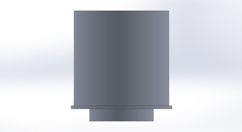
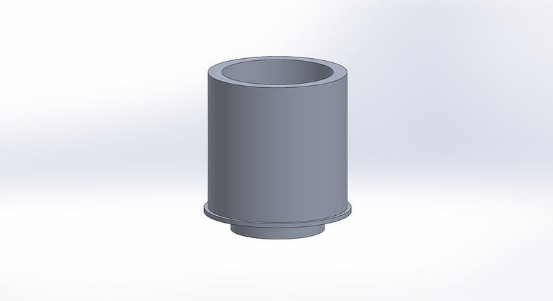
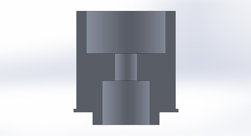
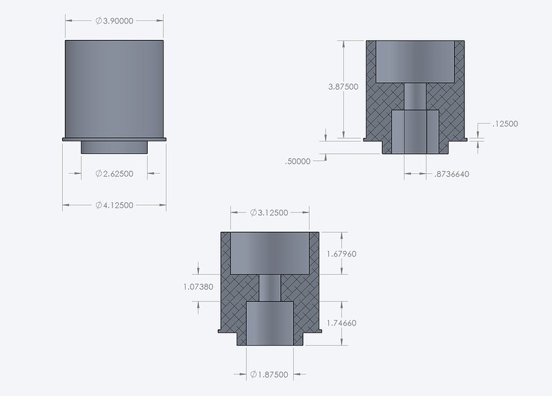
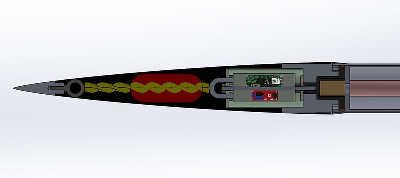
So with the thinking out of the way, it was time to sketch up the final designs and get machining. You can see the design below and how it attaches to the SRM. I will save the electronics and recovery for another post.


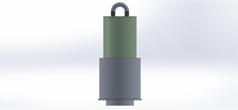
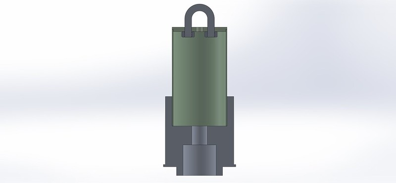
Final design of the coupler. Payload bay is not shown here.


Angled view.


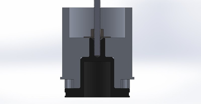
Cross sectional view.


Dimensions.


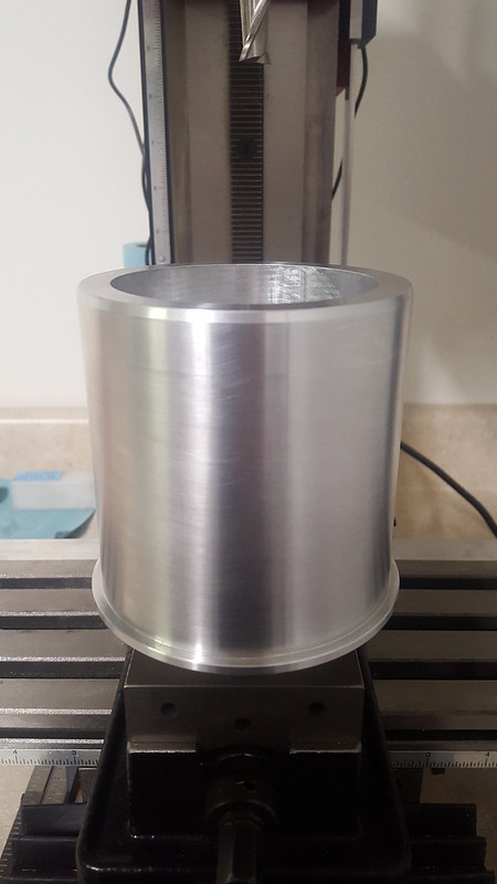
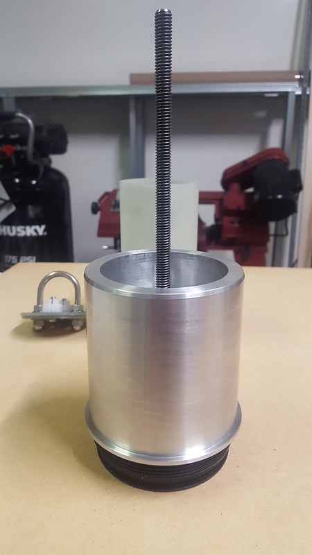
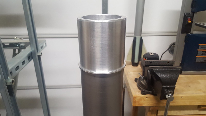
After some metal turning the coupler is done.


Final product.


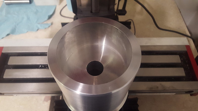
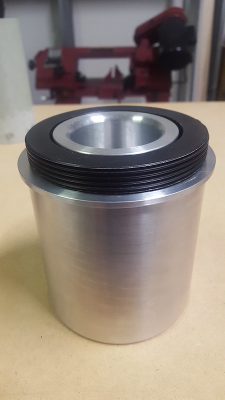
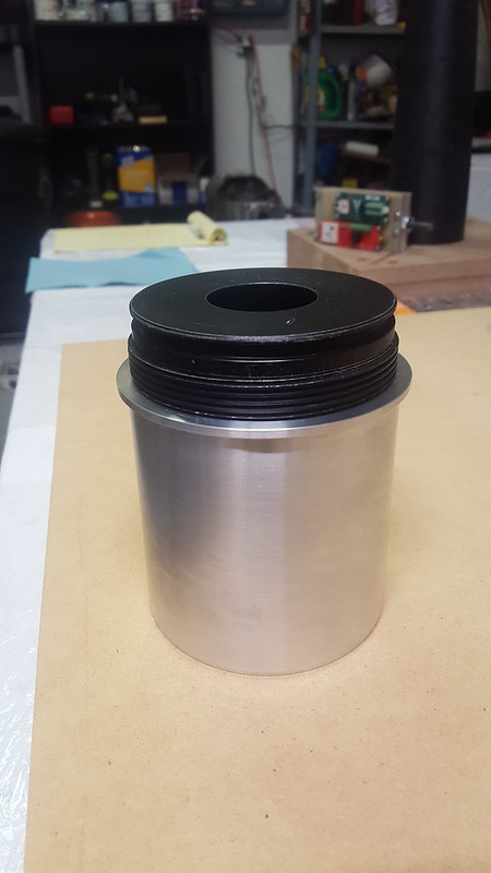
Fore view.


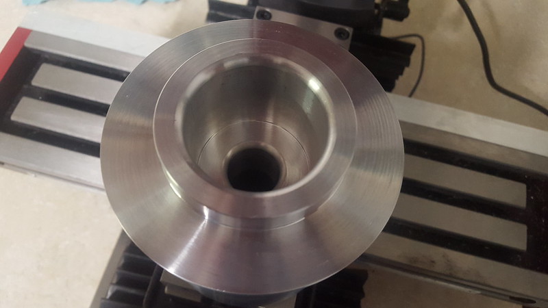
Aft view.
 
obviously you used Open Rocket for your design work, but the more detailed interior design must have been done with something else. Would you mind sharing a bit of that information?

Tim Ryerse TRA 5796

Thanks for the question. You are right that I use OR for the sims. I also cross reference that with RasAero and another program. Never use rocksim.... although it's great for predicting this flight will hit 35kft; if you're into that kind of thing.

As far as the CAD (computer Aided Design) goes, I also use various software. I do primarily use solidworks for CAD, FEA, and CFD. Sometimes I use autodesk stuff and sketchup. Mostly SW though.
 
I just got back to Butte after driving from Billings. Astro Anon, I'm sorry this has blown into anything more than a discussion about your project, which I think is very interesting. I didn't intend my position with Tripoli to affect that. Mark's comment about me being a nice guy is infinitely more important to me.
You never actually said you intend to bring this rocket down at 100 fps; you simply said your well built rockets have survived that rate. That's quite a testament to your build techniques.
My concern is range safety and potential for injuries. A rocket falling at 100 fps has nine times as much kinetic energy as one falling at 33 fps. However, I've made that point. I don't think further belaboring that point will help.
Our HPR Safety Code specifically allows " increased descent rates" at Black Rock, but (as you point out) does not specify a range considered safe. I don't wish to add rules. I would prefer to leave it as a discussion point between you and your TAPs. If you ever want to talk to me about it please PM me and I'll send you my phone number.
Steve

Thank you very much and likewise! I understand your concerns and I do agree that safety (especially in rocketry), is of utmost importance! I don't disagree at all the KE is higher; it's simple physics lol. Just my point is it's statistically unlikely that it would hit someone. I admire your preferences and thank you for the offer! I might take you up on that. At any point it's nice to see that people can communicate rationally rather than blowing things up as most forum convos go. Thank you!

It is cool. I do not mean to sound over the top either- sometimes things come off differently in terms of tone when written versus verbally.

My concerns are what they are, and I do not need to pound on them further. I wish you good luck.


Sent from my iPhone using Rocketry Forum

Thank you! I understand 100%; Very hard to tell context via text.
 
Matt will you have room for camera's?

Sent from my iPhone using Tapatalk

I decided not to include my gopros since I didn't want to increase the length of the payload tube. I had to make a choice and I preferred to have a shorter tube, so there went that. However that doesn't mean I didn't plan on having a camera on-board however. I decided that I could still secure a 'keychain,' camera to the harness. Better than nothing.
 
Last edited:
Creating The Payload Part Of The Coupler

Once the coupler 'turned,' out (see what I did there lol), I started the work on the payload bay. This was relatively straight forward. All I needed to make was a payload tube, sled, and bulkhead. I had G10 plate laying around so I chose that for the material of choice for the sled and bulkhead.


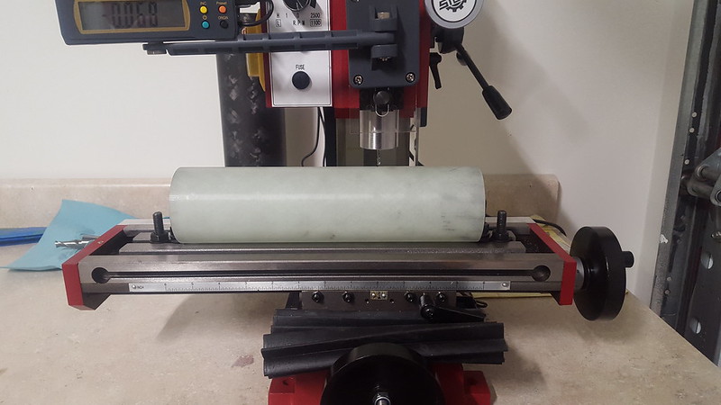
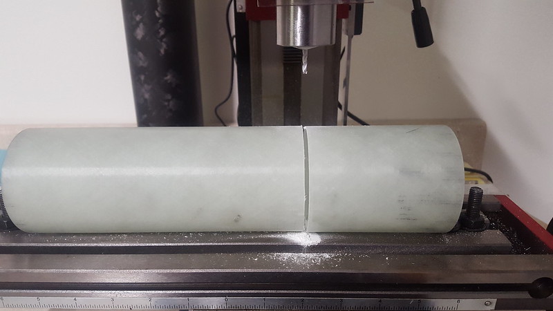
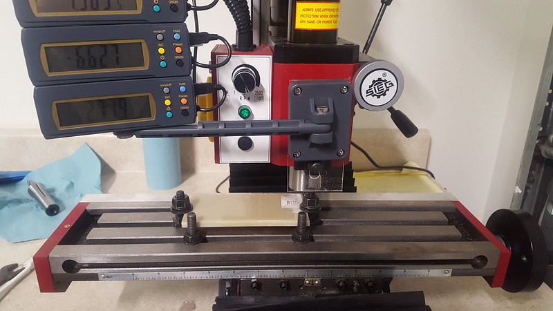
I used a scrap piece of 3" FWFG tube for the payload bay. Once I determined the length I would need to fit everything inside, it was time to get to cutting. I had just changed the blade in my bandsaw and didn't feel like adjusting it to cut 'straight.' Instead I decided to just use my mill and I bolted it down and spun it around, till it was cut. Came out very true.


This is more or less how I secured it to the table. I dropped the end mill down and spun the tube around.


Post cut.


Next came time to attach the payload tube to the coupler. Initially, I decided that I would bound the payload tube to the inside of the coupler, but after further thought I decided to friction fit it in place. That coupled (see what I did there lol), with the all thread; there was no way it was coming out during the flight.

Once that was all together I needed to make my bulkhead and sleds. Another benefit to using CAD programs is that I can print out a template and use that to ease the work.


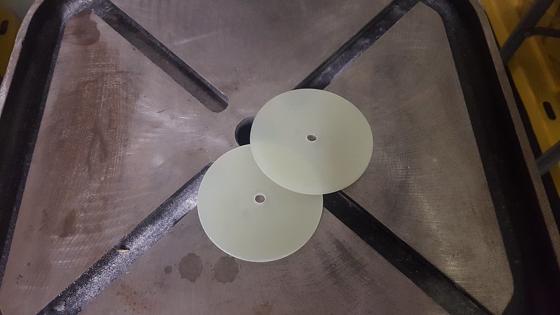
Bulkhead plates made and ready to be bonded together. I probably used JB Weld epoxy for that. In any case, I did use a liberal supply of clamps while the two pieces bonded.


Once the two bulk plates were bonded together, I applied the template I drew up in SW and got to work.


All the pieces in place and the bulkhead is done.


Everything all fitted together. I also drilled two holes into the payload tube.


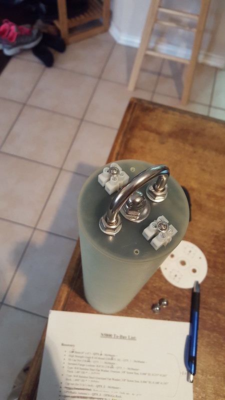
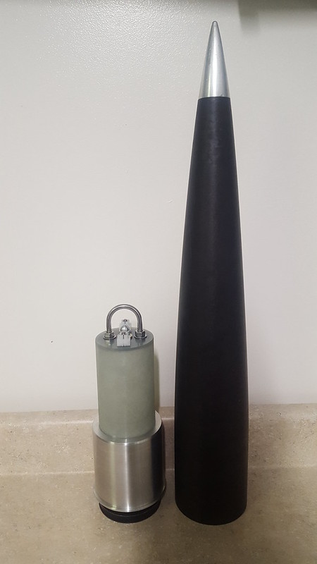
Here is a good photo to gauge the size of all the components and the room left for the recovery gear. I drilled one vent hole into the NC, roughly about 2/3's the way down from the tip.
 
Wow! That coupler is a serious chunk of aluminum.

Lol, sure is! It came out to just less than 3.4 lbs; also cuts about 2kft off of apogee. However it brings my stability at Max. V. from 0.4 to 1.0. All in all it was the trade off I needed and brought balance to the vehicle.
 
Payload/Coupler Assembly.... Assembled


I guess it makes sense for me to show and describe how it all goes together, huh? Here we go.

Describing how it all comes together. There are three hardware components (relative to the fore end) to the CTI 98mm 6G XL motor case. You have the motor case, forward closure, and the retaining ring. So imagine the motor fully assembled with the three components all in place.

Now take the payload/coupler piece and set it into the recession formed by the gap between the forward closure and the retaining ring. This payload/coupler will seat flush with the top of the motor casing and will be slightly larger OD than the motor case. Reason for this is because the my NC is slightly larger OD than the case, as I designed it for a slightly larger OD rocket in the past. Coping with reused components. This also means there is a step that has to be dealt with, but more on that later.

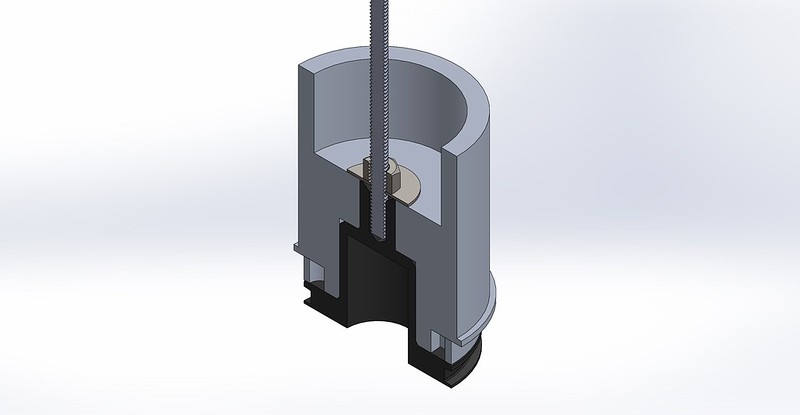
The forward closure resembles a stepped building, with two steps, if you look at it from a cross-sectional view. To deal with this and add support for the connection, there is area that the closure fills within the coupler. Essentially, it is a beautiful seat formed between both parts, matching each part's geometry. Due to this design, there is no possibility of horizontal play between the coupled parts and the only form of movement can be in the vertical axis.

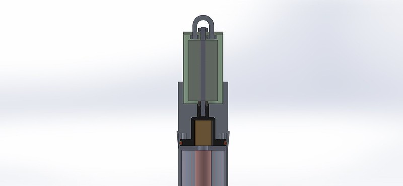
To prevent vertical play, and keep the thing on, a simple all-thread, washer (if you can call it that), and lock nut bolt into the top threaded portion of the forward closure. The all-thread also serves as the means of restraint for the avionics sled, payload tube, and payload bay bulkhead.

There you go, a very easy method in which to connect the coupler/payload without use of epoxy, meaning it is removable.


Cross-sectional view of the forward closure, retaining ring, and coupler. Note how the coupler seats perfectly inside the gap formed between the retaining ring and the forward closure.


Angled cross sectional view.


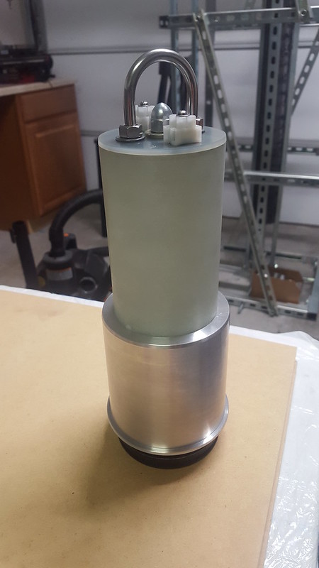
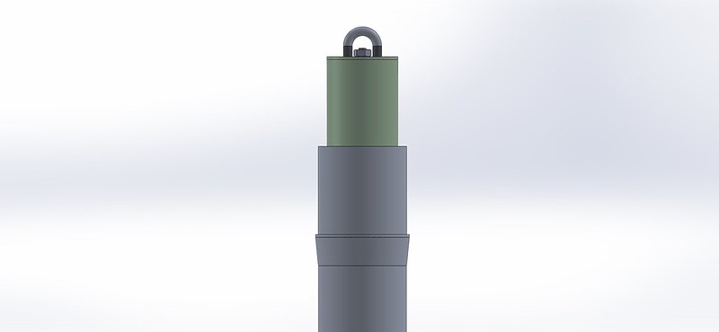
External view of the full assembly stacked up and bolted up.


Cross sectional view of the full assembly all together on top a the fully assembled motor.


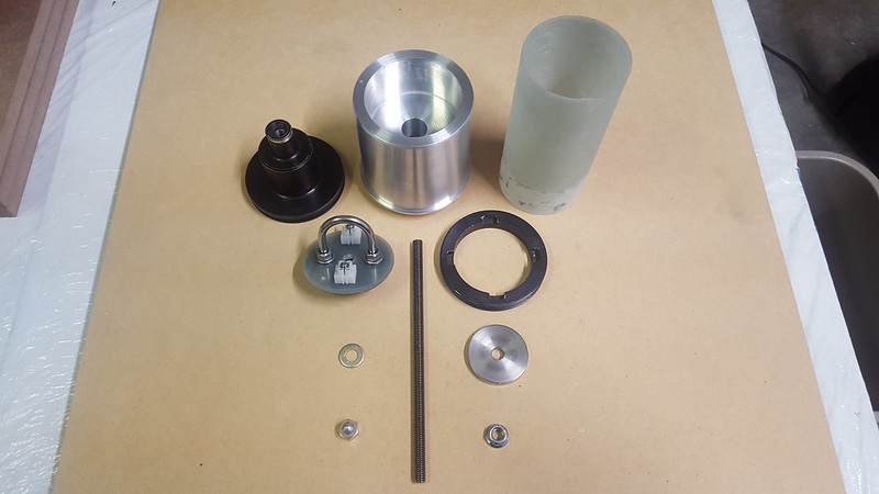
Let's get into some real pictures here. So below you can see all the individual components that make up the whole assembly.


Forward closure, coupler, payload tube, bulkhead, all-thread, retaining ring, bulkhead washer, coupler washer, cap nut, and lock nut.


Retaining ring sits so.


Bottom view of the coupler, showing how the retaining ring and closure fit.


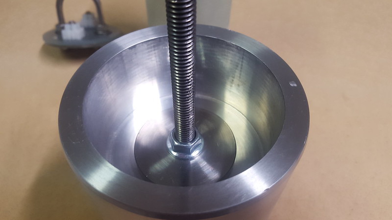
All-thread, washer (if you will), and lock nut secure it all together.


All threaded.


Fully assembled stack.
 
I dig it! Looks well planned and executed.

How tight does your nose cone fit to the coupler? Have you done any thermal analysis or a hot fit check? I'm not sure how much heat you'll get off that forward closure but that aluminum could swell just enough to make a good deployment go bad.
 
I dig it! Looks well planned and executed.

How tight does your nose cone fit to the coupler? Have you done any thermal analysis or a hot fit check? I'm not sure how much heat you'll get off that forward closure but that aluminum could swell just enough to make a good deployment go bad.

I don't think the motor's burn time, combined with 6061's thermal expansion coefficient, and heat transfer coefficient, that the expansion of the coupler would be an issue. If it expands at all, it would be practically immeasurable. This might be a different story if the top of the motor case is acting as the coupler instead.

David

I use the motor case as couplers a lot. The motor case do expand enough to be an issue. I've used a motor tube coupler extension like we're talking about years ago. Mine too was a big chunk of aluminum. I figured it was not going to be affected as much, if any. But, I made the fit a tad loose like I do when using the motor case for a coupler and did not have an issue.

Tony
 
Last edited:
I use the motor case as couplers a lot. The motor case do expand enough to be an issue. I've used a motor tube coupler extension like we're talking about years ago. Mine too was a big chunk of aluminum. I figured it was not going to be affected as much, if any. But, I made the fit a tad loose like I do when using the motor case for a coupler and did not have an issue.

Tony

That sounds like a good precaution to take. However, in this case, the looser fit would raise some concern with me, since I've heard of N5800 attempts shredding due to loose fitting nosecones or couplers. (not sure which attempt exactly, but it might have been cjl's)

David
 
I don't think the motor's burn time, combined with 6061's thermal expansion coefficient, and heat transfer coefficient, that the expansion of the coupler would be an issue. If it expands at all, it would be practically immeasurable. This might be a different story if the top of the motor case is acting as the coupler instead.

David

You may be right that there's not enough heat or time to transfer from motor into the coupler, plus the coupler has enough mass that it can absorb quite a bit. At my day job we usually just assume steady state temperatures and size structures for the induced loads when there's a mismatch in CTE. Haven't had to deal with time dependent variables or moving interfaces like that.

That being said, one quick test is worth 1000 opinions. You could put the coupler in the oven at about 250 and put the nose cone in the freezer, then bring them together for a fit check. If they still fit, great. You're done. If they bind, then consider using an insulator between the motor closure and the coupler, like a phenolic sleeve. Don't change the fit to be looser, change the heat transfer to the coupler.

That's a good down and dirty thought for a test. I like it. Me thinks that chunk of Al will be able to "sink" (absorb) a fair amount of heat before expansion becomes an issue but that sounds like a nice way to be sure.

Yeah, a keychain camera on the harness might give a unique view on descent. I'd probably wrap it in a chute protector and stagger the positioning on the
harness so the protector gets pulled off the camera so it doesn't get coated with burned powder. Kurt
 
Aluminum expands 0.000012inches per inch per degree F. Your 4" slug will gain .006" if it's heated from 75F to 200F. I really doubt that it's going to heat up that much in 30 seconds. The FG nose cone should be much more stable.
 
I dig it! Looks well planned and executed.

How tight does your nose cone fit to the coupler? Have you done any thermal analysis or a hot fit check? I'm not sure how much heat you'll get off that forward closure but that aluminum could swell just enough to make a good deployment go bad.

That's a very good question! Thank you for bringing this up. The fit is pretty tight; a little dust can cause it to bind. I do not remember the exact fit, I would have to go through my notes and look at the dims. Sorry, made the parts a long time ago; that is also why I do not have too many interesting pictures available.

I am not all that concerned with expansion causing separation issues. I haven't done any 'hot,' fit testing and honestly I do not know what temperature the forward closure will get. If I had to guess, it would be less than 200F. Critical exposure time will be just under a minute (time to apogee). There is also loads of grease (added) and a forward insulator disk (phenolic) in the SRM, that will help fight the transfer. The coupler is also a good chunk of metal and should be able to absorb quite a bit. i don't think it will get hot enough in the allotted amount of time to expand to the point where the cone would not separate.

Considering the thermal expansion and heat transfer of the coupler, coupled (see what I did there lol) with the max exposure time of ~55 secs and the mass of the coupler; it'll more than likely be fine.


That's a good down and dirty thought for a test. I like it. Me thinks that chunk of Al will be able to "sink" (absorb) a fair amount of heat before expansion becomes an issue but that sounds like a nice way to be sure.

Yeah, a keychain camera on the harness might give a unique view on descent. I'd probably wrap it in a chute protector and stagger the positioning on the
harness so the protector gets pulled off the camera so it doesn't get coated with burned powder. Kurt

That is what I have done in the past, well chute protector or.... hotel wash clothe etc lol. Thanks for the reminder, it is very helpful. Stuff like that can easily be forgotten. What did you mean by stagger it? Thank you.
 
Last edited:
That sounds like a good precaution to take. However, in this case, the looser fit would raise some concern with me, since I've heard of N5800 attempts shredding due to loose fitting nosecones or couplers. (not sure which attempt exactly, but it might have been cjl's)

David

I would speculate that CJL's N5800 flight more than likely shredded due to instability. He had three very small fins relative to the diameter of the rocket. A rocket I might add that was going to go + Mach 3, would of pushed the caliber unstable at higher speeds. But you are certainly right that some of the N5800 attempts have failed because of the coupled sections.
 
(Snip for brevity's sake)

That is what I have done in the past, well chute protector or.... hotel wash clothe etc lol. Thanks for the reminder, it is very helpful. Stuff like that can easily be forgotten. What did you mean by stagger it? Thank you.

If possible, attach the camera protector at a point just above the camera on the harness with a little slack so when the harness goes taut, the protector will be above and out of the camera field. Or.............. If you like wash cloths, just wrap the
camera and kiss the wash cloth goodbye when it's ejected. I'd probably try to fold it so it will flop off the camera and head to terra firma on its own. I've never tried that myself but since you mentioned it. Might work.:wink:
Kurt
 
It's Electric


With the payload out of the way, it's time to talk about what goes in it. For this flight I wanted to cover my bases with the flight computers and GPS units. I have been burned before with GPS units and really wanted to make sure I recover this rocket; especially since it is for a record attempt and my L3! I chose to use three total GPS boards, with two acting as flight computers and two acting as tracking. If I had to, I could also use them for directional tracking with RF. I will go over all of the programming settings in a latter post.


Let's get into the gritty details a bit, shall we?

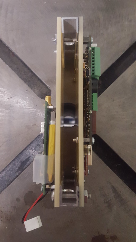
Please reference the above posted CAD image. It's an extremely simple design. Basically you take two G10 plates, bolt them together with 2 pieces of Aluminum channel. Drill two 3.8" holes in the channel so that it can slide onto the 3/8" all-thread. The all-thread is what holds it in place, within the payload bay. The three different boards are on standoffs on the outside of the G10 plates and all the cables and batteries are on the inside, sandwiched between the two G10 plates. Oh, and no switches.... don't need them, just using the good ole twist and tuck method.

I opted to use the following electronics for this project:

  1. AltusMetrum TeleMega - Serves as the primary flight computer. Serves as the secondary GPS unit. Transmit's to a proprietary ground station. Using one single cell 900mAh 3.7V LiPo battery for unit power, tracking, and pyro channels.
  2. AIM XTRA 2.0 - Serves as the secondary flight computer. In addition to the other units; as an contingency this can be used as a directional RF tracker. Using one single cell 850mAh 3.7V LiPo battery for unit power, tracking (if needed), and pyro channels.
  3. BRB 70cm 100Mw - Serves as the primary GPS unit. Transmits to a Kenwood TH-D72A. Using one supplied single cell 800mAh 3.7V LiPo battery for normal power and tracking.


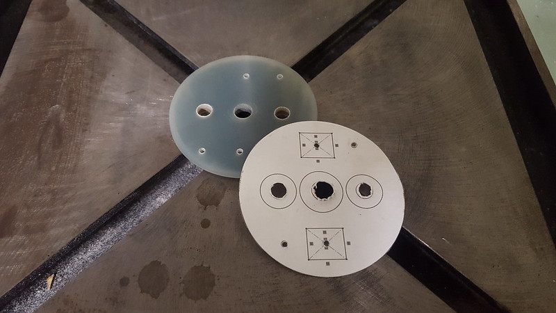
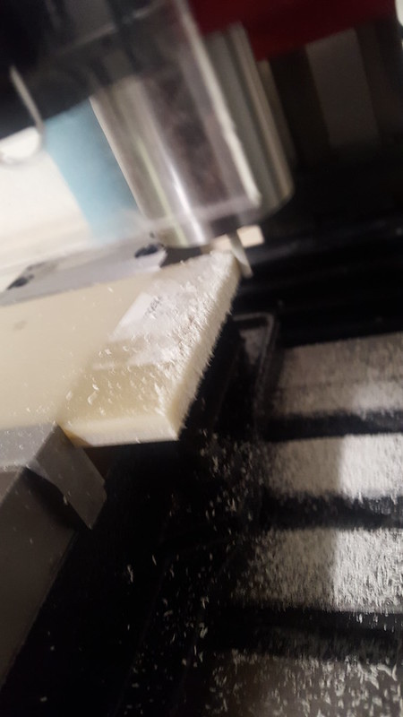
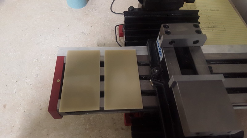
For the sled I used a sheet of 1/8th inch thick G10. I first cut the two plates into approximate rectangles and then through them on the mill to get to the exact size I calculated. This would allow me enough room for the electric things and ensure a flawless fit into the tight payload bay.


I make the fiberglass dust.


With the two sled plates out of the way, it was time to start drilling.


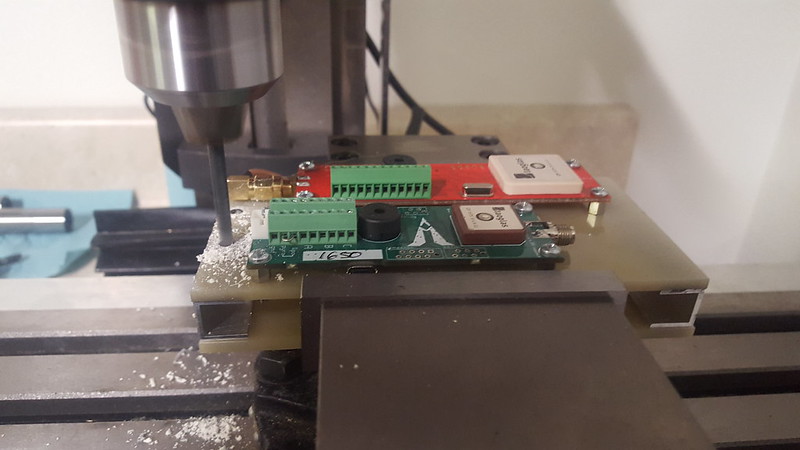
So I used CAD software to print up templates of where everything was to go and then started drilling. I apparently did not take any pictures of this step; just visualize the bulkhead template shown earlier. I started off by drilling the stand off holes for the electronics on the mill. I then bolting the stand offs and their respective hardware into place. I did not glue them into place. I then took some Aluminum channel and cut it to spec and then bonded it onto one of the sleds. This allowed me to essentially create a sandwich sled. All of the boards and antennas on the outside and the batteries, and cables are sandwiched in between the two sleds. Following this I drilled holes through the G10 sleds and into the Aluminum channel, allowing me to install the hardware to bolt this whole mess into an electric G10 assembly!


You can see all of the boards on the sleds with the Aluminum channels and hardware installed. You can also see two 3/8" holes drilled into the Aluminum channel on the side of the channel that runs perpendicular to itself. This allows me to slide the electronic sled onto the all-thread and keep it secure. In the future projects that are a bit more optimized, I imagine eliminating the all-thread to save weight and increase simplicity. The payload tube itself would act as retention for the electronics sled, thus requiring no other hardware. Obviously, that cannot work on this projects design, as the coupler assembly is held in place by that all thread and lock nut.


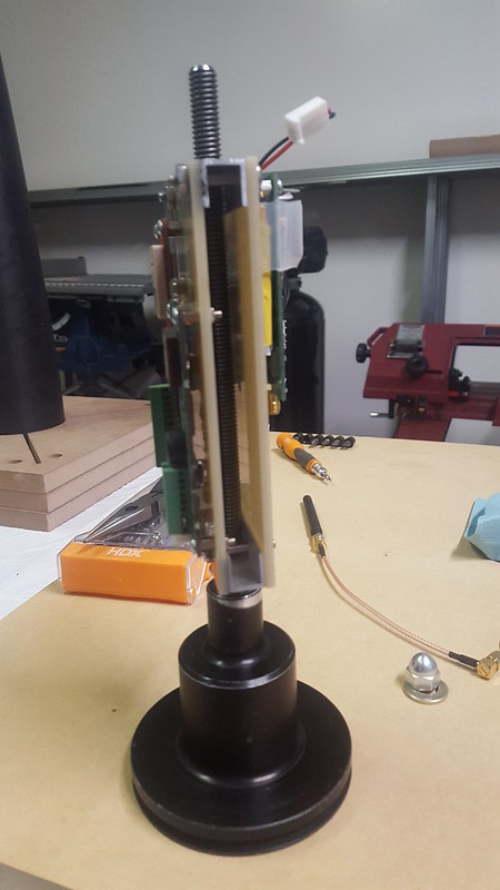
The payload shown without the coupler/payload bay present. You can see how the the electronics sled slides down the 3/8" thick all thread that screws directly into the forward closure of the motor. In this picture the batteries and antennas are not installed. You can however, see one of the antenna's on the table. I used the standard antennas that came with the unit, but used a SMA coaxial RF extension cable to be able to mount it to the board. This allowed me to have a shorter overall payload bay and gain recovery space (which was already tight).

As far a s the batteries go, I used one 3.7V single cell ~900 mAh LiPo battery per unit. The batteries went in between the two electronic sleds. There is no hardware to hold the batteries in place, instead, per design, the batteries are pushed into place and let be. Under 'normal,' conditions I would be worried however with the internals of the sled and the payload bay there is no room for the batteries to have any play in any axis. The all thread and payload tube walls prevent any play from side to side, the G10 sleds prevent any play in and out, and the installed hardware inside the sleds prevent any play from up and down. All things considered, it is very secure as is.

You might note that the forward closure is black except towards the top by the 3.8" hole area. It was out of round and I had to turn it down just a tad to get it to fit into the coupler.
 
If possible, attach the camera protector at a point just above the camera on the harness with a little slack so when the harness goes taut, the protector will be above and out of the camera field. Or.............. If you like wash cloths, just wrap the
camera and kiss the wash cloth goodbye when it's ejected. I'd probably try to fold it so it will flop off the camera and head to terra firma on its own. I've never tried that myself but since you mentioned it. Might work.:wink:
Kurt

Oh, I gotcha. I am sure it would work. Yeah, that would be the best way since I hate littering.... but unfortunately I have done it before without tying up the 'protector.' Not too proud of that, but it is what it is.
 
Back
Top