Estes Cosmic Interceptor

The Rocketry Forum

Help Support The Rocketry Forum:

This site may earn a commission from merchant affiliate links, including eBay, Amazon, and others.

RCgothic

Active Member
Joined
Jul 3, 2017
Messages
42
Reaction score
0
My first two rockets flew brilliantly this weekend, an Amazon and a Crossfire, and now I'm looking to challenge myself.

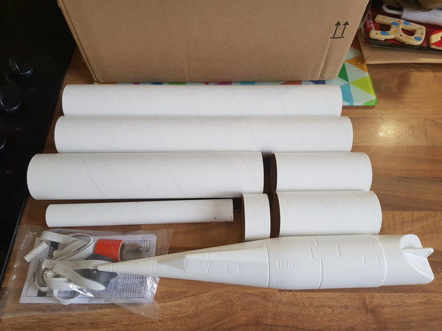
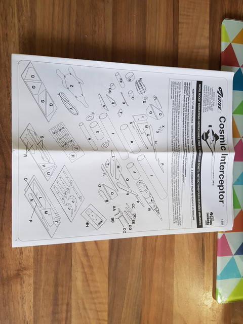
I've liked the look of a Cosmic Interceptor.

product_image


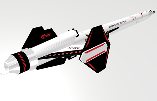
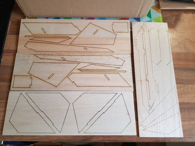
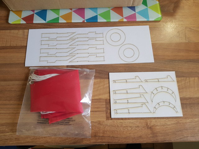
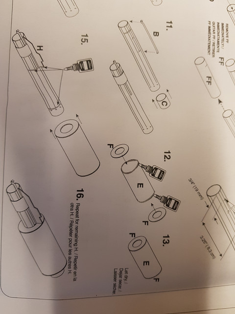
It was either that or a QCC explorer for my next kit, and this is the one my local vendor had at the field today! It can take 24mm D or E motors, with a stuffer ring for the shorter Ds, and I was recommended a pair of D12-3s for it. I'm told it can also fit Cesaroni Pro24s. So this is my next build.

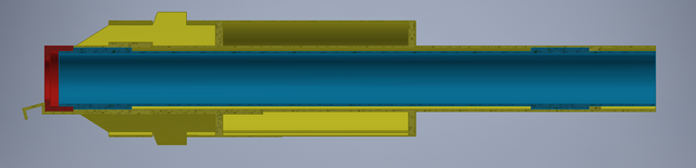
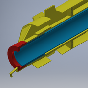
Before I start, I have an option: it looks like a relatively easy mod to 29mm motors, with an adaptor back to 24mm. Trim the strakes, larger motor tube. The original 24mm motor tube can be fitted with some balsa strake extensions an extra motor clip, and retained by the original clip on the new 29mm tube. It should retain its lines at the rear quite nicely. Is this mad? I've got no way to check the stability with that extra mass moved backwards.

Does anyone know if there's an Open Rocket file of the Cosmic Interceptor somewhere?
 
Good luck with the 29mm mod.

I built one of these a couple of years ago. Flew it on Aerotech 24/40 motors. I was sad to see Estes discontinue the model. I broke down a couple of weeks ago and bought two more kits while I could still find them. I plan to combine the kits. Leave off the scoop and use 4 sets of wings on one extended body. I'll leave it 24mm and use AT reloads in it.

I was not able to find a rocksim file on this kit. I hope some one has one......:)
 
OR can't handle this type of fin configuration AFAIK.

I built mine stock and it flies really well on an AT F35 motor (24/60 reload). I've never really felt the need for a larger motor.
 
So that's one vote for and one against the option so far. My main reasons for considering this are:

1) To challenge myself with what looks like an easy mod.
2) To give myself a greater range of motor selection.

What altitude did you get on the F35 mikec? About 900-1000ft? Is it your flight recorded on Rocket Reviews?

My field has a 3000ft limit before dual deployment is required, so there isn't any point pushing that boundary. That said, if it's going to about 1000ft on an F then seems unlikely to me that it'll break 2000ft on a G.

I've had the tape measure out and the as supplied motor tube would have a max motor length of about 8.25". I think that rules out P24-6G and P29-4G or higher as I don't want to extend beyond the existing motor mount limits.
Helpfully, Cesaroni don't give specifications for their 4 or 5 grain P24 motors, so I think that rules them out as well.

So what does that leave me with? P24-3G gets up to Fmax and P29G gets Gmax and babyH.

The P29 seems to be closer to the limits of my field, is a better construction challenge and might even be an L1 candidate eventually. However without an OR sim I'd be nervous about stability, though it's fins are very large they're ahead of the motor mount. Are there any more old-school methods I can use to investigate?

The P24-3G is by far an easier mod and presents fewer stability questions so might just be an obvious opportunity not to overcomplicate.
 
I now follow Tim (Wildman's) Second Law on all builds (even 13mm motors): "No Engine Blocks!".

Building for the CTI 24-3G is lovely, but that 6G will keeping calling to you. Addressing stability is easy enough - if even needed. Longer motor - more weight forward.

Thrust rings are your friend. Even ones made from masking tape strips.

And I don't think CTI makes 4 or 5 grain 24mm. Just 1-3 & 6.
 
I'm literally going by Cesaroni's website, which has hardware codes for 24mm 4 and 5 grains but no reload specs or dimensions. Weird.

Anyway, here's what came in the kit:


If I'm sticking large motors in this I'm definitely papering the balsa. I hear full page A4 sticky labels are good for this.

I've also been warned from a previous build thread that those page 3 marking guides are printed directly over crucial instructions on p4, so I'll be taking a photocopy of it tomorrow. I'll be taking mikec's advice for a longer shock cord too.

I am convinced by Charles_McG to go for P24-6G capacity. There's plenty of space in that body tube for shock cord and parachute.

I'm still up in the air over P29 capability. If I do it will still probably only be 3G. It would be a shame to have such a lovely model shred, particularly that air intake has no business being taken transonic.
 
I have not seen any Pro24 4/5 grain hardware or reloads available for sale anytime in the last 1.5 years.

Like Charles mentioned above, leave out the engine block. The Pro24 has a thrust ring lip at the back, and a 24mm motor retainer is all you need for retention (unless you want to learn friction fit taping. That setup just requires a tape thrust ring on blackpowder motors.

It sounds like a good project. Make it fun!
 
Might want to brace the joint where the tie-fighter things attach to the wings. Its a weak spot should they be the first to hit the ground on landing.

Should you decide to stick with the 24mm mount, you'll still have Es and Fs available with the Aerotech 24/40 or 24/60 casing. I've had great flights on the E18 reload as well as the SU E30-4T
 
I've had the tape measure out and the as supplied motor tube would have a max motor length of about 8.25". I think that rules out P24-6G and P29-4G or higher as I don't want to extend beyond the existing motor mount limits.
Doesn't matter if you're not using an engine block, the motor can just stick past the forward end of the MMT.

Of course at some point you'll tear the wings off without additional reinforcement. I can't really say where that would be. I could imagine that a Pro29 H54 would be OK, and an H410 probably not.
 
Fins
For the tie-fighter fins I was planning a pretty thick epoxy fillet, perhaps 5mm. I suppose I could put some triangular dowel in the corners? Or would a large fillet be enough? Speaking of, the last epoxy I tried was horrible and dried rubbery so it wouldn't sand. Any UK brand recommendations?

Motors
For motors (besides estes D12s) I'm going with Cesaroni because my local vendor is RocketsAndThings and the Pro24 and Pro 29s are what they stock.

Ok. Time to inject some reality into this. I want to challenge myself, not destroy a gorgeous rocket. Thanks mikec again for motor comments. I did a bit of maths:

The most thrust Vmax Pro29-3G H410 could pull over 115Gs. That's totally ridiculous and would definitely shred.
The least thrust Mellow Pro29-3G G33 would be around 14Gs. That's maybe a better ballpark, although at 4.4s burn time would I ever see it again?
White Longburn and Red Lightning at H54 and G54 are around 24Gs at take off.
One further consideration - Pro29s can take up to 2 spacers. That means the ideal purchases are 6XL, 4G and 1G to get all the sizes. Luckily the 4G is about the same length as the 24mm 6G, so might not be an issue.

For Pro24-6G, every single one pulls more than 25Gs. If it can withstand 40Gs we're good. Otherwise probably best to stick with the Pro24-3Gs.

Are there any rules of thumb for max thrust?

Shock Cord
The estes elastic is a bit short and I'm taking the recommendation to replace/augment it. Cosmic Interceptor is about 1m tall. I'm thinking 2m of 1/4" kevlar with some shrink wrap padding joined to the original elastic ribbon with a square knot and a couple backup knots. Is the estes teabag mount going to be sufficient? Or do I need to consider putting in a bulkhead I can use a proper anchor on? This could be going much faster than a regular Interceptor at deployment.
 
I've got a few of these kits, 2 built, 3 unbuilt and was looking at doing a 29mm for the next one. I've found that the 24mm reloads do a great job of lofting it up there. (F39-6 is a nice fast 1000 foot flight). I just want the 29mm BP F15 for the smoky slow takeoff. (Aerotech F12 reload may do the same thing, I just haven't tried that one yet) Anyhow, I've had no issues with the stock build handling the F39 reload or the F44-4 Single use. It WILL go up on a D12-3, but it's a LOW flight and I'd recommend a 5 foot+ rod or a rail. E12 is a nice flight on these. I don't have a "full flight" video but here's the E12. 4 second delay was perfect. [video=youtube;36d5sijbufw]https://www.youtube.com/watch?v=36d5sijbufw[/video]
F44-4 is a little short on delay, F39-6 is great.
 
Thanks for that swakat. The 24mm or 29mm optionality is going to add mass, so a D12 may end up being underpowered. It's something to bear in mind.

I'm struggling a bit with finding some of the parts I'm going to need, and I think it's a terminology thing.

What do you call the suffer tube Estes use to fit engine mounts inside a motor tube? Is it a motor mount coupling tube?

What do you call the thicker tubes that go over the outside of the motor mount to retain the motor hook? Are they just centring rings?
 
Mostly they are called tubes and rings of one sort or another.

Motor tubes are usually, but not always, body tube of a certain size. BT50 is 24mm motor tube. PSII kits have 29mm motor mount tubing, and places like eRockets sell it, too.

The green rings are centering rings, usually named for the two body tube sizes they go between. Like CR2050 to go from BT20 18mm motor mount to BT50 24mm motor mount.

The clip retention ring or band is a different material. I've used a centering ring with a notch cut in it to fake it.
 
I've done a bit of modelling!


This is the 29mm configuration. It's basically identical to the stock 24mm except with larger parts. I'll need to take 2.5mm off the strakes with sandpaper, and I lose about 3.5mm length. It doesn't spoil the lines at all!

Parts required:
29mm motor mount tube 10" long.
29mm to 24mm centering ring 1" long (to stop me being tempted to stick a 6XL in in the distant future and as a 24mm adaptor thrust ring.)
29mm motor clip retainer, 1" long.
2" to 29mm centering rings x2.


These two pics show how I adapt to 24mm. Parts required for the motor mount:
24mm motor mount 10" long.
29mm to 24mm centering rings 1" long x2.
There's no engine block because the Pro24 has a closure lip and the BP D12 is probably a bit underpowered. If I need to fit one I can use tape as suggested.

Parts required for the retainer adaptor:
29mm motor mount tube 0.5" long
29mm to 24mm centering ring 0.5" long.
29mm to 18mm centering ring ~3mm thick.

Now to see if I can track these down! Thanks Charles_McG. Centering rings for the PSII tubesmight be tricky.
 
You could always build for 29mm, then just add a 29mm to 24mm adapter to run the smaller motors.
 
True, but I like the idea of building my own. I think what I'm going to do for the centering rings is wrap my own from gummed paper tape over a mandrel. That way I have control over the exact sizes, particularly the motor hook retainer which is being awkward at 29mm+.

That just leaves motor tubes which are easy enough to get, and the 2" to 29mm spacers which I think are going to have to be modified and reinforced originals.

Any ideas for shock cord mount? I've bought some 2000lb Kevlar with some shrink wrap to use as padding.
 
I cut a notch in the forward motor mount centering ring, thread the Kevlar through, tie it around the motor tube, slip it up to the aft side of the forward centering ring and bury it in glue. I make it long enough to run backwards through the motor tube, put a loop in the end and tie on the real length of shock cord - Kevlar or elastic - and then shove all back through the motor mount and out the front.
 
I like that idea too. It will require a bit of creative assembly reordering, as the motor mount rings have a coupling tube between them which won't slide over them, so there's no way I can tie anything behind the fore motor mount ring if I follow the standard order of instructions.

20170920_172109.jpg


If I put the fore ring F on first and assemble from the aft end it should work out. Alternatively I can add a third ring purely as a shock cord mount.

Anyway! First progress! Some bits are still in the mail, so I'm starting with the bits I can do - the body tubes, intake grill and nose cones. Joining the two body tubes with PVA is simplicity itself. I cut the template out with scissors, marked with a pencil, and then cut the intake cowling out with scissors. I'm not sure If recommend that method, the scissors I used at least had trouble rounding the curves of the tube and it was difficult to prevent them cutting inside the lines, but the end result wasn't bad.

20170920_172619.jpg

20170920_172941.jpg

20170920_173229.jpg
20170920_180218.jpg
 
Tacked together the intake grill with super glue on a sheet of wax paper just to hold it in shape.

This is probably going to be the most vulnerable part of the model exposed to near-mach airflow. So I'm going to substantially bulk up the non-visible frame sections with epoxy.

 
I like that idea too. It will require a bit of creative assembly reordering, as the motor mount rings have a coupling tube between them which won't slide over them, so there's no way I can tie anything behind the fore motor mount ring if I follow the standard order of instructions.

20170920_172109.jpg


If I put the fore ring F on first and assemble from the aft end it should work out. Alternatively I can add a third ring purely as a shock cord mount.

Anyway! First progress! Some bits are still in the mail, so I'm starting with the bits I can do - the body tubes, intake grill and nose cones. Joining the two body tubes with PVA is simplicity itself. I cut the template out with scissors, marked with a pencil, and then cut the intake cowling out with scissors. I'm not sure If recommend that method, the scissors I used at least had trouble rounding the curves of the tube and it was difficult to prevent them cutting inside the lines, but the end result wasn't bad.

20170920_172619.jpg

20170920_172941.jpg

20170920_173229.jpg
20170920_180218.jpg

You can add Kevlar to the coupler sandwich.

Notch the fwd CR like you would normally for this mod.


Once the CR-Coupler-CR sandwich is built, tie you Kevlar around the smaller tube then slide it off - drop the loop into the Sandwich tube from the fwd end and feed the BT in through the aft end into the loop you tied earlier, and ensure the line is in the notch when you feed the tube through the FWD end of the coupler.

This is what I did for my BT60 two stage at the fwd end, as the MMT tube went all the way into the payload tube:

https://www.rocketryforum.com/showthread.php?141195-My-first-2-stage
 
Also a decent suggestion, though I wouldn't be able to pot the Kevlar in glue that way.

Actually I've decided that cutting down some oversize OD centering rings for 29mm motor tube will be easier than opening up my 2" to 24mm centering rings to 29mm.

A nice side effect is that I can cut the new centering rings down to the coupling tube ID so it can slide over the installed centering rings and I'll have access to the motor mount tube and Kevlar loop before then. Best of all worlds!
 
With all the epoxy and rear end additions, you may end up needing extra nose weight to keep the flight straight. Chances of going transonic are going down.
 
It's not a minimum diameter kit and it's certainly not designed for that regime, so no big deal if the nose does require a little weight. I've actually stated thinking about putting the parachute up there! It's half a mind towards dual deployment at a later date.

Estes say the model weighs about 280g. I wouldn't be surprised if it ends up around 350g or more.
 
Added some epoxy to the intake frame. Wasn't the neatest job ever, but nobody's going to see it. Doesn't stick to the wax paper either, which is good to know! I'll need to sand it down slightly to finish, which could be interesting because this brand of epoxy dries rubbery which is annoying. I need to find a different brand that sands before doing any work that will be visible. Any UK suggestions?


Also cut out some bits and sanded the edges flat. The engine strakes need 2.5mm taking off the bottom so I'll wait until the new motor tube arrives before doing that. The rings are probably going to be used in another project once the replacements arrive.


These are the tie fighter fins. They fit together nicely.


A forward wing strake, the fin end plates and a tail fin, plus two vertical strakes.
 
I miss this model. Mine was destroyed by months of weather in a tree. I may have to attempt a clone now that they're OOP.

Good luck with the build!
 
Sorry to hear about your Cosmic Interceptor! It's a gorgeous model. Still in stock from certain suppliers?

A few new tools turned up today: digital calipers, Kevlar rope, heat shrink, and A4 sticky labels.


I've also finished cutting out various bits:


Airfoiling and papering these is going to be complicated. I've got a lot of CA on order for sealing the paper leading edges.

Some observations I've made with using sticky labels to paper fins:

1) it's a hellova lot easier then wood glue and plain printer paper

2) it doesn't stick as well as woodglue/paper

3) make sure you sand the fin surface then REALLY carefully clean and remove the balsa sawdust off the fin before using the label. I've found a little norwex microfobre cloth is PERFECT for this. Failing to do so means you lose much of the stickiness as it just sticks to the little fibres and can lift.

4) large fins - the labels can delaminates from the fin in the middle of large fins (and by large, I mean with spans larger than 60mm. I had a booster that the paper completely lifted off the middle of the fin under the paint work, so the fin was essentially a giant painted paper bubble with a balsa fin inside somewhere.

5) I've tried applying thin CA to the middle of the paper to overcome (4), but with the Avery labels I have, I've discovered the thin CA doesn't penetrate through the paper - there's something in the paper / adhesive layers that prevents it soaking through. It works at the edges, but not really well in the middle of the fin.
 
I really appreciate all of the above info. I'll try and bear it all in mind.

At the moment I'm sanding leading and trailing edges. With a composite wing like this is important to remember which edges are leading/trailing and which are mid wing. For some panels this isn't a uniform answer for a single edge. I've already messed up twice by sanding an edge supposed to be in the middle of a wing and an edge that is normally a leading edge but then meets another strake. Nothing that I can't put right luckily! There's not much to show in the way of photos right now though.
 
Back
Top