Possible to stage Estes motors without tape?

The Rocketry Forum

Help Support The Rocketry Forum:

This site may earn a commission from merchant affiliate links, including eBay, Amazon, and others.

billdz

Well-Known Member
Joined
Feb 10, 2017
Messages
1,377
Reaction score
121
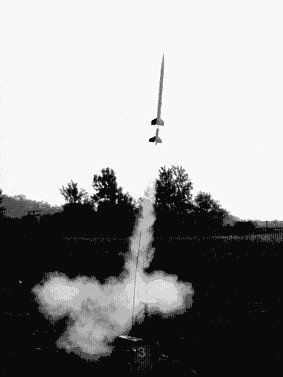
I brought my Klima Delphinus two-stage rocket back from Europe but I'm not sure if it can fly on Estes motors. On all the Estes two-stagers I have seen, the booster and the upper stage motors are connected together with tape. That's not possible with the Delphius, there's over a 1" gap between the motors (the Klima booster lights a fuse on the upper stage booster). I could tape a cardboard sleeve between the motors.

Anyone know if the Estes boosters can ignite the upper motor without a direct taped connection?
 
Sure. Many examples abound from classics like the Estes Shrike to the currently-on-clearance Estes ARFs with the accessory boosters. The key thing is to vent gases so that the stages aren't pushed apart prematurely and this becomes more important as the distance increases. For example the ARF boosters work fine stock - with no venting - with a D12-0 in them but if you use a C11-0, thereby increasing the distance to the sustainer nozzle a half-inch or so, they need to be vented or sustainer ignition becomes iffy.
 
Anyone know if the Estes boosters can ignite the upper motor without a direct taped connection?

Absolutely. There are configurations called "gap staging", where the booster and next stage engines are several (up to 12) inches apart. Someone (Estes? Centauri?) had something called "pop-and-go" staging where each stage use a conventional motor mount with engine hook. [edit - it was the Estes Omega that used this] Tubing extended the"fire" from the lower stage into the nozzle of the next. I made a two-stage Fat Boy with a similar concept. You have to vent the pressure generated when the lower stage engine burns through so that the ignition is transferred without blowing the stages apart prematurely. The attachment below shows that the upper stage engine mount extends a lot further below the stock location. It actually sticks into the motor mount tube of the booster, which is 24mm. The square holes are to vent pressure from between the stages, back through the centering rings, out the bottom of the booster so the stages are not blown apart before upper stage ignition (there are similar holes in the upper centering ring).

LB-2.JPG
 
Absolutely. There are configurations called "gap staging", where the booster and next stage engines are several (up to 12) inches apart. Someone (Estes? Centauri?) had something called "pop-and-go" staging where each stage use a conventional motor mount with engine hook. Tubing extended the"fire" from the lower stage into the nozzle of the next. I made a two-stage Fat Boy with a similar concept. You have to vent the pressure generated when the lower stage enging burns through so that the ignition is trabsfered without blowing the stages apart prematurely.

Ditto Sooner.boomer!
Gap Staging has been around for decades. as stated above you do have to vent the air above the first stage motor to allow the hot gasses and burning bits to ignite the upper stage. Generally 1/8" to 1/4" holes just below the upper stage motor work well for gap staged rockets.
 
Thanks for the replies. So with my 1.25" gap, all I need to do is make vent holes and I'm good to go? No need to tape a sleeve between the 2 motors? This rocket uses conventional motor mounts with engine hooks, see the attached pics.

20170710_123550.jpg

delphius instructions.jpg

Delphius package 2.jpg
 
I had not noticed this previously, but the lower and upper centering rings on the booster actually have pre-cut vent holes, see pic.

vent holes.jpg
 
You better believe it. I never use tape. It's old school for "Pop-n-Go" staging. Some ppl here swear by using tape, some don't. But most of my staging failures came from using tape. nuff said.
 
I had not noticed this previously, but the lower and upper centering rings on the booster actually have pre-cut vent holes, see pic.

and is the engine mount tube itself already vented into that space as well? The hot gases need to get into the sustainer nozzle, the cold gas in between the motors needs a pathway to get out of the way.

some more info on staging from Apogee: https://www.apogeerockets.com/Tech/How_2-Stage_Rockets_Work
 
"and is the engine mount tube itself already vented into that space as well?"

No, only holes in the centering rings of the booster.
 
You better believe it. I never use tape. It's old school for "Pop-n-Go" staging. Some ppl here swear by using tape, some don't. But most of my staging failures came from using tape. nuff said.

Pop-n-Go was the name Estes used for the rockets that were designed to NOT use cellophane tape.
 
So are the vent holes in the booster motor centering rings sufficient or do I need to drill "1/8" to 1/4" holes just below the upper stage motor work"?
 
It was not clear from the one picture that you posted if both the top and bottom centering rings have slots. Or, how far down the sustainer motor inserts into the booster tube relative to where those centering rings are located. You want the vent to let air escape to the bottom of the booster, but not to the top to blow it off the sustainer before that motor lights. More pictures would help give the correct advice if you still have questions. You might need to add an additional centering ring to force the air to vent out the bottom slots, for example. Or the top slots might need to be closed up. Where are the holes going in the engine tube relative to the centering rings?

You also have the option of venting through the both the internal engine mount tube and external body tube of the booster also, if you don't mind changing the look of the rocket.
 
Both rings have identical slots. When assembled, the bottom of the upper stage motor is 1.25" from the top of the upper stage motor and 1.5" from the slotted top upper centering ring on the booster. There are no holes in the airframe or the engine tube.
 
OK, well, the easiest modification would be to drill 1/4" hole all the way through the booster, from one side to the other, just below where the sustainer engine nozzle is located when mated up. This vents from the engine tube directly outside through the airframe tube. You should seal the vents in the top centering ring, this may allow the pressure to pop the booster off before sustainer ignition. The slots in the bottom centering ring are not needed, but won't hurt.

If you don't want to change the external body tube, this option may be a little tricky. How do you punch a hole in the inner engine tube at the correct location that far down the tube, after it has already been assembled? If you can figure out this, please post pictures to show us how. And in this case also, you must plug up the slots in the top centering ring, you want it to vent out the bottom slots and those must be kept open.
 
Thanks for the replies. Today was the club launch, I used the Delphius in stock configuration (vent holes only on the motor mount) and the upper stage motor ignited properly.
 
Yes, I have up to a 1.5" gap in some of my 24mm two stagers. just be sure and vent the gap so the pressure doesn't blow off the top stage prematurely... Austin Powers style.
 
The motors in the Quest Navaho AGM and Zenith II kits are set up where its is impossible to tape the motors together when built stock. I added a pair of pressure relief vents to the booster of my Navaho AGM. No staging failures yet, but I have only used A8-5s in the sustainer. One of these days, I will try a B6-6. The Estes and later Semroc versions of the Omega and the Shrike also did not use taped motors. Also, many of the classic Centuri staged kits didn't require the motors to be taped together.
 
Absolutely. There are configurations called "gap staging", where the booster and next stage engines are several (up to 12) inches apart.

Here is an old picture of my Aerobee in flight. Here is an example of gap staging, but here there is no tube between the motors. The distance between the motors is approximately 3 inches and the burning material from the booster jumps a gap of nothing but air to ignite the upper stage.
MRArobee.jpg
 
I had not noticed this previously, but the lower and upper centering rings on the booster actually have pre-cut vent holes, see pic.

View attachment 324877 View attachment 324876

Both rings have identical slots. When assembled, the bottom of the upper stage motor is 1.25" from the top of the upper stage motor and 1.5" from the slotted top upper centering ring on the booster. There are no holes in the airframe or the engine tube.

Thanks for the replies. Today was the club launch, I used the Delphius in stock configuration (vent holes only on the motor mount) and the upper stage motor ignited properly.


Nice ! Thanks for the follow-up billdz and thanks for flying the Delphius as-is with the vent holes in the booster centering rings. Vented 'out the back' so to speak. :) I'd like to try that some time myself.
 
All this talk about pop and go, and nothing about CHAD (CHeap And Dirty) staging... The Semroc Lil' Augie has a form of staging where the sustainer motor is inserted inside the body tube from the top of it, and held in place by a pin, the booster motor is simply slid up inside the back end.
 
All this talk about pop and go, and nothing about CHAD (CHeap And Dirty) staging... The Semroc Lil' Augie has a form of staging where the sustainer motor is inserted inside the body tube from the top of it, and held in place by a pin, the booster motor is simply slid up inside the back end.

If you're gonna talk CHAD staging, then you should be talking about simply taping a booster motor to the motor of what would normally be a single-staged rocket. The booster motor just hangs off the back and free falls once the upper stage ignites.
 
Back
Top