Help on selecting a first two stage high power rocket kit

The Rocketry Forum

Help Support The Rocketry Forum:

This site may earn a commission from merchant affiliate links, including eBay, Amazon, and others.
Jim,

I think this is what I love about staging, I had to read that a few times to understand the proceedure.

So I assume the easymega is connected to the deployment charges? If so you could add the same switch or shunts to the deploment channels to remove the risk you are concerned about.

You are really testing the easymega at this point, which I agree with, but is there a reason the PF CF and timers need to be on outside of the easymega?

Those are my intital questions but I will take a look again when I get home from work.

Thanks for taking a look. I think it is good to ponder how these wifi switches get incorporated into staging. There are many issues (and I thought I'd seed the discussion with my issues).

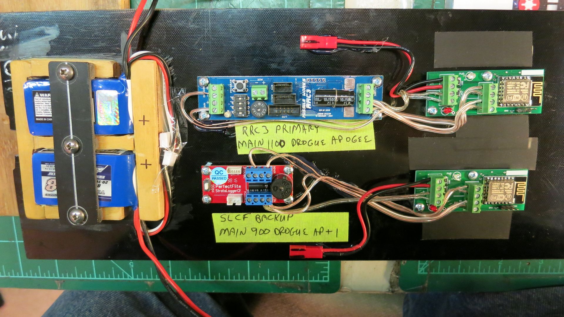
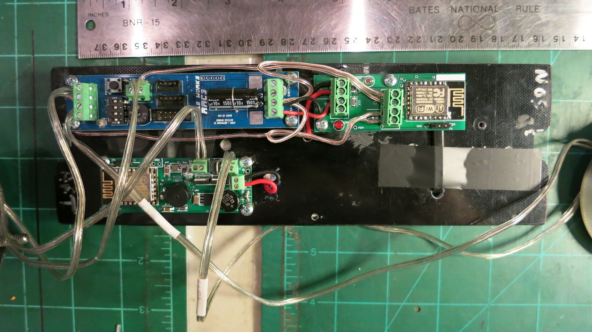
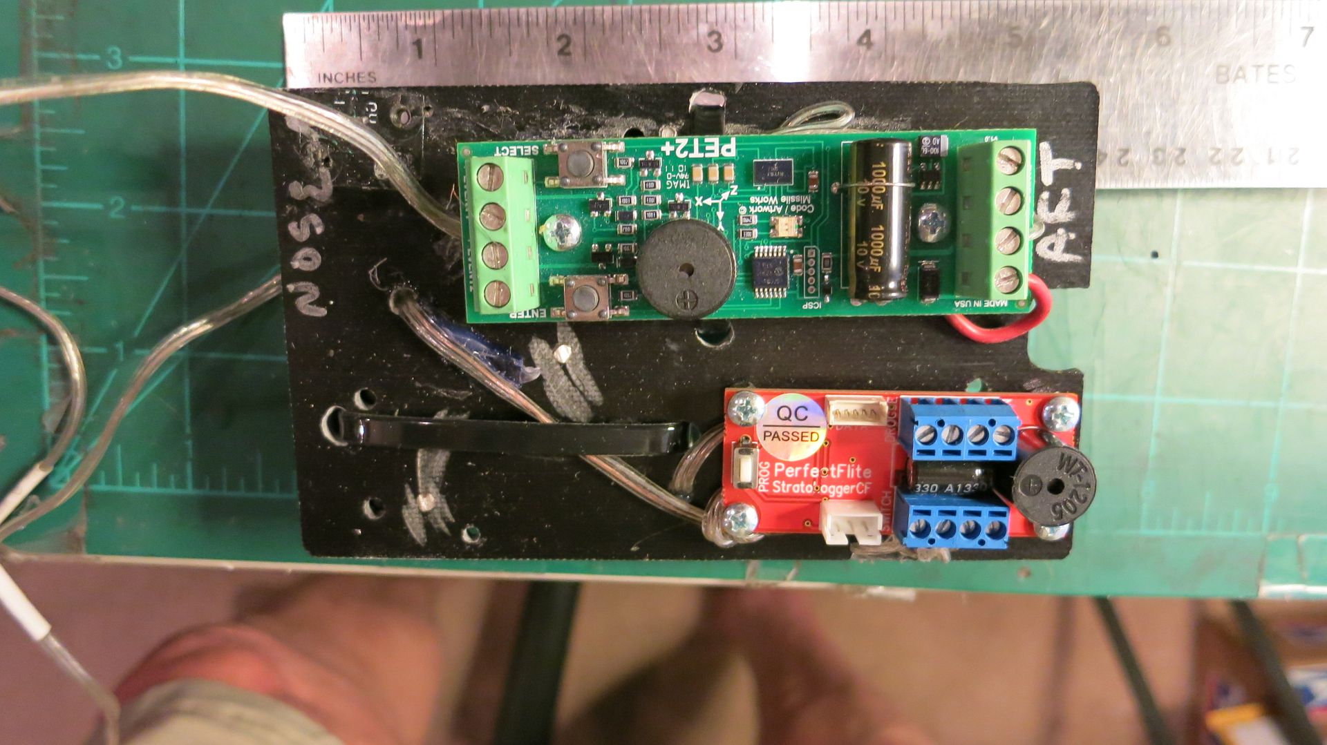
The easymegas control the motor ignition events but also multiple deployment and separation charge events. Only the ignition circuit has the shunt switches. When the wifi switch closes, it just turns on the easymega, just as would happen if you closed a manual power switch for the altimeter. Since you wouldn't normally use switches on deployment charges (altimeters are reasonably good at not firing charges on power-up), there isn't really a need to install them. My concern was about manually lifting a rocket from horizontal to vertical with charges live as part of the all-up test. This would be what happens in the actual arming sequence, but the all-up test could be modified to avoid this particular hazard (just turn on the other electronics after the rocket is vertical, and before closing the wifi switch, instead of when it is horizontal).

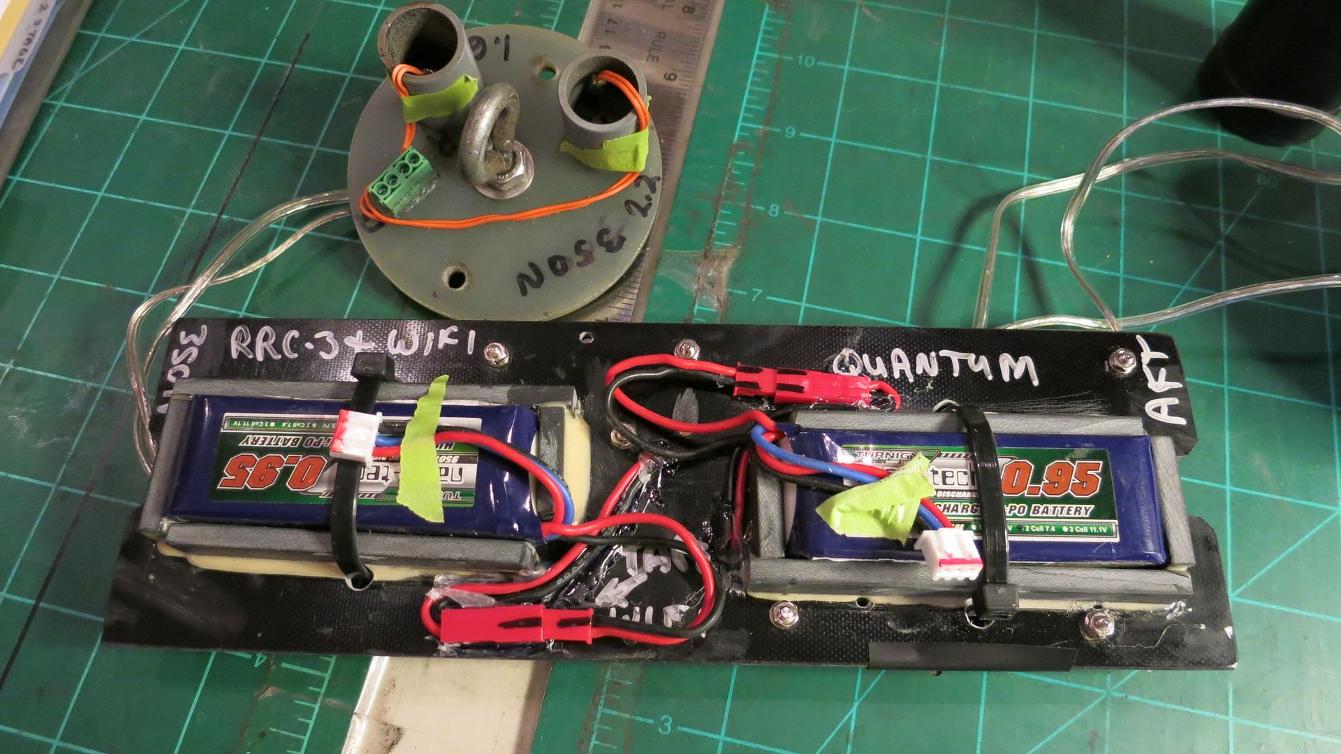
In general, however, there will be the issue of how to arm the other electronics if you are using wifi to arm your motor ignition. One option would be just to climb the ladder for these other electronics. I can avoid that for my flight because there is no real hazard arming these with the rocket horizontal (no people are needed to lift the rocket), but this might not work in most cases. Another option would be to use a single wifi switch to power all of the electronics. I think you lose too much redundancy doing this. Maybe the best option is just to have separate wifi switches for each altimeter/timer (or get wifi-enabled altimeters). In a new build, this is what I would do, although hearing the continuity indications with the rocket horizontal is an advantage for me. The three stager has eight devices that make noise - it's quite a symphony when everything is turned on.

Jim
 
Jim,

- Place shunts in "disconnected" position with rocket horizontal and igniter out of motor
- Turn on other deployment electronics (PF CF in 2nd, timers in 3rd)
- Close the wifi switch. Assuming the easymega does not turn on, place shunts in connected position
- Place rocket vertical in stand (see pic). This is the potentially unsafe step I'm not sure about with deployment electronics active. Maybe I should wait and just do this after the rocket is vertical?
- Turn on wifi switch and check easymega continuity indications
- Move shunts to disconnected, open wifi switch to easymega and turn off wifi switch itself, turn off PF CF or timers.
- Insert igniter, place on rail, and repeat above with 3rd stage.


What I am focusing on is what happens here, so you could reduce your risk by testing the PF CF and other timers while horizontal. Then turn them off and put the rocket in the stand, and then turn the wifi switch on.

- Place shunts in "disconnected" position with rocket horizontal and igniter out of motor
- Turn on other deployment electronics (PF CF in 2nd, timers in 3rd)
- Close the wifi switch. Assuming the easymega does not turn on, place shunts in connected position
- Listen for CF/Timer continuity
- Turn off PF CF or timers.

- Place rocket vertical in stand.
- Turn on wifi switch and check easymega continuity indications
- Move shunts to disconnected, open wifi switch to easymega and turn off wifi switch itself
- Insert igniter, place on rail, and repeat above with 3rd stage.

So while it is on the stand, it will never be moved with the deployment charges active.

However, Once on the rail I see your issue. I think you are implying that the rail raises with some sort of motor where a bunch of people, or even yourself, do not have your hands directly on the rail? If so, I would turn everything on except the easymegas as you described before raising the rocket. I think a lot of complex rocket failures can happen getting lost in the symphony of beeps and not arming everything. I think doing it horizontal as you describe lessens that risk.

The starters are not active until the rocket is vertical with all the back up altimeters armed in your procedure.
 
However, Once on the rail I see your issue. I think you are implying that the rail raises with some sort of motor where a bunch of people, or even yourself, do not have your hands directly on the rail? If so, I would turn everything on except the easymegas as you described before raising the rocket. I think a lot of complex rocket failures can happen getting lost in the symphony of beeps and not arming everything. I think doing it horizontal as you describe lessens that risk.

Yes, I can raise the rocket without any people involved. I have a winch on my vehicle, about 75 feet away, and I can pull the rocket up from horizontal with no one at the rail. I think it makes this approach possible.

Jim
 
Hi Jim & Evilash,

Have you Gentlemen ever tried using a physical device as a shunt? In the Radio Control model aircraft community several manufacturers make wiring devices with a "Remove Before Flight" plug which is mounted on the exterior of the aircraft. Depending on the setup, a plug is either inserted or removed to allow power to reach the electric motor. You can power up the aircraft to test all of the flight controls. Only the motor cannot be activated.

I have had numerous problems with WiFi or Bluetooth devices syncing up. Do the WiFi switches you are talking about work flawlessly?

What do you think about using a female Deans connector with a mounting plate on the exterior of the sustainer? The two altimeter motor circuit firing leads could be attached to the two terminals on the Deans connector. The feeder wire that runs down to the retention device can also be connected to these terminals. When the male shorted out "Remove Before Flight" flagged plug is removed you have a hot firing connection. When the Deans male plug is inserted it effectively twists the ematch wires together shunting the ematch.

You Guys are the experts. I am just asking if you think this would work. If this works, you could raise the rocket after all of the electronics have been tested and turned on as per Jim's instructions. You could use a dowel or pole with a hook to pullout the "Remove Before Flight" Deans shunting pin.

I would say that anything that would be suitable as a switch in a high power rocket could be used. The Deans plugs might also be OK. Just remember that any shunt that you make has to be ground tested so you know that the battery won't overwhelm it. 9 volt and small LiPo's are good in that respect. Also, you could disconnect something with a pole, but you would need to have a way to reinsert it if necessary. In my upcoming flight, I will have a ladder to access the switches if need be. I'm just hoping not to have to use it.

I like the wifi switches. I'm amazed that I was able to put three of them together that worked, given the teensy electronic parts. I'm told they're huge by surface mount standards, but they seemed pretty small to me. Flawless? No, not entirely. I'm using an iPhone and Shield tablet to connect to them. The iPhone sometimes objects to the fact that the wifi connection isn't connected to the internet. There can be other connection issues. Overall, it's about 95% good, and when there is an issue, just disconnecting from the network and then reconnecting seems to take care of it. I'm committed to them, but I still think it's a good idea to have a way to get to them if need be.

Jim
 
Lots of times any connectivity issues while testing WiFi Switches are due to the presence of a lot of WiFi SSIDs in your home. They're virtually flawless out in the field where you don't have 100 neighbors' routers banging on your iPhone. Multiple WiFi switches work quite well together... I've done this numerous times.
 
I added a Wifi switch and a Quantum altimeter to my 2 stage, and have had no problem connecting to them with my iPhone. I did switch over to Safari from Chrome, had some problems with Chrome, but it could have been me not knowing how to use it. I'm using the switch to power up an RRC-3 for my airstart on the sustainer, but may change that when I have more experience with the Quantum. The 22 page airstart manual for the Quantum is a bit daunting.

I liked the switch so much, i built two more and installed them in my Ultimate Darkstar. The Avbay is about 8 ft. up when it's on the pad, and I hate ladders.
 
Wifi switches are nice but only if you have the room. I have never had any problems with mine but they are battery hogs. You want at a minimum a 500mAh Lipo.
 
Room is not a problem in the Ultimate, you could have a hoedown in here:
002.jpg


When I made the battery box, it was sized for 9v batteries, but with a bit of work with the dremel, I resized them for a 800 mAh lipo.
My 2 stage is a 3" rocket, but still no problem fitting everything in. Can't find the pic's right now, but I will post them up later.
I also want to go over my procedure for hooking up the sustainer igniter on the rail, but still have to do a dry run and take pictures of it.
 
Hi Wayco,

I would like to see a picture of your 3" rocket AV Bay board. You have enough room to fit a HAL 2001 computer in your Ultimate Darkstar. The challenge is to see haw you can get everything to fit in a 3" tube.

Wayco you mentioned in a past post that you successfully inject West Systems epoxy for your internal fillets in your Darkstars. Tim from Wildman recommended this technique. I have built my 3" Wildman booster section. With a 3" body tube and a 54 mm motor mount it was no problem to make traditional internal fillets. That is using three motor mount centering rings. The rear ring isn't epoxied in until all of the internal fillets have been completed.

I feel that this has to be stronger. You get to double the number of internal fillets. Now the fins are also filleted to the booster tube. Furthermore I also filled the internal void with expanding foam. This make a rock solid fin can.

The sustainer is another matter. I cannot see anyway to install the internal fillets except by injection. There are three inches of internal space at the bottom of the sustainer body tube for the interstage connection. Not a drop of epoxy can get into this area.

My concern is that the West System epoxy will seep through the rear centering ring jamming up the interstage space.

Any feedback Wayco?

Bob
 
My concern is that the West System epoxy will seep through the rear centering ring jamming up the interstage space.
Bob

When building mine, I stood the fincan on end-upside down, holding slightly tilted.
Dropped several drops of CA, running down motor mount to rear CR. Then roll the slightly tilted airframe 360, the CA will seal the outer CR to airframe joint.

Just be sure to have already sealed the conduit running through CR, so it can't leak. Now injecting is simple. 5ml per fillet should do it.
 
Leave it to CJ to come up with a clever way to seal the rear ring. Since the sustainer that I am flying is one that he built, I'm glad that he answered your question. With all the darkstars I've built, a good tight fit of the centering rings on the motor mount tube is essential. Stacking the rings with the fin sandwiched between them will space them correctly for insertion after the MMT is installed. I have never added foam to an injected fincan, and never had a fin come loose from the lack of the extra material.
I will post up some pictures of my sled on the sustainer and interstage coupler later today.
 
Thanks Jim for the tip on sealing the sustainer's rear centering ring. Wayco I would love to see how you fit all of The avionics into that 54 mm AV Bay.

Thanks,
Bob
 
Wayco how are you switching on your altimeters in the 3" rocket? I can't see you having room to use the WiFi switches.

All the best,
Bob
 
The OP has already purchased a Wildman kit. The discussion is about how to build it.
Your other threads/posts preclude you.:flyingpig:
Read the thread before you jump in with baseless kurfuffle about something of which you know nothing. Or as I refer to it pas:

"a know it all, that don't know it all.....after all!"
dont have to be rude about it, I just forgot to read it all, ok also I don't know it all, but I would like to think I had sufficient enough education to reply to this. Ok I'm just trying to get into the forum, so don't be rude about it, I don't think either of us should waist our time (probably took you 30 seconds to a minute just to think and type that) being rude. I hope you have a great day, Peace
 
Wayco how are you switching on your altimeters in the 3" rocket? I can't see you having room to use the WiFi switches.

All the best,
Bob

Well I think if you have a room problem, you can always make the avbay longer. Plus, the avbay he has pictured is so big he does not have to even use the other side of it. The wifi switch and the batteries could be on the oppisite side as the altimeters. I have not done it in a 3 inch with wifi but I would not forsee an issue with the room that is left over in my 2.6" sled. I think the cool thing about LIPOs is they are all different sizes and shapes that you can buy according to the space you have.
 
Well I think if you have a room problem, you can always make the avbay longer. Plus, the avbay he has pictured is so big he does not have to even use the other side of it. The wifi switch and the batteries could be on the oppisite side as the altimeters. I have not done it in a 3 inch with wifi but I would not forsee an issue with the room that is left over in my 2.6" sled. I think the cool thing about LIPOs is they are all different sizes and shapes that you can buy according to the space you have.

were can And, were would you to buy wifi switches, and are they better opposed to other method switch systems?
 
Hi Jim,

The Wildman 3" two stage kit interstage comes as follows:

1) A 3" coupler tube is used to join the sustainer and booster sections together.

2) A section of 54 mm motor tube fits over a 54 mm bulk plate which is epoxied onto a bulk plate that fits inside of the 3" coupler.

3) Plywood centering rings secure the 54" tube into the 3" coupler tube.

4) There is a screw on cap that seals off the new 54 mm AV Bay.

Sincerely,
Bob
 
The booster should be easier than the sustainer. 54mm should be fine. I bought a quantum to see if that might be a good fit for a booster since it now has an airstart timer that you could use for a seperation charge. I may replace the RCC2/ PF Timer combo I use in my boosters now.

I know you are running Kate in the top, what were you using for the booster again?

Here is a light-weight 2 stage I launched yesterday. The AV-Bay sled for the booster is around 2.5" square. Those little Spark fun 1S lipos work really well in this application.

https://www.facebook.com/SARArocketry/videos/2027372670613583/
 
Hi Jim,

The Wildman 3" two stage kit interstage comes as follows:

1) A 3" coupler tube is used to join the sustainer and booster sections together.

2) A section of 54 mm motor tube fits over a 54 mm bulk plate which is epoxied onto a bulk plate that fits inside of the 3" coupler.

3) Plywood centering rings secure the 54" tube into the 3" coupler tube.

4) There is a screw on cap that seals off the new 54 mm AV Bay.

Sincerely,
Bob

My Wifi switch controls an RRC-3 in the SUSTAINER Avbay. This is the device that will activate the airstart for the sustainer. There is also an Eggtimer Quantum in the avbay, which is also controlled by my iPhone via a Wifi chip on the Quantum altimeter. In the future, I may choose to use the Quantum to control the airstart, but currently I have no experience programming it.
012.jpg


The Lipo batteries are on the flip side in custom built battery boxes:
006.jpg


The interstage coupler is a 9" coupler with a bulkhead in the middle and a metal stepped lid in the aft end.
It has a 2" switchband slightly forward of center.
016.jpg


The sled is 4.5" long and 2.875" wide. I have a PET2 timer and Stratologger SLCF on one side and two 9v batteries on the other. Since the booster is easily reached while the rocket is on the pad, I'm using twist and tape wires to switch both devices on.
013.jpg


014.jpg


Bobfly, I'm not familiar with the interstage coupler you describe, but I will tell you that I have several 54mm MD rockets with two altimeters and two 9v batteries on a 7" sled. You don't need wifi switches for the interstage coupler, it's low enough to reach while on the pad. I'm using Wifi switches for the altimeters that are 10 ft. up, and I DON'T want to turn on the RRC-3 (that controls the sustainer motor igniter) while standing on a ladder.
Sorry I couldn't get this posted up yesterday, I'm trying to prep several rockets for Airfest, including this one, and we are leaving just over a week from now.
Hope this helps, but I'm gonna quote CJ from our phone conversation yesterday, "2 stage rockets are not twice as hard, they are 10 times as hard as single stage rockets".

 
"2 stage rockets are not twice as hard, they are 10 times as hard as single stage rockets".

This is why they are awesome.
 
I attempted my first electronic staged flight last week using an Eggtimer Quantum for sustainer ignition. It wasn't a successful flight because the rocket didn't exceed the minimum velocity that I had programmed as a safety check. (So it was a successful failure. Something must be off with my sim.)

While my system is child's play compared to the projects discussed here, I can attest to the fact that the Quantum was a piece of cake to remotely program and arm. I predict that in 2 years this is how we will all be doing it.
 
The booster should be easier than the sustainer. 54mm should be fine. I bought a quantum to see if that might be a good fit for a booster since it now has an airstart timer that you could use for a seperation charge. I may replace the RCC2/ PF Timer combo I use in my boosters now.

I know you are running Kate in the top, what were you using for the booster again?

Here is a light-weight 2 stage I launched yesterday. The AV-Bay sled for the booster is around 2.5" square. Those little Spark fun 1S lipos work really well in this application.

https://www.facebook.com/SARArocketry/videos/2027372670613583/

That booster was cooking when it's ejection charge blew. Was that intentional?
 
I have not looked at the data yet. It was apogee plus 1 so I definatly think it came out early. It looks worse than it was because the harness is too short.
 
I attempted my first electronic staged flight last week using an Eggtimer Quantum for sustainer ignition. It wasn't a successful flight because the rocket didn't exceed the minimum velocity that I had programmed as a safety check. (So it was a successful failure. Something must be off with my sim.)

While my system is child's play compared to the projects discussed here, I can attest to the fact that the Quantum was a piece of cake to remotely program and arm. I predict that in 2 years this is how we will all be doing it.

Just curious. How did you incorporate velocity into your staging calculations? I used to use velocity as a trigger, with staging when the velocity dropped below a specified value. But I haven't used it as a criteria with a minimum. How does the Quantum calculate velocity?

Jim
 
Just curious. How did you incorporate velocity into your staging calculations? I used to use velocity as a trigger, with staging when the velocity dropped below a specified value. But I haven't used it as a criteria with a minimum. How does the Quantum calculate velocity?

Jim

It's baro-derived and filtered, it's reasonably accurate up to about 700 fps. The idea is that you do your sim, get the velocity at staging, and subtract maybe 10%-15% to allow for tilt. With a 10/1 thrust/weight ratio chances are that you won't need it, but if something goes wonky and you don't get your velocity threshold (shred, etc.) it will prevent it from firing. After it lands, you can disarm it remotely (which should happen automatically anyway after the last event trigger).
 
Back
Top