Help on selecting a first two stage high power rocket kit

The Rocketry Forum

Help Support The Rocketry Forum:

This site may earn a commission from merchant affiliate links, including eBay, Amazon, and others.
I can't find my build instructions thread for this kit, it's in here somewhere, with detailed pics of most everything. Maybe someone else can find that thread & post a link. Would sure simply all this for you. My problem is that was 7yrs ago and I build dramatically different now. I'll try and find some of the pics from instructions. Did Tim supply instructions somewhere? Know all this is in there.

I think this is the thread you are referring to :

https://www.rocketryforum.com/showt...e-build-Vindicator-JR&highlight=wildman+stage

cheers - mark
 
I would go for a quantum leap from Public Missiles. Not hard to build at all, as well as having all the benefits. It has 2 54mm mmt mounts so it should be perfect fo you. I'm new to the form as well. If the need is for speed and altitude then me personally would scratch build, your a level 2 so it shouldn't be anything unfamiliar. But the Public missiles Thunder N lightning might suit you better, it all depends.
 
I would go for a quantum leap from Public Missiles. Not hard to build at all, as well as having all the benefits. It has 2 54mm mmt mounts so it should be perfect fo you. I'm new to the form as well. If the need is for speed and altitude then me personally would scratch build, your a level 2 so it shouldn't be anything unfamiliar. But the Public missiles Thunder N lightning might suit you better, it all depends.


The OP has already purchased a Wildman kit. The discussion is about how to build it.
Your other threads/posts preclude you.:flyingpig:
Read the thread before you jump in with baseless kurfuffle about something of which you know nothing. Or as I refer to it as:

"a know it all, that don't know it all.....after all!"
 
I just started building the Wildman 3" two stage kit. If I can get our company's IT Guy to show me how to post pictures on this forum, I may start a seperate build thread.

For now though, does anyone have concrete data on various epoxy systems? The reason that I am asking is that I have been using the Bob Smith line of 5, 15, and 30 minute epoxies for tacking and low stress attachments. I have been using Rocket Poxy for all critical component attachments and fillets.

Tim at Wildman wants you to use West Systems 105 epoxy. I have used the West System epoxy in the past on carbon fiber RC Sailplanes. The West System is an excellent laminating epoxy. However the 105 epoxy is as thin as water. This makes it extremely difficult to apply. It is much easier for example to place a glob of Rocket Poxy on a dowel to insert into a booster tube. It's easy to run the dowel in a circle inside the booster tube to spread a nice ring of epoxy. Then it's easy to insert the motor mount tube with its centering rings attached without making a mess.

Sincerely,
Bob
 
... The West System is an excellent laminating epoxy. However the 105 epoxy is as thin as water. This makes it extremely difficult to apply.

There are different types of fillers that can by used to thicken West System epoxy to get the exact viscosity and strength needed for almost any situation. A few options are shown here: https://www.vernk.com/Epoxy.htm
 
Last edited:
The West Systems 105 epoxy is great for injecting fillets, I use it exclusively for all my Darkstar fincans. Rocketpoxy for all the structural bonds, just as you said. Don't try to inject it though, too thick.
Do a search on some of my build threads, I covered it pretty well.
 
On the arming procedure and where to keep the starter.

I run wire down from the AV bay since I start from the sustainer (Another Late RCC3 Vote). I run that wire down the brake line that Tim reccomends and tape the bare wires to the bottom of the sustainer. I cut the starter (Which is always dipped BTW) about 2 inches longer than the motor. Strip ends and tape it to the side. Bring some electrical tape to the pad.

I put the booster on the rail with the interstage coupler without the starter in, then the sustainer but not onto the coupler.

Attach the starter to the wire you pre-ran through the sustainer, twist and cover in electrical tape. Rail goes to a safe up position and I have someone help hold the sustainer off the booster. Arm the sustainer

Once armed I insert the starter. Put the cap on and slide it onto the booster.

Arm the booster electronics

Put the starter in the booster

Should be good to go, all the beeping your heart desires. When it works, it is the coolest accomplishment to see it hang in the air for a few moments, pop the bottom off, and light the top.

DSC_0169.JPG

https://www.facebook.com/SARArocketry/videos/1617478014936386/

Tip: If you want to stick your toe in first, you can airstart or buy the Cosmodrome kit which you can use G motors.

The first rocket here is the Astrobee Kit https://www.facebook.com/rshanyfelt...861799942/?type=2&video_source=user_video_tab

Do not forget the checklist, or like me at NSL, you will forget to electrical tape the sustainer wires and it will just hang in the air and deploy a bunch of chutes.
 
Hi Evilash,

Thanks for the detailed arming / starting pad instructions. You were very clear in your instructions which is most helpful. Do you use a small seperation charge in the interstage?

Electronics wise, I decided to use one of Vern's, Multitronix, new staging altimeters in the sustainer. The unit is going to be available this fall. Vern's unit will communicate with his KATE GPS Tracker which I already own. I am going to use a Missile Works PET 2 in the interstage to fire a small seperation charge at booster motor burnout. A Missle Works RCC 2, also in the interstage, will fire off a single parachute at apogee.

The RCC3 unit that you recommend is also a great unit.

All the best,
Bob
 
Thanks David, Vern, and Wayco for your quick responses on the epoxy issues. Vern I cannot believe how much work you have put into all of your website tips.

Tim sold me the pump dispensers that you mentioned Vern. They are so easy to use. Vern you and Tim have been building rockets for a long time. Apparently the West Systems 105 has been working successfully for many years. I just have a concern which is only fueled by common sense, that the epoxy is being weakened by adding all of the additives. Rocket Poxy works perfectly without any additives for structural bonds and fillets. Rocket Poxy makes beautiful fillets if you follow their included instructions.

Wayco I will lookup your build threads. You are right in stating that you cannot inject Rocket Poxy. I have tried to inject Rocket Poxy and it does not work.

I was wondering if anyone had hard scientific data on the actual bonding / tensile strength for these products.

All the best,
Bob
 
Attach the starter to the wire you pre-ran through the sustainer, twist and cover in electrical tape. Rail goes to a safe up position and I have someone help hold the sustainer off the booster. Arm the sustainer

Once armed I insert the starter. Put the cap on and slide it onto the booster.

I had to re-read this procedure a couple of times because I couldn't believe that anyone would actually arm a two-stager this way. Please don't do this.

Jim
 
As opposed to what other way to arm it? The starter goes in after the top electronics are armed like a single stage. The continuity check happens with the starter out of the sustainer. The starter only goes in after that has been done.

I am not being sarcastic here. It works fine and is the safest way I can think of. It would be safe enough just to arm the sustainer with the starter in, but I would think that would be frowned upon since the rcc3 checks for continuity on start up.
 
Please tell me I am wrong, I am 100% with the safety of the rcc3 arming with the starter already inserted and the continuity test not lighting the starter. I cannot see that ever happening but I guess it "could" so that is why I do it the way I do. So much easier the other way... just trying to follow the rules over here.
 
As opposed to what other way to arm it? The starter goes in after the top electronics are armed like a single stage. The continuity check happens with the starter out of the sustainer. The starter only goes in after that has been done.

I am not being sarcastic here. It works fine and is the safest way I can think of. It would be safe enough just to arm the sustainer with the starter in, but I would think that would be frowned upon since the rcc3 checks for continuity on start up.

You are manipulating the rocket and the ignition wiring while holding the rocket up, by hand, with the sustainer ignition electronics armed. Is this correct?

Jim
 
Hi Jim,

I wasn't completely clear on your pad safety procedures that you mentioned a while ago in this thread. I was able to ascertain the following from your recommendations:

1) Booster and Sustainer motors are loaded into their tubes at your table. No igniters.

2) A bench test is made at your table. You are checking all altimeters for continuity. You were attaching an ematch to the sustainer firing circuit. This was to make sure that their wasn't a short or altimeter issue that would accidentally fire off the sustainer while you were turning the sustainer altimeter on.

3) You power down all electronics and proceed to the pads. Your igniters are just taped to the sides of the sustainer and the booster.

From this point on I'm not clear on your procedures.

4) Do you now install the booster on the rail. The igniter isn't installed. The booster altimeter is off.

5) With the rail down you slide the sustainer onto the rail but not onto the interstage.

Jim please finish your sequence from here.

Sincerely,
Bob
 
I was wondering if anyone had hard scientific data on the actual bonding / tensile strength for these products.

All the best,
Bob

Yes data is out there, Google is your friend, just ask.

https://www.westsystem.com/products/compare-epoxy-physical-properties/

You really need to check out West website, they have video how too's for everything along with detailed data on all fillers and aspects of their products.. for example, just adding specific fillers Increase bonding strength not decrease it. I used several fillers for different jobs on fiberglass boats. When bonding cleats [for docking] always use 404/406 filler. Rocket would be hard pressed to hit amount of shear a 40 ton yacht puts on a cleat dockside under twin screw thrust...LOL
https://www.westsystem.com/filler-selection-guide/

There is a bit of magic in fillers and how much to use...guid-lines are there, but time will teach you to do it by seat of the pants. Just a re-bar...wire mesh....fiberglass strands increase concretes strength..so to do fillers for epoxy. [the CORRECT fillers]

Not a bad comment on Rocketpoxy [I love & use the stuff] but it comes as is. You cannot modify it.

West [and others] are epoxy systems that you can modify by different hardeners and fillers to suit your needs/temps/humidities at use time.. Try some of the company sites and your knowledge base will increase 10 fold.
I have several epoxies/fillers on hand for different uses/jobs. So will you, if your serious about building. Some products just work better in certain situations than others.
Good luck ...have fun
 
Last edited:
Hi Jim,

I wasn't completely clear on your pad safety procedures that you mentioned a while ago in this thread. I was able to ascertain the following from your recommendations:

1) Booster and Sustainer motors are loaded into their tubes at your table. No igniters.

2) A bench test is made at your table. You are checking all altimeters for continuity. You were attaching an ematch to the sustainer firing circuit. This was to make sure that their wasn't a short or altimeter issue that would accidentally fire off the sustainer while you were turning the sustainer altimeter on.

3) You power down all electronics and proceed to the pads. Your igniters are just taped to the sides of the sustainer and the booster.

From this point on I'm not clear on your procedures.

4) Do you now install the booster on the rail. The igniter isn't installed. The booster altimeter is off.

5) With the rail down you slide the sustainer onto the rail but not onto the interstage.

Jim please finish your sequence from here.

Sincerely,
Bob

The booster motor and igniter are the same as a single stage flight - nothing to add to that.

At the table, I have the igniter wired and taped, but not inserted into the motor, just taped to the side of the rocket.

I next do an all up test. I do this at the pad, but if pad time needs to be minimized, then I guess this could be done wherever it would be allowed to turn on the deployment electronics. The all up test is where everything is turned on, with the rocket vertical, but with the igniter out of the motor. This includes turning on the trackers and deployment electronics, and then closing whatever shunts/switches are in line to the igniter. This is intended to be as close to what you will do on the pad as possible and just before going to the pad. Then, turn everying off, open the shunts or whatever, and install the igniter.

I normally slide the sustainer into the booster with the rocket horizontal. I think this is the easiest way not to damage the wiring, but I suppose with a light rocket, you could slide the sustainer in with the rail raised. I use a variety of supports, depending on circumstances, to hold the sustainer in position on the horizontal rail (for example, if using a sustainer that is smaller than the booster, see the pic for an example). Just plan ahead and consider this part of the design of the rocket.

So, I slide in the sustainer, raise the rocket, and then turn on all of the electronics. Then, everyone leaves the area, I close/open the switches to the igniter as appropriate, install the booster igniter and fly. If there are other people in the pad area, I wait for them to leave before completing the igniter circuit.

Jim

_DSC3484.jpg
 
You are manipulating the rocket and the ignition wiring while holding the rocket up, by hand, with the sustainer ignition electronics armed. Is this correct?

Jim

I see your point, believe me, I do. I do not want to do that but the other way has the starter in the rocket before the recovery charges are fully armed since the RCC3 is doing both things. With one altimeter I felt this was the safest way, as the most likely failure, to me, is the starter going off during the boot up process leaving a risk of a ballistic.

If you are saying arming the top with the starter in is what you do, as in the RCC3 is still doing all the work, I am totally on board to do it that way. I am not stubborn.

After this discussion, I feel like I have to add a redundant altimeter because disaster will strike if I launch this way now. If the backup altimeter is on, then it removes the ballistic risk that I was concerned about. Just throw a quark or RRC2 in there or something.
 
So, I slide in the sustainer, raise the rocket, and then turn on all of the electronics. Then, everyone leaves the area, I close/open the switches to the igniter as appropriate, install the booster igniter and fly. If there are other people in the pad area, I wait for them to leave before completing the igniter circuit.

Jim

Brilliant, makes total sense. I can add a switch to the starter line pretty easily. Fixes my issue.

I appreciate your expertise Jim.
 
Hi Evilash,

Thanks for the detailed arming / starting pad instructions. You were very clear in your instructions which is most helpful. Do you use a small seperation charge in the interstage?

Electronics wise, I decided to use one of Vern's, Multitronix, new staging altimeters in the sustainer. The unit is going to be available this fall. Vern's unit will communicate with his KATE GPS Tracker which I already own. I am going to use a Missile Works PET 2 in the interstage to fire a small seperation charge at booster motor burnout. A Missle Works RCC 2, also in the interstage, will fire off a single parachute at apogee.

The RCC3 unit that you recommend is also a great unit.

All the best,
Bob

I use a separation charge on the one like you are making. Same RRC2 and PET setup. It is a little crowded in the interstage coupler so i was thinking of using the quark since it now has a timer function. I have 2 smaller ones that do not. The astrobee does not have a separation charge.

Thanks for making this thread, I learned some super valuable things. As you have found there is difficulty in finding people that are good at complex rockets and advice on how to do them properly. It's a niche within a niche.
 
I can add a switch to the starter line pretty easily. Fixes my issue.

Yes, that switch is the key to the whole thing. You can use a switch that opens/closes the circuit, or alternatively, a properly designed and tested shunt that shorts out the igniter, or both. I have always used both.

Jim
 
Yes, that switch is the key to the whole thing. You can use a switch that opens/closes the circuit, or alternatively, a properly designed and tested shunt that shorts out the igniter, or both. I have always used both.

Jim

Thanks for calling me out on it. It never even occoured to me to solve the problem with a shunt or switch for some reason. Couldnt see the forest for the trees on this one.
 
Thanks Jim for elaborating on your procedure. The only thing that I don't like, but there may be no way around it, is the insertion of the igniter with the sustainer on the lowered rail. I agree that this is the best way not to damage the wires. It's also the easiest way to join the two stages.

I am am uncomfortable with not having the rocket vertical with the igniter installed or being installed. It would be particularly disturbing if the launcher was setup with the lowered rail facing the crowd line. Of course you still have the shunt and or switch. Any thoughts Jim?

I greatly appreciate all those whom have shared their knowledge base on this thread.

All the best,
Bob
 
I am am uncomfortable with not having the rocket vertical with the igniter installed or being installed. It would be particularly disturbing if the launcher was setup with the lowered rail facing the crowd line. Of course you still have the shunt and or switch. Any thoughts Jim?

Not sure where you're planning to launch, but most pads I've seen can spin 360. Drop, spin away from crowd, setup, lift to vert, spin into the orientation you desire for launch.
 
I am am uncomfortable with not having the rocket vertical with the igniter installed or being installed. It would be particularly disturbing if the launcher was setup with the lowered rail facing the crowd line. Of course you still have the shunt and or switch. Any thoughts Jim?

One reason I like the shunt approach is that it is like installing the igniter with the wires twisted. Not too bad doing that. As far as the launcher goes, rails should never be pointed toward the crowd, staging or otherwise.

Jim
 
Hi David,

I will be flying at Potter. I see you are a URRG member. The two launches I did at Potter didn't require the launcher to be spun around. That's great if they do spin the 360 degrees. I still don't like having an igniter in a horizontal position Rocket.
 
Hi David,

I will be flying at Potter. I see you are a URRG member. The two launches I did at Potter didn't require the launcher to be spun around. That's great if they do spin the 360 degrees. I still don't like having an igniter in a horizontal position Rocket.


here you can see the setup a bit better, the lowest bolt clamps the pad in place. Loosen it, and it'll rotate 360 degrees. The upper two bolts are to remove the rail, and the "middle" is to drop the rail for loading.

17722950808_22301ff0b3_b.jpg
 
Last edited:
Thanks for calling me out on it. It never even occoured to me to solve the problem with a shunt or switch for some reason. Couldnt see the forest for the trees on this one.

You're welcome. Maybe I can give you a chance for payback?

As I mentioned here before, I have changed my electronics setup for my three-stager to include wifi switches. The main reason for this is to not have to climb a ladder and be 25' up in the air while arming N motors. It doesn't bother me all that much - I've done it many times, but it drives my wife nuts and people seem to want to hang around to hold the ladder for me when I don't really want them there. This changes the arming procedure. I'd really appreciate a review of my plan.

In both upper stages, the motor ignition is through an easymega. One characteristic of the easymega is that it has to be turned on while vertical (turning it on horizontally puts it in USB mode). So, to get off the ladder, the wifi switches have to be used to provide power to the easy megas while the rocket is vertical. The switch that was used to power the easy mega is now used to power the wifi switch instead. So, the entire procedure, starting from the all up test for the second stage would be:

- Place shunts in "disconnected" position with rocket horizontal and igniter out of motor
- Turn on other deployment electronics (PF CF in 2nd, timers in 3rd)
- Close the wifi switch. Assuming the easymega does not turn on, place shunts in connected position
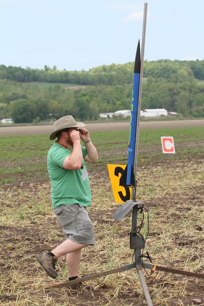
- Place rocket vertical in stand (see pic). This is the potentially unsafe step I'm not sure about with deployment electronics active. Maybe I should wait and just do this after the rocket is vertical?
- Turn on wifi switch and check easymega continuity indications
- Move shunts to disconnected, open wifi switch to easymega and turn off wifi switch itself, turn off PF CF or timers.
- Insert igniter, place on rail, and repeat above with 3rd stage.

Once both stages are on the rail:

- Turn on PF CF in 2nd stage and timers in the 3rd stage and verify continuity (gotta turn these on now if I want to stay off the ladder)
- Turn on Wifi switch power and verify Easymega does not turn on
- Folks back off, turn shunts to connected position
- Raise rocket, folks leave
- Turn on easymegas with wifi switches (hope I can hear that they turn on)
- Launch rocket

I have something of an advantage doing this at Balls because it is not necessary for people to be present to raise the rocket. Thus, activating deployment electronics with the rocket horizontal is not a safey issue. They also put me 2 miles from the flight line.

Jim

IMG_1312.jpg
 
Jim,

I think this is what I love about staging, I had to read that a few times to understand the proceedure.

So I assume the easymega is connected to the deployment charges? If so you could add the same switch or shunts to the deploment channels to remove the risk you are concerned about.

You are really testing the easymega at this point, which I agree with, but is there a reason the PF CF and timers need to be on outside of the easymega?

Those are my intital questions but I will take a look again when I get home from work.
 
Back
Top