


bandman444
Well-Known Member
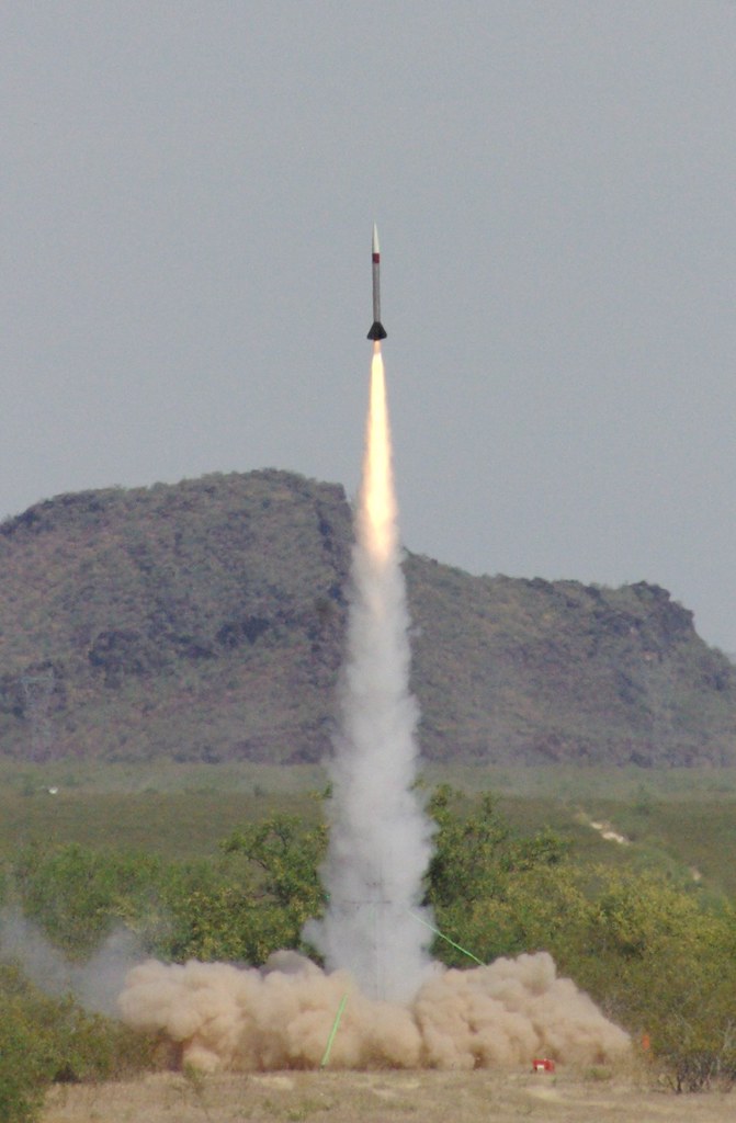
M3R is an extreme project with an extreme team of students from Embry-Riddle Aeronautical University in Prescott, Arizona, trying to learn what is possible from an engineering design and with limited university resources.
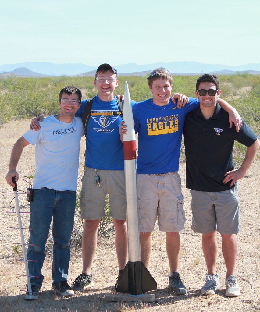
Let me introduce the team:
Chad Reinart (chadr77) - Team Lead
William Carpenter (RedMaxFlyer)
Daniel Dyck (Daniel777BD)
Cameron Kurtz
Julie Levitt
Bryce Chanes (Bandman444)
We can't start what is going to be a mega post without thanking the many individuals and groups that have supported us:
Embry-Riddle's Undergraduate Research Institute - Funding
Dr. Matt Pavlina - Project Advisor
Dr. Michael Fabian - Propulsion Advisor
Mr. Michael Brady - Director of Campus Safety
Mr. John Jerome - Campus Fire Safety Director
Scott Korsmier - motor design questions
Tripoli Phoenix - Launch site and FAA liaisons
The Eagle Space Flight Team - Lab-use and equipment
Eagle Aerospace - Lab-use and equipment
Now for the build thread!
Starting with the fin can fabrication.
Thanks to various aerospace donors, our campus has two freezers full of prepreg material. Carbon, fiberglass, bidirectional, unidirectional, just resin, it's all expired, but pretty much all still usable.
For those who are not familiar with preimpregnated cloth, it's the same cloth you would use for your regular layup, except the epoxy is already mixed in, but not cured. It remains uncured at cold temperatures (hence the freezer). When heated to specified temperature, at a specified rate, for a specified time, it flows and cures. This is done in a vacuum bagged setup so the fibers don't move around and the flowing epoxy can be well distributed during the cure.
To start the fin can we made a cylindrical tube of two wraps of carbon.
We started by taking a 98mm Trucore motor case as the mandrel and wrapping it in exactly one layer of release film held together by a long strip of kapton tape. The release film was held onto the mandrel by a strip of tape on the top and bottom. It is important to note that the release film was longer than the carbon part we intended to make and the tape was never covered either, this was to help facilitate easy removal after curing.

One of the great benefits of using prepreg is how easy it is to cut very precisely. This will be more apparent when we start doing the fin layers, but even getting a perfect rectangle was much easier than with dry cloth. I liken it to cutting thin leather. Pliable, yet stiff when cold. It grows to being slightly tacky as it warms up, another trait that will be important for the fin stock fabrication later on.

While a regular vacuum bag could have worked for this this lay up, we wanted to prevent the chance of wrinkles and also Chad had some heat shrink release tape that he purchased just for this kind of part. Starting below the part, I acted as a human lathe, rotating the part on a dowel while chad tried to lay down as consistent of a wrap as possible. This took some practice, but by half way down the tube Chad was laying down a nice wrap. Again, after wrapping past the part, a piece of kapton tape held it so our beautiful wrapping job wouldn't come off.
Because our on campus curing oven is only run during school hours, we had to put our oven-ready tube in the freezer till the next day.

In morning we get to put the tube in the oven. (A pretty big oven for such a small part, I know, but...that's what we have)

After the 5 hour baking process with a max temperature of 350F we were able to remove our cured tube. Removal of the heat shrink tape was painless but left a spiral of extra epoxy that squeezed out during the cure.

Chad enjoyed getting his photo taken while pulling the heat shrink tape.

Prior to sanding, the tube weighed only 73 grams and 0.021” thick. Which worked out to around 5 grams per inch.

A little bit of wet sanding removed those spirals and now we are ready to move onto the next step.

Fin preparation
For this extreme project we were pulling out on all the stops on having a beautiful and intentional airfoil. To do this we need to pick an airfoil, the NACA 64008, then represent that airfoil as a series of layers for us to cut. You could think about it a little like 3D printing, we started with a flat and thin carbon sheet, then added 6 progressively larger pieces that would form the foundation of the airfoil. To create the template shapes, we used a program called 123D to slice our 3D CATIA models.
To cut these pieces out, we made paper templates then used those to make aluminum templates which we would trace with a knife to get our pieces. Again we used the prepreg carbon as its tackiness would aide in the aligning process.
As I mentioned above, there are 6 unique shapes to cut out, and each fin gets two sets, that's 48 piece we needed to cut out, so we got to work!
We cooled down a steel sheet to cut on so that we could work with the carbon for as long as possible without it getting warm.

We cut out our airfoil plan on thin steel sheet scraps. Since we needed to make a lot of them, 8 of each carbon shape, the metal guides would be a lot more friendly than paper forms.

Let me introduce the team:
Chad Reinart (chadr77) - Team Lead
William Carpenter (RedMaxFlyer)
Daniel Dyck (Daniel777BD)
Cameron Kurtz
Julie Levitt
Bryce Chanes (Bandman444)
We can't start what is going to be a mega post without thanking the many individuals and groups that have supported us:
Embry-Riddle's Undergraduate Research Institute - Funding
Dr. Matt Pavlina - Project Advisor
Dr. Michael Fabian - Propulsion Advisor
Mr. Michael Brady - Director of Campus Safety
Mr. John Jerome - Campus Fire Safety Director
Scott Korsmier - motor design questions
Tripoli Phoenix - Launch site and FAA liaisons
The Eagle Space Flight Team - Lab-use and equipment
Eagle Aerospace - Lab-use and equipment
Now for the build thread!
Starting with the fin can fabrication.
Thanks to various aerospace donors, our campus has two freezers full of prepreg material. Carbon, fiberglass, bidirectional, unidirectional, just resin, it's all expired, but pretty much all still usable.
For those who are not familiar with preimpregnated cloth, it's the same cloth you would use for your regular layup, except the epoxy is already mixed in, but not cured. It remains uncured at cold temperatures (hence the freezer). When heated to specified temperature, at a specified rate, for a specified time, it flows and cures. This is done in a vacuum bagged setup so the fibers don't move around and the flowing epoxy can be well distributed during the cure.
To start the fin can we made a cylindrical tube of two wraps of carbon.
We started by taking a 98mm Trucore motor case as the mandrel and wrapping it in exactly one layer of release film held together by a long strip of kapton tape. The release film was held onto the mandrel by a strip of tape on the top and bottom. It is important to note that the release film was longer than the carbon part we intended to make and the tape was never covered either, this was to help facilitate easy removal after curing.
One of the great benefits of using prepreg is how easy it is to cut very precisely. This will be more apparent when we start doing the fin layers, but even getting a perfect rectangle was much easier than with dry cloth. I liken it to cutting thin leather. Pliable, yet stiff when cold. It grows to being slightly tacky as it warms up, another trait that will be important for the fin stock fabrication later on.
While a regular vacuum bag could have worked for this this lay up, we wanted to prevent the chance of wrinkles and also Chad had some heat shrink release tape that he purchased just for this kind of part. Starting below the part, I acted as a human lathe, rotating the part on a dowel while chad tried to lay down as consistent of a wrap as possible. This took some practice, but by half way down the tube Chad was laying down a nice wrap. Again, after wrapping past the part, a piece of kapton tape held it so our beautiful wrapping job wouldn't come off.
Because our on campus curing oven is only run during school hours, we had to put our oven-ready tube in the freezer till the next day.
In morning we get to put the tube in the oven. (A pretty big oven for such a small part, I know, but...that's what we have)
After the 5 hour baking process with a max temperature of 350F we were able to remove our cured tube. Removal of the heat shrink tape was painless but left a spiral of extra epoxy that squeezed out during the cure.
Chad enjoyed getting his photo taken while pulling the heat shrink tape.
Prior to sanding, the tube weighed only 73 grams and 0.021” thick. Which worked out to around 5 grams per inch.
A little bit of wet sanding removed those spirals and now we are ready to move onto the next step.
Fin preparation
For this extreme project we were pulling out on all the stops on having a beautiful and intentional airfoil. To do this we need to pick an airfoil, the NACA 64008, then represent that airfoil as a series of layers for us to cut. You could think about it a little like 3D printing, we started with a flat and thin carbon sheet, then added 6 progressively larger pieces that would form the foundation of the airfoil. To create the template shapes, we used a program called 123D to slice our 3D CATIA models.
To cut these pieces out, we made paper templates then used those to make aluminum templates which we would trace with a knife to get our pieces. Again we used the prepreg carbon as its tackiness would aide in the aligning process.
As I mentioned above, there are 6 unique shapes to cut out, and each fin gets two sets, that's 48 piece we needed to cut out, so we got to work!
We cooled down a steel sheet to cut on so that we could work with the carbon for as long as possible without it getting warm.
We cut out our airfoil plan on thin steel sheet scraps. Since we needed to make a lot of them, 8 of each carbon shape, the metal guides would be a lot more friendly than paper forms.
Last edited:


")


