Hey, I like feedback...
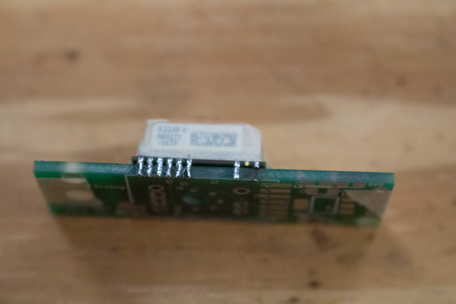
I kind of agonized over the header and the pads, I ended up putting in the header rather than something else (maybe a JST-XH, one of those little connectors) because it didn't require a pigtail to connect to the pairing cable. That would have run the cost up, for something that you're going to use a few times, maybe. Most people that I've spoken with change the frequency on their Eggfinders exactly ONCE... to "their" frequency/ID, then they leave it there. Considering that, the header/solder-pads was a reasonable choice. You'll notice that in the picture of the GPS glue joint there's no header... I removed it after I programmed it to make it easier to fit into a Dino Chutes 1" shock cord protector. Yes, it fits... along with a 300 mAH 2S LiPo.
I'll probably suggest that users put a toothpick into the "+" battery pad before they solder the diode, like I do with the TX's antenna hole before you solder the RF module's antenna pad. That should take care of any issues.