"Short and stubby rule" -- can someone explain it in pseudo-scientific terms?

The Rocketry Forum

Help Support The Rocketry Forum:

This site may earn a commission from merchant affiliate links, including eBay, Amazon, and others.
I just picked up a Warlock at LDRS today and am looking forward to the build.
Did you add any nose weight?
Would you mind sharing your RS or OR sim file so I can see what the zero-mass cone looks like?
I'd love to build this thing stock if possible.
I did the Minie Magg a few months ago and added about a pound a half to the nose. Now I'm wondering if that was even necessary.
I built a Warlock absolutely stock with TiteBond II for my L2 cert (No epoxy or FG reinforcement). With paint but w/o motor it weighs only 106 oz. It is stable without nose weight on any 38 mm motor with sufficient thrust: more than Mid-H impulse (>200 N) and average thrust >150 N (>200 N preferred).
 
Awesome.
I'd love to feel confident enough to do it all in Titebind II.
What motor did you fly it on for your L2?
 
I just picked up a Warlock at LDRS today and am looking forward to the build.
Did you add any nose weight?
Would you mind sharing your RS or OR sim file so I can see what the zero-mass cone looks like?
I'd love to build this thing stock if possible.
I did the Minie Magg a few months ago and added about a pound a half to the nose. Now I'm wondering if that was even necessary.

It's not a Warlock, but here is my Wastelander just to show you the zero mass cone. The cone is just a transition placed at the aft end. The forward end should be as small as you can get it, I think .001" is small as it goes. Aft end is diameter of body tube. Length is Pi x Diameter. Remember to override mass to zero (0).

View attachment Wastelander zero mass cone.ork

You can scale the entire rocket in this file and then just drag the cone to your Warlock.

Mikey D
 
Thanks. I'll give that a try.
EDIT: Thanks Mikey D. The zero-mass cone worked nicely. I'm getting 1.25 cal stability on a J425 now.
I asked Dave at Loc Precision whether nose weight was required and he says it should fly fine without nose weight.
 
So this thread got me thinking- and I have been staring at this on my desk for a few weeks now.
Im obviously thinking low and slow and using a 29mm motor. Just cant seem to wrap my hands around fin design yet- Im tempted to go Mega Mosquito style / thru wall style fin- I know Im gonna need the drag-
Suggestions welcome ??
9bm5pj.jpg
 
like his- just upsize the fins a tic - 3 layer style like the MM - THRU WALL Just upscale to the size of the original fin template outer sheet size .

20170410_152852.jpg
 
Can someone explain why we simulate stubby rockets with a massless cone protruding form the aft of the rocket (pointing toward the center of the aft end of the rocket). I assume that the idea is to model the airflow over a wide body as it moves, but wouldn't it make sense to model it with the cone pointed the other way (away from the aft end of the rocket)?
 
Can someone explain why we simulate stubby rockets with a massless cone protruding form the aft of the rocket (pointing toward the center of the aft end of the rocket). I assume that the idea is to model the airflow over a wide body as it moves, but wouldn't it make sense to model it with the cone pointed the other way (away from the aft end of the rocket)?

Essentially, the sims do not correctly calculate base drag. Base drag can significantly move the Cp. This method has been proven to work through calculation and many test flights to correct the sims.
 
Can someone explain why we simulate stubby rockets with a massless cone protruding form the aft of the rocket (pointing toward the center of the aft end of the rocket). I assume that the idea is to model the airflow over a wide body as it moves, but wouldn't it make sense to model it with the cone pointed the other way (away from the aft end of the rocket)?

Did you miss this post? Detailed analysis in the PDF. https://www.rocketryforum.com/showt...pseudo-scientific-terms&p=1669484#post1669484
 

Maybe I'm still missing something. I just want to know the story and reasoning behind the massless transition. I can't seem to find it in that article. But maybe the math is just over my head.

Bruce Levison's 1st Apogee newsletter on the subject says "Various aerodynamic texts confirm the fact that the dynamic Center-of-Pressure (CP) of flat plate lying perpendicular to a flow, lies behind the plate along its central axis, due to a base vortex that forms when the air begins flowing over its surface." It then shows an image of a plate with a cone pointing into its base.

I'm just wondering why the the shape of the base vortex is a cone pointing towards the flat body. It sure seams to me that the airflow would create a boat tail-like shape. But I'm a chemist--a far cry from an aerospace engineer.
 
It then shows an image of a plate with a cone pointing into its base.

I'm just wondering why the the shape of the base vortex is a cone pointing towards the flat body. It sure seams to me that the airflow would create a boat tail-like shape. But I'm a chemist--a far cry from an aerospace engineer.

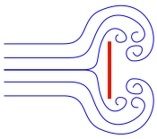
The cone isn't a representation of the vortex. Its just the trick in our barrowman sim programs that will Approximate similar drag.

A massless reducing transition (boat tail) will actually throw your CP forward because it will reduce the base vortices at the aft-end of your rocket.

This is a disk, not a tube, but you can get an inkling of the vorticity at play.
 
Maybe I'm still missing something. I just want to know the story and reasoning behind the massless transition. I can't seem to find it in that article. But maybe the math is just over my head.

Bruce Levison's 1st Apogee newsletter on the subject says "Various aerodynamic texts confirm the fact that the dynamic Center-of-Pressure (CP) of flat plate lying perpendicular to a flow, lies behind the plate along its central axis, due to a base vortex that forms when the air begins flowing over its surface." It then shows an image of a plate with a cone pointing into its base.

I'm just wondering why the the shape of the base vortex is a cone pointing towards the flat body. It sure seams to me that the airflow would create a boat tail-like shape. But I'm a chemist--a far cry from an aerospace engineer.

I think the answer is probably here, except that you need to order the CD to get the rest of the article. My guess is that the air getting trapped between the aft end of the rocket and the sides of the triangle create the additional drag, whereas a triangle that is shaped more like a tailcone would not create as much drag.
 
A tail cone (big end in front) would be destabilizing whereas a nose cone is stabilizing. I don't think the 'phantom cone' method is necessarily an great simulation of base drag. Rather, Bruce came up with a approximation using a design component that could actually be placed in, and recognized by, RockSim.
 
Thanks, guys. It makes sense that a phantom tail cone would actually have the opposite effect. So it sounds like the backwards tail cone is more of a way to hack Rocksim and OpenRocket. I've done it before, so I can attest that it works. It just aways seemed weird to me.
 
A tail cone (big end in front) would be destabilizing whereas a nose cone is stabilizing. I don't think the 'phantom cone' method is necessarily an great simulation of base drag. Rather, Bruce came up with a approximation using a design component that could actually be placed in, and recognized by, RockSim.

Dick, It works as evidenced by all the successful flights based on sims using this method. That said, it would be great if there was a way get the programs to calculate this correctly with using a fabrication non component
 
Dick, It works as evidenced by all the successful flights based on sims using this method. That said, it would be great if there was a way get the programs to calculate this correctly with using a fabrication non component

I have used in many times. I was just saying it is a hack to get RockSim to work, it does not actually model any turbulence. You can't worry about what the airflow over the phantom cone is doing. It just fakes the simulator out.
 
Back
Top