


- Joined
- Jul 15, 2015
- Messages
- 3,948
- Reaction score
- 2,685
Still building?


Ok, back to it.
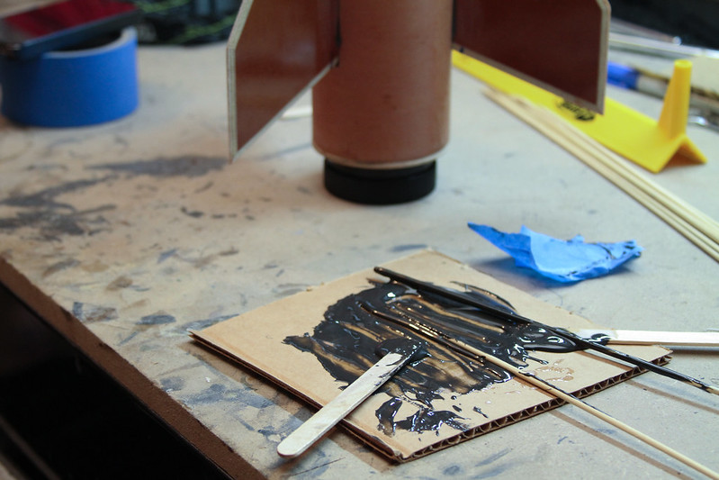
Once the Scarab has its fins tacked up, internal filets will be applied using Rocketpoxy. I'm a little worried that the hardener has become even more thick over time. Is there a way to thin it down or is that a good idea?

After a day, it was time to take off the Wild Thang retainer and rear centering ring but the retainer didn't budge at first. I had been careful to not put any epoxy on the last quarter inch of the fins just in case but apparently some little bit must have made it down there. Thankfully, a light tap on the bench top broke the retainer free. The screws were then inserted in the previously drilled centering ring holes and with a twist and some wiggling, the ring came out as well - whew!
View attachment 301982
As the Scarab gets its fins next, there is a question on the best method to use for internal fillets. When first attempted on a Vulcanite (see post #34 https://www.rocketryforum.com/showt...zon-build-challenge/page2&highlight=vulcanite), slipping epoxy through the narrow passages between fins was messy and difficult at best. There is two part foam or maybe gorilla glue that could be an alternate way of doing it. But would that be as strong? Anyone have suggestions here?


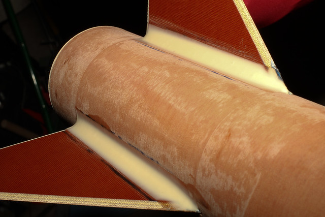
 One downside of translucent tubing is that any mistake is going to show through.

Went to add external fillets to the Scarab fins only to have them snap off where they had been epoxied to the motor tube. As they were all about the same to dislodge, I suspect the 30-minute epoxy used had had enough time to start to set up and therefore did not fully adhere to the motor tube. The fin slots in the booster tube were also really narrow so maybe not enough epoxy got through to create enough surface area for a strong bond. I may try first sliding in some epoxy from the bottom of the booster tube to coat the areas on the motor tube below the fin slots.

On a rocket of this size the best option for the internal filets of to inject them. It is much easier, and will provide a more consistent result.


As the Scarab gets its fins next, there is a question on the best method to use for internal fillets. When first attempted on a Vulcanite (see post #34 https://www.rocketryforum.com/showt...zon-build-challenge/page2&highlight=vulcanite), slipping epoxy through the narrow passages between fins was messy and difficult at best. There is two part foam or maybe gorilla glue that could be an alternate way of doing it. But would that be as strong? Anyone have suggestions here?
Placement of the Schurter switch on the sled puts it up high and at one end. For a shorter av bay, there is no way to line the switch up with the vent band. I would either need to cut the sled down a bunch or drill a hole through both the sustainer and av bay tubes to get a screwdriver in and turn on the electronics before launch.
What have others done in this situation?


Enter your email address to join:


