DavidMcCann
Well-Known Member
- Joined
- May 15, 2016
- Messages
- 2,656
- Reaction score
- 180
not a bad idea... toasty rear-ends are no fun


")
I know you'll come up with something cool for the fins, but to share: I built a 4" cardboard rocket and Surface mounted the fins...with wood glue....poorly.... many flights, and even had a chute float away (opps) and it tomahawked a fin into the ground. All fins still on
You should really try building at least one kit according to the instructions provided rather than re-inventing the wheel and calling it "fire". Just saying.
No can do. I've spent my life in R&D aerospace related work and have become 'tainted' with the results of such. Heck, I can't even follow the given instructions on a box of 'Hamburger Helper' anymore! :lol:
So why do you keep asking for people's input, and then not following any advice given? Thousands of people here have built these kits according to instructions with nary a problem. Just sayin'...
Lol, so, you send me threatening private messages now, just because I point out the same fact that others here have pointed out? I asked a simple question and made a simple statement. Telling me that I can't comment on "your" threads is childish. Now you really don't want to know what I think of you...
I never once attacked you. And now you've resorted to name calling. Shame on you View attachment 297553

You said it correctly, Jim! Good explanation of why the lower section of the e-bay needs to be at least the body tube diameter. I'll be using shear pins up top.
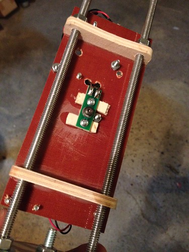
I 'finally' got around to examining the RRC3's (and also read the instructions, LOL). Taking your advice, I drilled three 3/16" dia holes for porting. I also noticed that your instructions say 3/16" for 4"X12" bays. My e-bay has only 7.5" of internal length between the bulkhead plates. Is 3/16" still okay with this shorter length? I can fill them in and use smaller holes if need be.
I cheated on laying out the porting holes. I shoved the e-bay up the rear of my unstarted DX3 and used the fin slots to equally space out the ports. I 'knew' that DX3 would come in handy for 'something'! :wink:
View attachment 297593
. Is 3/16" still okay with this shorter length? I can fill them in and use smaller holes if need be.
I cheated on laying out the porting holes. I shoved the e-bay up the rear of my unstarted DX3 and used the fin slots to equally space out the ports. I 'knew' that DX3 would come in handy for 'something'! :wink:
View attachment 297593
Yes you'll be fine. As I mentioned in the PM, when these sizes were recommended in the manual, it took into consideration a variety of lengths & was approved by Jim Amos.
Might I suggest:
Coat the outside of your coupler with a lightly thinned layer of epoxy. It will soak in & harden the exterior, also eliminating the "fuzzies" that build up after several flights.
You will notice a marked difference in how much better it slips in/out after a light sanding. While at it, do same to BP's
Yes, that little "tip" of using fincan slots to mark for 3 even points of reference is one of my favorites first tip I put in instructions.
Just a comment having no particular bearing on anything......... As time goes on and experience is gained, most find eliminating as much as possible, simplifying to the max, saving weight where ever possible....is the mantra of performance and successful flight.
That being said, most of us starting out, go the opposite direction, till reality sets in....... "less is Mo' betta" LOL
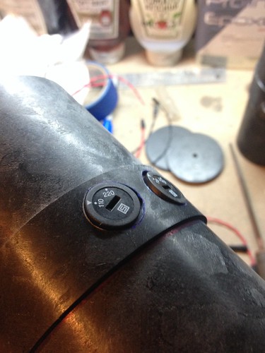
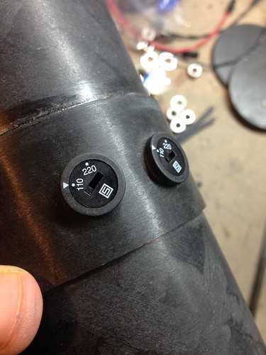
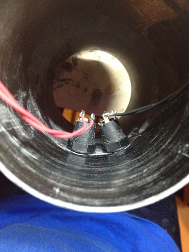
I've done the twist the wires together and tape them to the side of the rocket. It's not elegant, but it works. Fishing for switches sucks. Externally mounted switches are nice.

Enter your email address to join:


