Two stage rocket - Stage connection question

The Rocketry Forum

Help Support The Rocketry Forum:

This site may earn a commission from merchant affiliate links, including eBay, Amazon, and others.

Salvage-1

Certified
Joined
Mar 17, 2012
Messages
2,688
Reaction score
41
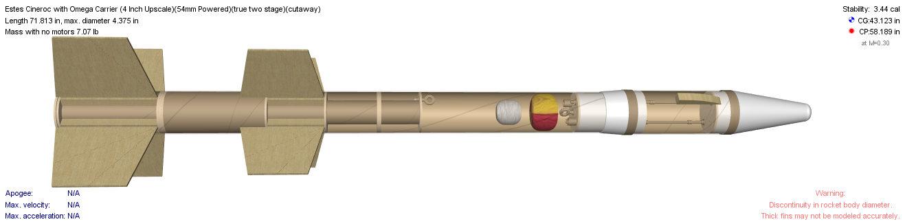
I am about to start building a two stage rocket, and in the designs I have the sustainer with a coupler that slots into the booster.
On a lot of two stage builds that I see on here, by some quite talented people, I see that they have the interstage where the booster has a coupler that slots into the sustainer.

Why are people doing it this way? It doesnt make sense to me. I thought that the open base of the sustainer would add a lot to the base drag, and that the coupler in the sustainer idea would reduce it and would allow the fins to be a little farther back.

I would love to hear peoples opinion on this. What are the advantages/disadvantages that you see in either design?

My Idea

Flying wallabies.jpg

Flying Wallabies 2.jpg
 
Taking the interstage coupler with the sustainer does make sense from a base drag perspective. It does mean you have to make other provisions if you want avionics in the booster and if you want something sealing the top of booster airframe after separation.

Edit.
Ok, now I see... You still have the remaining part of the interstage coupler with avionics in the booster. The transfer of force up the stack is limited to the outer tube in that configuration because the nozzle sticks out and you need a little space below the nozzle to the interstage coupler bulkhead. When the inner coupler slots into the sustainer, it can also transfer force to a centering ring just aft of the sustainer fins. When everything interlocks that way, the force is distributed over more area and the stack is more rigid. So... Maybe you get around that by a short length of inner coupler that sits between the bulkhead and sustainer inner coupler. Then force can be transferred up the inner coupler as well.
 
Last edited:
....<snip>..... I see that they have the interstage where the booster has a coupler that slots into the sustainer.
Why are people doing it this way? It doesnt make sense to me. I thought that the open base of the sustainer would add a lot to the base drag, and that the coupler in the sustainer idea would reduce it and would allow the fins to be a little farther back.
I would love to hear peoples opinion on this. What are the advantages/disadvantages that you see in either design?
My Idea
View attachment 295550

"I thought that the open base of the sustainer would add a lot to the base drag, and that the coupler in the sustainer idea would reduce it and would allow the fins to be a little farther back"

Most of the designs I've seen (including the ones I've done) merely omit the entire thru the wall fin root on the sustainer fins to allow the coupler of the booster/interstage to plug into the rear of the sustainer, and not run into fin roots inside the sustainer airframe, or require that the fins be farther ahead. So there really isn't a penalty where you locate the fins the sustainer. You take out sustainer fin root material ....to allow for the booster coupler to plug in.

Figure 3 in this instruction sheet for a two stage Aerobe hi shows this clearly:
https://www.cosmodromerocketry.com/Instructions/AerobeeHi/instructions_ABHI2.pdf

In this scenario - base of the sustainer is open.......so I'm not sure I understand your point there about the relationship to base drag.
Some extension of the airframe behind the sustainer fins might jive with typical drag reduction ideas.
I think that can still be done with a coupler in the booster section.
Not sure from your drawing how long the coupler is - or where it is.
Question - extending a coupler from the sustainer rearward into the booster gains what exactly? By the same token I'm not sure if it loses anything either - but doesn't the motor have to extend rearward with the coupler, to avoid motor exhaust burning the inside ? That coupler stays with the sustainer. The other way...with the coupler on the booster....it goes away immediately with the booster section upon separation.
 
Last edited:
My thoughts were that an open base of any sort increases the base drag compared to having a centering ring at the rear of the rocket. There would be such a gap between the motor mount and the airframe if the coupler/interstage was connected to the booster and slotted into the sustainer. It is probably not that much of a concern though.

(for a 3" airframe) If I glue a coupler into the rear of the sustainer with 3" poking out, move the engine mount back 3", centering ring at the bottom of the coupler and locate the fins say 1/2" forward of the rear of the sustainer airframe; this would allow me to slot the coupler into the top of the booster airframe. I am planning on having a bulkhead 1" lower than the rear of the engine in the booster incase drag separation doesnt happen and it has to rely on separation charge; protecting chute.

My thoughts are that I can then carry all the electronics needed for separation event and staging in the sustainer. Running everything in a conduit that runs along the MMT and comes out next to the retention.
It also means that the rear of the rocket has a bulkhead and while not a tailcone, it won't have quite as much of a drag issue as leaving just a gap between MMT and body tube on the 'traditional' way.

I have got a couple of two stage kits here and they both have the booster slotting into the sustainer, I was just wondering why people are using this menthod?
 
Last edited:
<snip>The transfer of force up the stack is limited to the outer tube in that configuration because the nozzle sticks out and you need a little space below the nozzle to the interstage coupler bulkhead. When the inner coupler slots into the sustainer, it can also transfer force to a centering ring just aft of the sustainer fins. When everything interlocks that way, the force is distributed over more area and the stack is more rigid. So... Maybe you get around that by a short length of inner coupler that sits between the bulkhead and sustainer inner coupler. Then force can be transferred up the inner coupler as well.

The plan is to have a stepped centering ring at the rear of the coupler. This, bonded to the coupler and the motor mount should lock everything together and distribute the force of the motor equally through the coupler (and then to the main body tube) and the MMT.

As I see it, if the coupler is in the top of the booster, and (say for a 3" rocket) slots 3" into the bottom of the sustainer, then the logical place for the aft most centering ring on the sustainer would be 3" from the base of the rocket. This would mean that the motor mount should then stick out 3" from the rear of the aft centering ring so it is level with or lower than the aft end of the sustainer body tube and therefore the first point which the MMT can transfer the force to the body tube, etc would be at that aft centering ring.

Again just throwing this out to see if anyone has any thoughts on the differences between these two methods.
 
The plan is to have a stepped centering ring at the rear of the coupler. This, bonded to the coupler and the motor mount should lock everything together and distribute the force of the motor equally through the coupler (and then to the main body tube) and the MMT
Not sure I understand that - is that what is in the second design picture?

As I see it, if the coupler is in the top of the booster, and (say for a 3" rocket) slots 3" into the bottom of the sustainer, then the logical place for the aft most centering ring on the sustainer would be 3" from the base of the rocket. This would mean that the mount should then stick out 3" from the rear of the aft centering ring so it is level with or lower than the aft end of the sustainer body tube and therefore the first point which the MMT can transfer the force to the body tube, etc would be at that aft centering ring.
Again just throwing this out to see if anyone has any thoughts on the differences between these two methods.

Coupler on an inter stage on the top of the booster fin can ....I think that is what most of the 2", 3", and 4 " two stage projects I've seen - have.
I've scratch built three like that (all 3" and 4" diam.) and am working on a fourth - modified PML 3" dia. Quantum Leap that has the same thing.
All basically up scaled concepts from the previously mentioned 2.5 " Cosmodrome Aerobee Hi kit, and do not see a problem, nor an advantage to doing it otherwise.

two stage 1.jpg two stage 2.jpg two stage 3.jpg two stage 4.jpg
 
Last edited:
The base drag won't be appreciably greater with a void vs. centering ring on the aft end, but skin drag will be greater if there is a step in the airframe from the coupler.

Sleeving the interstage into the aft of the sustainer has a strength benefit if you can size the sleeve where the OD matches the ID of the sustainer airframe, AND the ID matches the OD of the motor tube.
 
The base drag won't be appreciably greater with a void vs. centering ring on the aft end, but skin drag will be greater if there is a step in the airframe from the coupler..

Hmmm good observation there. Drag working on the entire outside surface of the rocket.
 
I've always built mine where the interstage coupler[I/S] slides into the sustainer & acts like a nosecone for the booster.

My sustainers are built so the motors mount is always flush [or close] to rear of airframe, just like a normal rocket.
As such there is no "open" rear, the only gap is enough so a coupler will fit between the airframe and motor/retention.
My fins are always to rear, unless using motor as coupler.

DSCN2156.jpg DSCN5314.jpg DSCN5315.jpg


I use separation charge at motor burn out, do not want to drag booster along until sustainer fires.

Light booster.....motor burn out, fire separation......sustainer coast, unencumbered, after several seconds...sustainer fires.

I would not want a coupler hanging out the rear of sustainer, unless I'm missing something here. Don't quite follow the logic of your other method????
 
Last edited:
I use a system like the Nike-Cajun where the forward part of the booster coupler seats into the nozzle of the sustainer. works nicely, and drag separates without any charges and as soon as the booster momentum is overcome by the booster drag.

It does freak folks out sometimes, but under acceleration it locks down nicely. physics is great!

ImageUploadedByRocketry Forum1467605847.175474.jpgImageUploadedByRocketry Forum1467605869.843824.jpg
 
I also use kapton and copper tape to run the "starter" wires down the min diameter body or motor casing. 1/4 copper tape can carry plenty of current to start the motor.
 
For those of you who use a separation charge to jettison the booster, do you just use the motor ejection charge with a short delay? Is there any chance of a charge like that knocking the sustainer off of a vertical fight trajectory?

I'm in the planning stages for a 3" Punisher(ish) booster with a Punisher Sport sustainer. I'll need to build a custom ISC, so this thread is helpful. Thanks.
 
Last edited:
I use a system like the Nike-Cajun where the forward part of the booster coupler seats into the nozzle of the sustainer. works nicely, and drag separates without any charges and as soon as the booster momentum is overcome by the booster drag.

It does freak folks out sometimes, but under acceleration it locks down nicely. physics is great!

View attachment 295941View attachment 295942

That's really interesting.

So no lateral forces upset the connection...the forward thrust keeps the thing together...?
 
For those of you who use a separation charge to jettison the booster, do you just use the motor ejection charge with a short delay? Is there any chance of a charge like that knocking the sustainer off of a vertical fight trajectory?

.

I have not experienced sustainer ''knocked" off vertical from charge, you only need a tiny charge. I suppose if large enough, it could happen.
You cannot use motor eject to separate booster/sustainer without blowing the I/S off. A more logical way is contain a timer/accelerometer/ altimeter in the I/S. At motor burn out small charge [1/2 gram or less] fires to separate the booster/sustainer.

Charge is located on top/inside bulk plate of I/S, nozzle cap/wooden disc is placed on top of charge to protect the e-match inside of Sust. motor from damage or accidental premature firing.

My I/S doubles as nosecone for the booster & stays in place after separation charge fire, until booster reaches its apogee, when altimeter or timer fires for chute release the I/S pulls out the main.

My I/S is a very good "slip" fit. At booster burn out it will separate like a boosted dart. But you must also accept for "dynamics" of flight. Wind shear/ off vertical flight/etc. may cause some binding/tension of I/S joints and separation charge give it some help....lol

Of course if altitude is not your thing, many just do separation of booster/sustainer when sustain ignition occurs. Then you are dragging the booster along for the ride, till ignition. Actually not a bad thing for first few flights, then attempt dealing with separation charge, after mastering just getting a 2-stage to work.
 
Last edited:
I use a system like the Nike-Cajun where the forward part of the booster coupler seats into the nozzle of the sustainer. works nicely, and drag separates without any charges and as soon as the booster momentum is overcome by the booster drag.

It does freak folks out sometimes, but under acceleration it locks down nicely. physics is great!

View attachment 295941View attachment 295942


Does the outer aluminum "lip" also lock into rear of sustainer?
 
That's really interesting.

So no lateral forces upset the connection...the forward thrust keeps the thing together...?

Yes, that's been my experience. I have flown this multiple times on M1315 to M1297 flights and it works great. I did a bunch of lower power testing prior to that, perhaps 3 other flights, and the arrangement works. I also have a friend that uses the reverse combination with a tailcone and matching receiver on the booster. Once you're under acceleration, the cone you see in the picture seats into the nozzle and any lateral forces don't affect it. BTW, that cone is a cast JB-weld component. I do also use an anti-rotation feature in case any vibrations cause the stages to "walk" in rotation.

Granted, you do have to do some engineering calculations to make sure that you don't break something. The load path for the sustainer is all through the nozzle and liner. In my configuration, I have about a 3:1 safety margin on the compression strength of the components. The airframe and fin drag forces are transferred to the motor casing by a forward retainer (Aeropack). The motor itself sits on the booster.
 
Does the outer aluminum "lip" also lock into rear of sustainer?

There's no aluminum in this system. The gray stuff you see is JB Weld, cast molded to the nozzle.

I just realized that the photo I uploaded is the prior version, that outer JB Weld casting is no longer in the system. After some calculations, I decided that I didn't need it and it was creating a compliance issue with the tolerances in motor/reload builds. I now use this version (see below) that only has the nozzle cone. That slot in the cone is for the "starter" wires to go up into the motor.ImageUploadedByRocketry Forum1467660243.213286.jpg
 
I would love to hear peoples opinion on this. What are the advantages/disadvantages that you see in either design?

There are other possible options for interstage coupling.

For example, A group I'm a member of designed and built a WAC Corporal including the Tiny Tim booster. We did our best to come up with an interstage coupler that mimicked the original setup as close as we could. What we came up with is a nose cone for the booster that incorporates a ring slightly above the tip of the nosecone supported by 3 rods that extend into the nosecone below and also run up into the sustainer into friction fit tubes that allow the sustainer to slide up and down freely (with a little bit of resistance). The idea is that while under boost, the sustainer will be pinned to the top of the booster by drag and g force. As soon as the booster motor burns out, the sustainer is free to come off of the booster. Once the sustainer motor fires, if it's still attached to the booster, it will separate immediately from the force of the sustainer motor firing and the sustainer will then continue on it's way. We've been flying that rocket and configuration now (with new and improved versions of both the sustainer and the booster) for over 10 years and have never had any problem with separation. Once the sustainer fires, it WILL separate from the booster.

The original WAC Corporal, used almost the same setup with the exception being that they didn't have the slip tubes and extended rods that we are using. They used explosive bolts secured to the bottom of the sustainer. In addition, after we did extensive research on the rocket and how it was flown, we found that the sustainer motor was actually fired at almost the same time as the booster was fired. This was done deliberately to provide stability to the flight stack from the sustainer motors exhaust. The nose cone of the booster resembles a squat wide cone with the ring floating just above the tip of the nosecone. the ring was secured to the bottom of the sustainer as I indicated earlier with explosive bolt that were blown shortly after the booster burned out. The sustainer motor was a longer burn than the booster and once separation occurs will continue to fire and accelerate the sustainer to altitude. We couldn't use explosive bolts on our version, so we opted to extend the ring support rods into the sustainer to support and align the sustainer on the top of the booster. The booster nose cone was machined out of aluminum as was the ring and the rods. Airframe is approx 4.5" in diameter (both booster and sustainer) and the stack is about 11 feet tall. We've extended both the booster and sustainer over the years to accommodate electronics and chutes and so on so it's no longer to scale. We've had it up to 14,000 feet or so on an L2200 booster and L850 sustainer. Our last flight attempted a research M in the booster and the L-850 in the sustainer if I remember correctly. Unfortunately, the booster motor failed within seconds of liftoff due to a burn though in the motor case near the forward closure, and when the sustainer fired it was more horizontal than vertical and wound up 2.5 miles down range. It has since been repaired and is waiting flight likely on an L2200/M something flight that should put it into the mid 20,000 foot range!

Jeff Moore
BORG - Bend Oregon Rocketry Group
 
There's no aluminum in this system. The gray stuff you see is JB Weld, cast molded to the nozzle.

I just realized that the photo I uploaded is the prior version, that outer JB Weld casting is no longer in the system. After some calculations, I decided that I didn't need it and it was creating a compliance issue with the tolerances in motor/reload builds. I now use this version (see below) that only has the nozzle cone. That slot in the cone is for the "starter" wires to go up into the motor.View attachment 295997

A few weeks ago, I was "pouring" a nozzle cap that would cover a sustainer motor nozzle during the separation charge. I got to thinking about trying something similar, but I think I would do it with the acceleration forces against the motor or airframe and not entirely up through the nozzle. It looks like your design would do that? Am i missing something?

The other thing that occurred to me is that sometimes my two stage designs don't want to drag separate. It's always close - plus or minus a relatively small force.

Jim
 

Attachments

  • IMG_0828.jpg
    IMG_0828.jpg
    105.5 KB · Views: 143
  • IMG_0831.jpg
    IMG_0831.jpg
    92 KB · Views: 149
...... What we came up with is a nose cone for the booster that incorporates a ring slightly above the tip of the nosecone supported by 3 rods that extend into the nosecone below and also run up into the sustainer into friction fit tubes that allow the sustainer to slide up and down freely (with a little bit of resistance). Jeff Moore
BORG - Bend Oregon Rocketry Group

I think I did something similar to what you described, but the ring has a tube coupler that goes into the sustainer, along with three tubes that three rods that extend from the booster nose cone slide into.

two stage 4.jpg[
 
Last edited:
I think I did something similar to what you described, but the ring has a tube coupler that goes into the sustainer, along with three tubes that three rods that extend from the booster nose cone slide into.

View attachment 296004[

In our design, the nose cone is shorter and the rods extend nearly a foot into the sustainer. It's all machined aluminum and probable weighs in at 3 - 5 pounds. If I remember correctly, the slip tubes in the sustainer are also metal and we ran one additional tube all the way up to the top of the motor mount assembly in the sustainer, so that we could provide wiring to fire the sustainer motor from it's own ebay.

The coupling set up works great - we've had no issue other than we don't always get drag separation, but once the sustainer motor fires, there WILL be separation!

I have another project I'm in the design stages on. That will be a boosted dart. The dart, will have a full tail cone that will nest in the nosecone of the booster. That will eliminate base drag on the dart and hopefully provide a significant boost to the darts' performance. We will see. :) I'm shooting for 23 miles altitude or so (approx 125,000 ft).

Jeff Moore
BORG
 
Last edited:
I've been using the separation charge with no issues.
The last flight was at URRF 3 with a Wildman jr 2 stage stack.
Booster was a 4 grain 38 mm EX motor staging to an AT I 59.
I wired the separation charge in parallel to the upper stage igniter.
It only uses about 0.8 gm of BP.

JD
 
I've been using the separation charge with no issues.
The last flight was at URRF 3 with a Wildman jr 2 stage stack.
Booster was a 4 grain 38 mm EX motor staging to an AT I 59.
I wired the separation charge in parallel to the upper stage igniter.
It only uses about 0.8 gm of BP.

JD

Did you vent the sustainer motor to the outside somehow to prevent the pressure of the BP from chuffing the motor? Or is it even necessary, given the relatively fast pressure spike compared to the longer time that it takes to ignite the motor?
 
Yes, I did drill 1 x 1/8 or 5/32" hole for ventilation.
The sustainer motor nozzle was taped off, but I really wasn't concerned with that aspect of it.

The only other mods I did to this kit was:
cut down the booster by 5"; and added an Alt-bay just above the top of the motor tube ( in the sustainer section) for ignition timer.
Timer was set for 0.7 sec after burnout.
Booster has a Alt-bay in the inter-stage coupler; a Perfect Flight SL CF to be exact (due to it's small size).

I've flown this rocket in it's 2 stage configuration 3 times.
The first one; had ignition issues, the last 2 were perfect.
The booster was purchased as a Wildman jr alone and later added the 2 stage upgrade from another TRF member.


JD
 
Last edited:
Ok... I too am thinking about a 2 stage HPR rocket.


I'm really uncertain about how to manage the booster separation, and upper stage ignition. Do most 2 stage HPR rockets need 4 altimeters to ensure safe flying?

My thoughts go like this.

In its true two stage configuration I would use an interstage coupler that runs from the back of the sustainer aft CR. to the front of the fwd CR (well, locking ring actually) on the booster.

Inside the interstage coupler, there would be an AV bay that would house at least one (maybe two) altimeters, and their batteries. On the forward side of the AV bay would be a charge for each altimeter, and these would be set to separate the booster from the sustainer upon the booster's motor burnout. On the back side of the AV bay would be two other charges, as well as the shock cord and parachute to bring the booster in safely (the .ork sim has the booster coming in at about 2 lbs (not including motor casing)). Those charges would go off a moment or so after the forward charges fire, thus popping the interstage coupler off the booster and deploying the laundry.

After the booster separates, the altimeter(s?) in the fwd AV Bay (simulated Cineroc) would airstart the sustainer's motor as long as the rocket is still within acceptable margins from vertical. How to connect the AV bay in the Cineroc to the igniter(s) in the motor... unknown. I like the sound of the copper tape someone mentioned. Another idea would be to route a conduit for wires... However, what's to prevent the wires from snagging and holding the rocket together? I really don't want to put an AV bay down in and around the fin can, as accessing it would likely be a Royal PITA since the MMT is designed to be removable (to facilitate shipping it w/o fins attached), and any hatches would likely prevent it from sliding out.

Now, what if the rocket (for some odd reason) were to be outside of the acceptable margins from vertical? I don't know thing one about altimeters, or airstarts. How do you prevent a lawn dart if the worst should happen (say the sustainer fails to ignite)? I'm guessing that a barometric altimeter would sense the rocket has reached (likely exceeded) apogee, and fire, even if the rocket is still traveling at a higher speed than desired. Would an altimeter that doesn't use barometric pressure be able to sense the rocket is now heading for the ground? I'd much rather risk a zipper, and a shredded parachute, than have a ballistic return of a streamlined shape.

Thanks!
Jim
 
Last edited:
Ok... I too am thinking about a 2 stage HPR rocket.

.....

Now, what if the rocket (for some odd reason) were to be outside of the acceptable margins from vertical? I don't know thing one about altimeters, or airstarts. How do you prevent a lawn dart if the worst should happen (say the sustainer fails to ignite)? I'm guessing that a barometric altimeter would sense the rocket has reached (likely exceeded) apogee, and fire, even if the rocket is still traveling at a higher speed than desired. Would an altimeter that doesn't use barometric pressure be able to sense the rocket is now heading for the ground? I'd much rather risk a zipper, and a shredded parachute, than have a ballistic return of a streamlined shape.

Thanks!
Jim

Ahhh.... yes... been there done that.

You need a tilt meter that only allows the airstarts to fire if the rocket is less than x degrees from the vertical.

Or

A TeleMega, which will do everything that you need (and log it, and let you GPS track it, and stream data to your Android in real time... etc)
It was also my "need to get" after the "been there done that".
Now that I have one, back to two stage and clusters.
 
Thanks Rob,

Ok... So, presuming I got the Telemega... How many of them would I need? One for the Booster, one for the Sustainer? Or would it be in the sustainer, and linked somehow to something that would eject the booster (while deploying the parachute), then ignite the sustainer?
 
I am just planning motor deploy or DD in booster, with all major electronics in the sustainer. There will be conduits running down from the sustainer AV bay for the booster / sustainer separation charge and sustainer ignitor. In the past I have has JST connectors in the lower section of the sustainer that would pull apart easily when the sustainer did apogee deployment.
 
I am just planning motor deploy or DD in booster, with all major electronics in the sustainer. There will be conduits running down from the sustainer AV bay for the booster / sustainer separation charge and sustainer ignitor. In the past I have has JST connectors in the lower section of the sustainer that would pull apart easily when the sustainer did apogee deployment.

Any chance I could see some photos of your conduits and methods of wiring for the booster sep/airstart? My AV bay is planned for the nosecone. Where's yours?

Thanks!
Jim
 
Back
Top