Going for 100,000 Feet

The Rocketry Forum

Help Support The Rocketry Forum:

This site may earn a commission from merchant affiliate links, including eBay, Amazon, and others.
Does thrust change during that period?

You didn't imply anything; you flat out stated it wasn't possible. If thrust doesn't change during that time and if thrust is insufficient to overcome the significant increase in drag that takes place at that velocity, it's probable. It's just terminal velocity.


[emoji1010] Steve Shannon [emoji1010]
 
Last edited:
Rockets with long burn motors can maintain a nearly constant speed for a long time just below Mach. If the CD increases rapidly as it approaches M1 velocity will stabilize. Speed will increase as air density goes down with altitude.
I did End burn second stages that the booster took to .9 and the velocity remained constant for the 20 second burn.
 
Attached are the Open Rocket files. For some reason the Rocketry Forum doesn't like RASA files. There are several motor configurations and sims for each.

Someone private-messaged me and asked for them, but the e-mail bounced back as undeliverable.
 
Rockets with long burn motors can maintain a nearly constant speed for a long time just below Mach. If the CD increases rapidly as it approaches M1 velocity will stabilize. Speed will increase as air density goes down with altitude.
I did End burn second stages that the booster took to .9 and the velocity remained constant for the 20 second burn.

I can see your point but the issue I have is this. in the sim with Re... I used a CTI K2045 motor that I know pushed a small 3" 5-lb. rocket to Mach 1.45. I shredded the rocket on a K740 and the sim for that flight was Mach 1.56. Re weighs 7.81 lbs. at launch but is max. 2" in diameter. The 38mm sustainer weighs 3.39 lbs. The OR sim says that with a K740 (21.3:1 Thrust/Weight Ratio) booster and a J530 (35:1 Thurs-Weight Ratio) should top out at Mach 3.08. I find that a little hard to believe, but past Mach 2 should be possible with this combination.

RASA says it tops out at Mach 1.01 - Both the top speed of the booster stage and the sustainer stage are equal. Pretty weird considering the rocket is moving well over 450 MPH in this sim when the sustainer motor ignites, the sustainer has a much lower CD, and the thrust-weight ratio of the Sustainer is half again higher than during the booster stage.

One of these two sims is dreadfully wrong, but having seen a J530 push a Mad Cow FG Arcas (weight just over 5 lbs. 2.63" airframe with the older thicker-walled airframe) to Mach 1.14 WITHOUT a booster, my money says that the OR file is closer to being right.

I'm not trying to be critical of RASAero II here. I am just trying to figure out why in 3 sims that were all entered the same way do two equal out well and one goes completely out of whack.

Re J530-K740 Sim RASA.jpg Re J530-K740 Sim.jpg
 
Last edited:
[emoji1010] Steve Shannon [emoji1010]

Accepted, and I stand corrected. I don't want to argue the point. In these scenarios though, and if you look at all 4 of the sims I did with different motor variations, the likelihood of all of them coming within .02 -.03% of each other at top speed is highly improbable, including one that was intentionally a much stronger combination than the other three.
 
Yes it does, but as long as thrust exceeds weight acceleration should continue. The boosters are very light.

Only in a vacuum. In atmosphere acceleration will only continue as long as thrust exceeds weight plus drag. Drag goes up very steeply just before Mach.

b7a7c479f8e824077dc26e695a2b61cf.jpg
 
In RASA There is no way I can see to delay separation. Maybe there is a way I haven't learned yet.

That being said, I started completely from scratch with the Re sim in RASA. I did nothing differently than I did before, but now the simmed altitude comes within about 5% of Open Rocket. I have no idea what I did wrong the last time. Maybe the last file was corrupted. AS my computer engineer son would have put it..."The problem could have existed somewhere between the chair and the keyboard."

But now I am pretty sure I am going to need a 40K or 50K waiver to fly Re. RASA Simmed altitude is about 40,700' and OR altitude is about 42,300. Top speed was Mach 2.57. OR was Mach 2.66.

Throughout this process I have found you still need both sets of software. Since OR allows you to add electronics, includes motor weights in its files, and includes most of the details needed to build a rocket (except for some reason rail buttons), Then you can design the rocket, see how the components impacts CG and weight, then change your weight and CG numbers in RASA, who is only concerned with weight, shape, CG, CP, and motor thrust curves. It does not even consider materials (FG, CF, paper, etc.). Without these criteria, you really are blind as to overall stability until after you build the rocket and weigh it.

At the same time, RASA demands more stability, and that's not a bad thing, especially headed into altitudes where the air is thin and the fins are not as useful.

My experience has been that OR is about 5-10% higher than actual in its sims. I had no experience with RASA, but if it falls out 5-10% lower than OR, then it is is most likely to be very accurate. Running sims on different software is something I would recommend everyone do on something as extreme as this.

Anyway, it is on to fin flutter analyses and then I can start building Do.

My hope with this rocket is to test fly it in Potter this fall after the harvest on a much weaker motor setup as a shakedown flight. Even a couple F's will put it close to a mile up. Then next year at URRF I would fly it on full power when several rockets are lined up for the 20K waiver. If that goes well and if sims permit, I could build Re and try it on a shakedown flight next fall in Potter.
 
Only in a vacuum. In atmosphere acceleration will only continue as long as thrust exceeds weight plus drag. Drag goes up very steeply just before Mach.

b7a7c479f8e824077dc26e695a2b61cf.jpg

Point taken, although if the second stage is still burning at a thrust above the weight of the rocket, atmospheric drag would have substantially less impact because the rocket would be at a higher altitude where the atmosphere is thinner.
 
Last edited:
Not necessarily. I'm not doing a very good job of explaining this, but as rocket velocity enters the transonic region, air actually begins compressing ahead of it, forming a much greater resistance to acceleration and frequently resulting in an inability to accelerate beyond Mach. Maybe this paragraph from NASA will help:
The free-stream Mach number at which the drag coefficient of the airplane increases markedly is called the drag-divergence Mach number. Large increases in thrust are required to produce any further increases in airplane speed. If an airplane has an engine of insufficient thrust, its speed will be limited by the drag-divergence Mach number. The prototype Convair F- 102A was originally designed as a supersonic interceptor but early flight tests indicated that because of high drag, it would never achieve this goal. It will be explained later how success was achieved for this airplane through proper redesigning.
https://history.nasa.gov/SP-367/chapt5.htm#f86


[emoji1010] Steve Shannon [emoji1010]
 
Last edited:
Not necessarily. I'm not doing a very good job of explaining this, but as rocket velocity enters the transonic region, air actually begins compressing ahead of it, forming a much greater resistance to acceleration and frequently resulting in an inability to accelerate beyond Mach. Maybe this paragraph from NASA will help:

https://history.nasa.gov/SP-367/chapt5.htm#f86


[emoji1010] Steve Shannon [emoji1010]

I understand all of this. I've seen the curves. I understand that if you want to break Mach 1 you need to push through the transonic turbulence. I design my machbusters to sim to at least mach 1.2 to get past it all because if the sim suggests Mach 1.01-Mach 1.08, the likelihood is greater that in real conditions where heat and humidity are fluid, you won't break it. I really do get it.

HOWEVER... In this case I had a flawed file. I knew something had to be wrong with the file because the thrust-weight ratios and length of motor burn were too high for it not to sim past Mach 1. Rule of thumb among many I know who have broken Mach 1 often is about 12 G's of acceleration for 2 seconds is usually enough to get you through it. The rocket design was pulling over 20 G's during the booster stage and over 30 G's during the sustainer. Something was wrong with the math. My career involves doing a lot of math. I have learned to spot math errors even when I am not sure what the error is. YOu can tell when the numbers don't look right.

I reran the sim and came up with a set of numbers that I expected to see. The rocket in question actually sims to Mach 2.6... not Mach 0.99.

So at this point this entire discussion is moot and any further belaboring of the subject is unnecessary. I appreciate all the information. It is fascinating and I will go through it. But in this particular case, it was a math/software/user error that led to much lower than expected top speed...not aerodynamics and mach turbulence.

So can we PLEASE move on?
 
Last edited:
Per the original issue RASAero II has a nice feature where you can plot Thrust and Drag, they are on the pull-down menu for Plots on the Flight Simulation. You can also plot Mach Number and Weight. In particular plotting Drag around Mach 1.0 will be very informative, especially when you look at Thrust at the same time period.


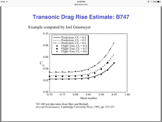
Aero Plots on the RASAero II Main Page will also show CD versus Mach Number. Mach 0.95 is when the big transonic drag rise begins. A little more Thrust, you get a little more Mach number, but then the CD rises. Small increases in thrust just increase the Mach number and increase the CD, and the rocket just reaches a slightly higher Mach number, until you can make it over the top of the CD "hump" at Mach 1.05. So Transonic you really want to punch through, and not linger there.


In the Flight Simulation, when you double click on the Motor Selection, on the right-hand side there are inputs for delaying the separation of the booster, and delaying the ignition of the upper stage. Dumping the booster immediately at booster burnout, but delaying ignition of the upper stage are common to increase altitude. Generally though I only recommend slowing down the sustainer to Mach 0.80, and not letting the coasting sustainer fall below Mach 0.80, before igniting the sustainer. If the coast Mach number gets too low, the sustainer weathercocks more and increases the downrange distance (the dispersion) of the sustainer, a big concern for two stage rockets for the Tripoli Class 3 (and over 50K ft) Committee.


On the RASAero web site there are extensive comparisons with altitude data here:

https://www.rasaero.com/comparisons-alt.htm


Good luck with your future flight!


Chuck Rogers
Rogers Aeroscience
 
I understand all of this. I've seen the curves. I understand that if you want to break Mach 1 you need to push through the transonic turbulence. I design my machbusters to sim to at least mach 1.2 to get past it all because if the sim suggests Mach 1.01-Mach 1.08, the likelihood is greater that in real conditions where heat and humidity are fluid, you won't break it. I really do get it.

HOWEVER... In this case I had a flawed file. I knew something had to be wrong with the file because the thrust-weight ratios and length of motor burn were too high for it not to sim past Mach 1. Rule of thumb among many I know who have broken Mach 1 often is about 12 G's of acceleration for 2 seconds is usually enough to get you through it. The rocket design was pulling over 20 G's during the booster stage and over 30 G's during the sustainer. Something was wrong with the math. My career involves doing a lot of math. I have learned to spot math errors even when I am not sure what the error is. YOu can tell when the numbers don't look right.

I reran the sim and came up with a set of numbers that I expected to see. The rocket in question actually sims to Mach 2.6... not Mach 0.99.

So at this point this entire discussion is moot and any further belaboring of the subject is unnecessary. I appreciate all the information. It is fascinating and I will go through it. But in this particular case, it was a math/software/user error that led to much lower than expected top speed...not aerodynamics and mach turbulence.

So can we PLEASE move on?

Sure, sorry I belabored the point.
 
Per the original issue RASAero II has a nice feature where you can plot Thrust and Drag, they are on the pull-down menu for Plots on the Flight Simulation. You can also plot Mach Number and Weight. In particular plotting Drag around Mach 1.0 will be very informative, especially when you look at Thrust at the same time period.

......

On the RASAero web site there are extensive comparisons with altitude data here:

https://www.rasaero.com/comparisons-alt.htm


Good luck with your future flight!


Chuck Rogers
Rogers Aeroscience

Thanks, Chuck. I like the program. I was a little intimidated by the owner's manual at first, but it is a good program. You do have to use a second program such as RockSim or OR to help you with your build and give you the weight and CG data you need to plug into RASAero. I was just frustrated when I saw two good sets of numbers and then one weird set.

I am admittedly not as well versed on Mach science, but I am very solid in math, and even though I don't know the cause or the solution right away, I can tell when numbers are bad numbers. Like I said earlier, it could have been how I entered the info or how I saved the file.

I absolutely agree with punching through mach instead of hanging around in transonic speeds for a second or two. In these two-stage designs, if the booster gets me above mach, I do not want the sustainer to coast back below it before it fires. No sense in going through that turbulence twice. Coasting an extra second or two below mach doesn't necessarily translate to much more altitude.

As much as the final flight will be an "extreme" flight, I don't really want to push the envelope as hard as possible. One set of motors could get me to 100K plus feet at a top speed of Mach 3.7. Another can get me there at a top speed of Mach 2.7. Since speed is not my goal, I'll opt for the slower approach and not have to deal with as much in the way of temperature extremes, and will be dealing with thinner atmosphere when I approach a transonic speed at a higher altitude. I've built a FG rocket that has hit Mach 2 using Tip-to-tip construction. As long as I stay below Mach 3, that construction should work just as well with CF.

There's a reason why the X-15 program didn't try to break Mach 5 3,000' above the Pacific Ocean and opted instead to do it 100,000'.
 
In these two-stage designs, if the booster gets me above mach, I do not want the sustainer to coast back below it before it fires. No sense in going through that turbulence twice. Coasting an extra second or two below mach doesn't necessarily translate to much more altitude.

In my flights, the booster speed is always above Mach 1, typically 1.5 or so. I always let it coast back below mach and then go through it again with the sustainer. One reason I'm using stabilization under the second stage is to allow the sustainer to slow down just a bit more (say, Mach 0.5 to 0.6 or so). One lesson I've learned over time with these flights is that the speed at staging and shortly thereafter is directly proportional to the dispersion radius of the wreckage....if you know what I mean. Once I figured this out, I started having more success and lost fewer rockets.

Jim

That's something I hadn't thought about.

I may need to rethink this. It would reduce the overall speed, and if I let it coast another 4 seconds instead of another 2, there will be a positive impact on altitude and overall top speed will be slower. If the top end comes down to Mach 2.4 or 2.5, I start getting into the realm where fiberglass could work instead of carbon fiber.
 
If the top end comes down to Mach 2.4 or 2.5, I start getting into the realm where fiberglass could work instead of carbon fiber.

The stress has little do with with your Mach number but everything to do with the drag force. If you design your sustainer so that it can support a compressive force equal to the thrust of your motor it will be strong enough because that will be the maximum stress the sustainer will see, regardless of mach number.

The structural failure, if any, will occur at your interstage coupler prior to staging.

--john

My understanding about FG vs. CF was that FG is more susceptible to the temperature extremes. Although at the end of the day, the epoxy used as the bonding agent is more important. The motor case will be the coupler at the forward end so if failure occurs there, it will be the FG that gives way.

I am waiting for the e-mail from Finsim to get the download info. I want to start working on Do... Does anyone know where I can find a fiberglass ogive 29mm nose cone?
 
Just to clarify high mach issues......

Drag is proportional to a Mach number dependent constant multiplied by the atmospheric density multiplied by the cross-sectional area of the rocket multiplied x the Mach number squared and divided by 2. https://spaceflightsystems.grc.nasa.gov/education/rocket/drageq.html

Aerodynamic heating is proportional to a Mach number related constant multiplied by the atmospheric density multiplied by the cross-sectional area of the rocket multiplied x the Mach number cubed.

The barrier that prevents you from going very fast in the lower atmosphere is not drag, it's heat. Eventually you rocket will soften and mechanically fail due to thermal effects. That's why the SR-71 was made from titanium and the MIG-25 was made from stainless steel. The airplane structure would have thermally failed if it were made from aluminum...... as will rocket nosecones and fins constructed from low temperature epoxy or plastics.
 
The barrier that prevents you from going very fast in the lower atmosphere is not drag, it's heat. Eventually you rocket will soften and mechanically fail due to thermal effects. That's why the SR-71 was made from titanium and the MIG-25 was made from stainless steel. The airplane structure would have thermally failed if it were made from aluminum...... as will rocket nosecones and fins constructed from low temperature epoxy or plastics.

Thanks, Bob.

That was my concern as well, and explains why nose cones used for Mach+ flights have aluminum tips. At one time I saw some formulae that could help calculate heat levels to help determine composites and materials that would do the better job. The reason why I liked the slower motor set alternative was that 1. At top speed the rocket was subject to less heat because it was a lower top speed... and 2. The rocket at top speed was subject to even less heat because it was achieved at a higher altitude where the atmosphere was much less dense and the friction was lighter.

Given that nose cone tips and fin leading edges are subject to the most heat, shreds are more likely to occur due to deformation from heat rather than turbulence. One thing I may do is paint it with automotive brake paint, which can withstand 2,000 degrees. Now all I have to do is find an epoxy that is just as impervious to heat.
 
Last edited:
Given that nose cone tips and fin leading edges are subject to the most heat, shreds are more likely to occur due to deformation from heat rather than turbulence. One thing I may do is paint it with automotive brake paint, which can withstand 2,000 degrees. Now all I have to do is find an epoxy that is just as impervious to heat.

The paint withstanding it is great, but if it conducts that heat as well it's of little use.
 
Aluminum looks cool, but it is actually a poor material for a high Mach nose tip for the reasons I stated. Paint won't do much either. Paint is thin and even if the paint survives at temperature, underlying low temperature material will be damaged. On a sustained high Mach airplane flight, aluminum will melt at Mach 3. Even stainless steel and titanium will melt at speeds above Mach 4. If you use the nose tip approach, graphite is the best material because it is lightweight and will radiate much of the heat away, but it will eventually oxidize.

What saves most high Mach hobby rocket flights is that while the surface can get hot, the underlying structure does not due to thermal conductivity and the short duration of the heating pulse. The ablative coating John mentioned has low thermal conductivity and will ablate when it gets hot, carrying away the heat as the surface evaporates. The pink X-15 used a similar silicone material. Phenolic epoxy is actually quite good with heat in a CF composite structure because it doesn't melt and flow, but ablates and dissipate heat. Either approach is much better than a metal surface in a rocket, and is a minimum weight solution.
 
The paint withstanding it is great, but if it conducts that heat as well it's of little use.

I would have to see, but part of me thinks it would need to have a high radiant ability. Otherwise it would act as an insulator and the brakes would get hotter, even though it is a thin layer. Good thought though and I would have to see some thermal conductivity data on it.

The rocket I build called "Houdini" was meant to push Mach 2. It flew great but unfortunately the transmitter puked right at liftoff and the rocket was never found. The fin construction on it was T-to-T FG and the epoxy blend included JB Weld at the leading edge, G-Flex on the rest of the fins, with RocketPoxy holding the fin to the airframe. My thought was that I would need a heat-resistant leading edge, a flexible trailing edge because I knew there was going to be fin flutter (had to slow it down so I would not punch the Potter waiver), and the shear strength of RocketPoxy. We know it reached apogee because we could see the event. after that it lived up to its namesake and disappeared.

From the photos Dave McCann took, it did not appear that there was too much spin. This was a frustrating day for me because it seemed like everything that could go wrong did except the up part of this flight. My video camera battery was dead, so I got out my cell phone, and its battery was near dead as well. The result was this 2-second video.

[YOUTUBE]q3i6syIPDVE&feature=youtu.be[/YOUTUBE]
 
Absolutely. The lowest drag produces the least aerodynamic heating. Sharp edges will get hot and disappear leaving a rounded surface. Considering the lowest drag configuration for a NC is the von Karman shape, it's the most likely form factor that an ablating forward facing surface will attempt to make, provide there is enough mass to allow it to form.
 
Back
Top