Need Help Getting This Motor Running(Solved)!

The Rocketry Forum

Help Support The Rocketry Forum:

This site may earn a commission from merchant affiliate links, including eBay, Amazon, and others.

TopRamen

SA-5
Joined
Aug 9, 2013
Messages
9,955
Reaction score
111
I took an electric fan motor from an old kerosene heater, and because it has four wires coming out of it, I am not sure how to safely wire it up, that I may use it to run the small scale foam lathe I'm assembling.
Each wire has continuity with the rest.
The model # is: Shinano Kenshi Co., LTD model IB-844-175

I did my googling and whatnot, and even went to the MFG. website, but was unable to find the information I need.
When the motor was in the now unusable heater, it ran at two speeds, and given the option, I would like to be able to use it like that on my foam lathe. This is only for the small scale version, so after I put the pulleys on it, it will not be under a heavy load at all.
I assume I cannot simply run my wall outlet into a dimmable lightswitch that is wired to the motor, but even if it is that simple, which wires are which? I am assuming the black is a Ground, but this is not familiar territory for me, as I'm used to using things like compressor motors that are already wired in an obvious manner and can hook right up to a three prong plug. It says that it is "Continuous Impedance Protected", but all that means is:

"A motor that relies solely upon the impedance of the windings to prevent overheating.

Tests for an impedance protected motor include winding resistance, input (no-load and locked rotor), 72 hour locked rotor temperature test, dielectric, 15 day locked rotor endurance test and dielectric. Three samples of each motor are required for testing.
"

Thanks in advance for any advice, and I don't "HAVE" to use this motor, but it ran the fan plenty good enough back when the heater was in use, so I know it does work, and it is right here in the box of pieces parts for tinkering with, so it is quite convenient if I can get it running.


Motor 2016-05-24 002.jpg
 
Last edited:
Normally white ground,grey or green neutral, black hot , blue hot also. Black and blue probably dont use at same time one is high speed the other low speed
 
Normally white ground,grey or green neutral, black hot , blue hot also. Black and blue probably dont use at same time one is high speed the other low speed

I would have to tend to agree with g zilla. No schematic on the old heater or inside the shell?
 
I have the metal parts/housing, but I tossed the wiring boards long ago, and just cut all the wires off to put into my miscelaneous wires box, so trying to trace what it used to be like can't happen. This pic' shows the circulation blower that I took the motor from, but it says nothing about what voltage is required, or which wire you give that voltage to.
How can I safely test it, and will I be able to perhaps use two switches, one for low and one for high, with a third to work as a safety to prevent both from operating at once?
There is a old fella that works at the hardware store that could probably show me how to use it, and I'll have to go there anyhow to get switches and wiring, so if that is what I should do as my best option, I'll do that rather than risk creating a hazardous situation.
The foam lathe will be an "Outdoor Use Only" item, but I don't want to do something stupid if I can avoid it by simply asking questions.

Heater Schematic 2016-05-24 001.jpg
 
Normally white ground,grey or green neutral, black hot , blue hot also. Black and blue probably dont use at same time one is high speed the other low speed

No, in the US green is ground and white is neutral. You should be able to verify ground by testing continuity between the chassis and the individual wires. The chassis should be grounded but high impedance to the other three wires. Hooking a hot wire to the chassis is a good way to get electrocuted.
You should be able to follow the wiring to and through the switch to see how it should be wired. You have a switch with three positions: off, low, and high, right? Use an ohmmeter to see what the switch does. I would suspect that the house hot wire comes into the switch. There should be two output wires from the switch. In the off position neither has continuity to the input wire. In low, one will have some measure of continuity. In high either the other output wire has continuity or they both do. Measure the resistance between input and output wires in all three positions. In the off position you'll see very high resistance in mega ohms, OL, or infinite, depending on you meter.
Depending on the motor type using a rheostat or dimmer could result in variable speed or running hot and possibly burning up.

Because the motor came from overseas don't strictly rely on the color of the wires (or advice from me for that matter).
 
Last edited:
No, in the US green is ground and white is neutral. You should be able to verify ground by testing continuity between the chassis and the individual wires. The chassis should be grounded but high impedance to the other three wires. Hooking a hot wire to the chassis is a good way to get electrocuted.
You should be able to follow the wiring to and through the switch to see how it should be wired. You have a switch with three positions: off, low, and high, right? Use an ohmmeter to see what the switch does. I would suspect that the house hot wire comes into the switch. There should be two output wires from the switch. In the off position neither has continuity to the input wire. In low, one will have some measure of continuity. In high either the other output wire has continuity or they both do. Measure the resistance between input and output wires in all three positions. In the off position you'll see very high resistance in mega ohms, OL, or infinite, depending on you meter.
Depending on the motor type using a rheostat or dimmer could result in variable speed or running hot and possibly burning up.


Thanks, but no, there is no switch, and that is the root of the problem.
It's just the motor with 4 wires coming out of it.
None of the wires get continuity with the housing of the motor.
They all have continuity with each other, so some form of rheostat or control was obviously in play somewhere, but I am not knowledgeable in these matters.

Motor With Wires 2016-05-24 001.jpg
 
Last edited:
Sorry my bad I knew that too. I had just woke up havent had my coffee yet
 
It's no big deal. I just thought that one of the folks here would be able to be like, "Here's what you do. You hook this to that and that to this."

I'll have to go to the hardware store anyhow, as I also don't have a pulley to fit that shaft, or a belt for that size pulley for that matter.
 
They all have continuity with each other through their windings, but you should be able to measure different levels of impedance. I'll see what I can find that might help.

Thank you, and don't be afraid to tell me I'm out of luck, and should have thought of this before I disassembled the heating unit.:)
 
Shinano Kenshi designs motors for specific applications so they don't publish tech bulletins. What brand and model of heater was it?


[emoji1010] Steve Shannon [emoji1010]

It was a Monitor model 41.

I did'nt think to maybe look for info on the heater.
It came with the house but there was no owners manual.
When it broke, it was the insides of the burner pot, and it could not be rebuilt, so I needed a whole new heater.

Thanks for your help.
 
Last edited:
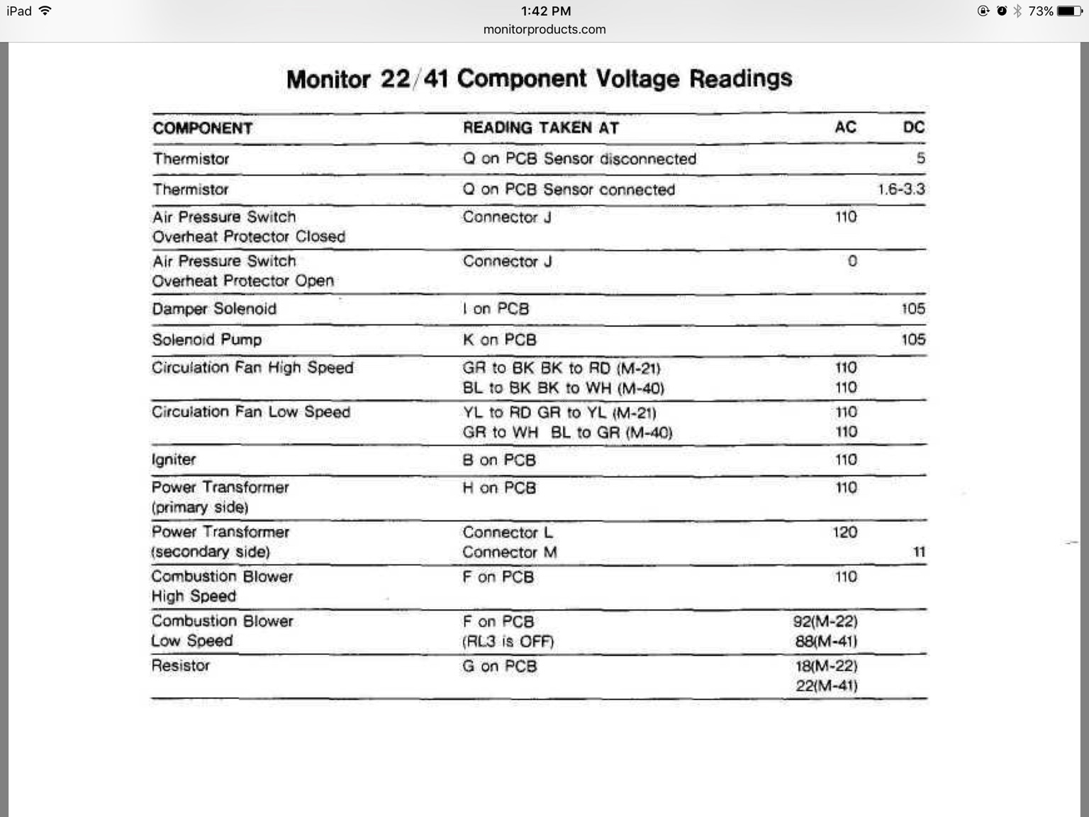
Okay, the voltages I referred to earlier are for the combustion blower, not the circulation blower. Here's the page that helps the most:
3ed1315b7b73e5d55d4b394d9a5116b9.jpg

For running at hi speed, you connect 110 vac to blue and black and white and black. For running at low speed you connect 110 vac to blue and gray and white and gray, I think, based on the lines in the center of the table I've attached. Unfortunately, the part of the schematic that I think we really need is cut off on the bottom of page 61 of 69.


[emoji1010] Steve Shannon [emoji1010]


Awesome, so I can use 110, and only need switches, the speed control is built into the motor.

I can set up two switch boxes, as you describe, with the wires spliced together between the two I think.

I suppose in theory, if I have the wrong wire as the ground wire, either nothing will happen, the motor will run in reverse, or there will be sparks and good times!

Maybe I need to take a step back and do a little more research, but knowing that the motor can have straight 110 current like if I was just wiring up a light switch.

I'll draw up what I think will be a working diagram of it's wiring, then make a test box to put it in to try it out.

I'll go see if youtube has any random info that may help too.


Thank you for digging that info up for me!
 
Youtube has some videos. :)

[video=youtube;oyppEsC7n5s]https://www.youtube.com/watch?v=oyppEsC7n5s[/video]
 
Go with the You Tube video!!!!! Connecting 110 vac to blue and black and white and black makes no sense. The service manual is giving you the voltage measured between the different colored wires in the high and low speeds not how they are connected.

Steve G
 
Go with the You Tube video!!!!! Connecting 110 vac to blue and black and white and black makes no sense. The service manual is giving you the voltage measured between the different colored wires in the high and low speeds not how they are connected.

Steve G

I'll gather some wires and switches and play with it tomorrow.

I'll plug it into my foot button I use for running my rotary tool, as it has a momentary contact switch so I can tap it quickly to see what happens with each configuration.
 
Last edited:
If I'm wrong, and without that part of the schematic I'm not convinced either way, this could let the smoke out. I found a service manual for a model 441, which is the replacement for the 41, but the quality of the scanned schematic is much worse.
The colors are meaningless except to differentiate the wires. Those voltages would be correct if the relay outputs connect to the motor on those wires. Please do be careful. I would connect it to a power strip with a circuit breaker. Then, once everything is wired up just turn on the power strip and see if it works.
Although I've been an engineer for 25 years, 20 years as a PE, I can't tell you for sure that I'm right, but the wiring I described is what I would try, very carefully. It would sure be nice to have the rest of the schematic or the control board.
 
I called Mr. B at the hardware store, and he said to bring it in and he'd have a look, so I did and he tried to get it going and said it must be shorted out, so he gave me a discarded motor from a dehumidifier with a speed control/switches and whatnot that works fine.
In the Agro Bin isle I got some parts to make the armature accept a vacuum cleaner flat belt, and some bearings for both 3/8" and 1/2" steel rods which I also got while I was there, along with some other miscellaneous hardware that I might need, so now I can start designing my foam lathe.
I have an account there and still get my employee discount from when I ran the sporting goods dept., so I was able to get everything I might need for under $40, and he just gave me the motor.:)


New Motor 2016-05-25 002.jpgNew Motor 2016-05-25 001.jpg
 
Back
Top