Saturn 1B - 1/23 Upscale

The Rocketry Forum

Help Support The Rocketry Forum:

This site may earn a commission from merchant affiliate links, including eBay, Amazon, and others.

MaxQ

Tripoli 2747
Joined
Jan 18, 2009
Messages
4,508
Reaction score
130
Location
Central Viginia - USA
I've taken a look at the various Saturn 1B kits available from 1/70 to 1/48th and thought it would be pretty cool to make a larger version.
I'd be continuing the lightweight materials build concept I did with previous projects, with the idea of keeping motor selection in the range of something long burn low peak thrust to help hold the thing together.
The 8.5 inch Apollo Little Joe II that I built at 1/18th scale was made of lightweight materials, all poster board, foam core, balsa and came in around 3 lbs, dry. Has flown nine times and the roughest part has always been the landing.

burkefj / Frank has done some excellent work with larger lightweight scale projects like his foam Pershing Missile.

https://www.rocketryforum.com/showt...rge-Pershing-1A/page2&highlight=pershing+foam "Lightweight Large Pershing 1A"

The theory, as I see it, is how big can you go? - if you go high power, but keep the motor impulse within reason thereby avoid the need for a heavily reinforced structure thus keeping a lighter overall weight - all within reasonable limits.

Cluster air starts in some of the eight tank tubes? - yes, that would be nice.

For clusters, I like a central core motor that is the highest impulse of the motors and ignites first, gets the thing moving and straight in flight.
Don't like unsymmetrical thrust. I may even cant the outboards like the popular Deuces or Tress.

First step (as previously posted in "Scale" ) was doing a number of calculations to see how big this thing would get using readily available components for the main section, which is the eight tank tubes in the fin can of the airfame.

Options for the eight tank tubes in this larger upscale of popular kit versions were standard 2.6 inch diameter body tubes, 3 inch diameter tubes, or the 4 inch diameter, all from Loc P.
These would also predict how big the most difficult to fabricate part would get, which is the main airframe section forward of the tank tubes - that part will enclose the eight tubes aft in the fin can.
That component got very big quickly on paper - using the 4 inch tubes.
3 inch diameter Loc P. tubes get expensive when you need eight of them, and they are only 34 inches long...four inches shorter than required.

I found some very lightweight Scotch brand 3 inch diameter mailing tubes locally - at the fraction of the cost of other options.
They were very light weight as they are thin wall, which is a definite plus in the aft end of this thing...hopefully less nose weight.
Standard 3' Loc P. couplers also fit nicely in my samples, which is good, since these tubes are 36 inches long - but will still require 2 inch extensions.

Drew up a template which shows the main airframe would come in at 11.2 inch diameter.
Airframe Cross Section.jpg


Dimensioned Tank Tubes.jpg
 
Last edited:
A search for something to serve as either a main body tube or a mandrel (to roll my own) had various sonotbe tubes at 10 inch to 12 inch.
Not exactly in scale.

I did find one that looks close enough.
Roughly 11.5 inch diameter.
Very heavy...and rough.


If I roll a light weight fiberglass tube around that - which I could cut longitudinally to adjust the diameter, that might work.

Upscale Saturn 1B - 3in. Tank tubes.jpg
 
Last edited:
With 3 inch diameter tank tubes aft, (and 11.5 inch airframe forward of that) all setting the size and scale overall, dimensioning the rest of it came next.

I sketched up the comparable size of the service module, the Apollo capsule, and the escape tower, in order to determine what parts would be required at an overall 1/23rd scale.

Escape tower comes in at 1.12 inch diameter, - very feasible for that part.
A standard 1 inch diameter body tube is close enough for me.

Service module diameter comes in at 6.68 inch diameter, by 7.66 inches long.
Not so good.
Have to think on that one.
Guess I could roll something that short to that exact non-standard diameter.
Now I have to consider how this all goes together internally.

Other projects have used a central core motor mount as the main load bearing structure which the recovery system attaches directly to, as well as the fins - in a "thru the wall" fashion to take landing strikes.
The rest of it kind of goes along for the ride.

Cluster outboards will require a good support system internally, but they would be motors more for effect.

Scale Dimension Service Module - Escape Tower.jpg
 
Last edited:
George has some wonderful scale drawings that make this job so much easier.
Thanks for your work George.


Looking at the internal structure of this thing, some reinforcement of the airframe skin will be required in several places for the rail button attachment points, then through to the central core.
Will need to support the weight while on a rail.

The larger fin can ring at the bottom end that juts out further than the mid section airframe will make this an interesting design problem.

Any ideas on how to line up and attach rail buttons?
The forward rail button will need to stick out further to be in alignment with the lower rail button on the fin ring.
I guess a standoff of some sort would do the job.

View attachment 290977
 
Last edited:
So I've drawn up a template for the two or three tube tank spacers that will mount onto the core motor mount and align and hold the eight tank tubes.
Broke out the protractor to do some tighter dimensioning of the internal geometry here.
Eight fins around the full 360 degrees at the 45 degree mark each.

Centered each tube at the 22.5 degree mark in each 45 degree section - adjusted the location of the tube outward to allow for the 1/8 inch fin bracket thickness between each tube.
Fin brackets would extend to the central core and seat on the central core motor mount, with some buttressing of some sort.

Tube spacer template highlighted in yellow.

This is a rather complex shaped thing - it would be impossible for me to cut out of plywood, given I don't have a full workshop.
I'll bet this would be a challenge for anyone to cut out of plywood, except for maybe those CAD/CAM outfits that laser cut giant 1/4 scale RC airplane parts.

I'll be cutting it the easy way - out of foam core.
Hence, given the nature of the material used - it won't be a load bearing part, just something to hold the eight tubes in correct alignment until I attach the actual load bearing tube supports between the inside of the tubes and the center core.

Tank Tube Spacer.jpg
 
Last edited:
DANG!! this is going to be awesome!


A search for something to serve as either a main body tube or a mandrel (to roll my own) had various sonotbe tubes at 10 inch to 12 inch.
Not exactly in scale.

I did find one that looks close enough.
Roughly 11.5 inch diameter.
Very heavy...and rough.


If I roll a light weight fiberglass tube around that - which I could cut longitudinally to adjust the diameter, that might work.
 
DANG!! this is going to be awesome!

I'll try my best...

Anyone have any advice on carbon fiber cloth for the airframe or fin ring...?
I've got a vacumn bagging outfit that I intended to use for RC sailplane wings - but never used, and I'm not sure I want to try and bag a 11.5 inch diameter tube.

I like the idea of strong lightweight fabrics to keep this beast within reasonable weight limits.
My experience in glassing is limited to wet lay up over birch plywood for sailplane fueslages and my level 2 project (Binder Raptor) with a couple of weights of FG on the airframe, nothing exotic.
And small parts like nose cones and nozzles on scale projects.

I'd like to get a selection of cloths that would make a reasonable lightweight airframe.
 
Last edited:
Today - cut out the spacers that will mount on the central core motor mount for alignment of the eight tank tubes.
After trimming and test fitting, I'll reinforce them. Then mount them on a much longer central core tube.

These are solely for alignment - the weight will be carried by birch ply mounts on each tube along the central core.

Intertank tube spacer1.jpg Intertank tube space r2.jpg
 
Last edited:
I've been going over price lists of CF fabric at CST and Aerospace Composites.
Lots of choices out there.


CST/The Composites Store : there are reasonable price rates available in 42 "wide rolls in 2.0 to 3.5 oz. and 5.7 oz. for minimum quantities (lengths).
LIGHT WEIGHT CARBON FIBER FABRIC, 3.5 oz./sq. yd., 42" wide 3.5 oz. Carbon Fiber Fabric - Plain Weave
24 X 24 Thread Count 0.007" Thick

https://www.cstsales.com/carbon_fabric.html

- Carbon Fiber 5.7oz 2x2 twill seems to be popular in other build threads.

Aerospace Composites: Prices look higher here for lower quantities of comparable CF cloth, although the hybrid aramid/CF cloth looks interesting and less expensive:

https://www.acpsales.com/Carbon-Fiber-Woven-Fabrics.html
https://www.acpsales.com/Carbon-Aramid-Fabric.html

5.4 oz Carbon/Aramid Yellow Fabric: 50" Wide 2x2 Twill
"This Carbon Fiber/Aramid hybrid offers the stiffness of carbon fiber and the impact resistance of Aramid all in one material. It is manufactured with 3K Carbon and KEVLAR® fibers and the 2x2 twill weave allow for easy layup on compound curves.
The Aramid fibers are dyed with red, blue or yellow dyes for eye-catching color."


CarbonKevlar-Yellow-01.jpg
 
Last edited:
I prepared a poster board capsule shroud for test fitting on two different body tube mandrels.
Calculations indicate the capsule base diameter should be 6.68 inches.

My search for body tube material for the service module body tube only turned up a 6.25 PVC tube from the hardware store, and 7 inch diameter tube that I think may have been a Loc tube from way back when.
The 6.25 inch PVC tube is .43 inches too narrow for the capsule, the 7" Loc tube is .32 too wide.
Pictures show the degree of error in matching the calculated capsule diameter.

First problem to resolve, I may just have to hope the size discrepancy from either choice of tubes (too narrow or too wide) isn't very noticeable on the final model, or keep looking for a 6.68 inch tube.

Second problem....either way; the undersized fit of the capsule on the 7 inch tube, or the noticeable overshoot on the sides of the 6.25 inch tube will have to be dealt with.

I think if I heavy up on the fiberglass wraps on the 6.25 inch PVC tube I can reduce the apparent overlap some.
But that is an extra 1/4 inch per side. That's a LOT of wrapping.

The 7 tube might be a better choice for rolling a tube....if I can widen the capsule shroud a total of .32 inches....

Apollo Capsule Shroud on 6.25 in..jpg Apollo Capsule shroud on 7.0 In..jpg
 
Last edited:
Made the main airframe shroud and did a test fit on the central core tube that will extend through the airframe - then for laughs, hung a scale drawing of the service module capsule for comparison.
Central core tube may be smaller diameter, but the recovery parachute as packed up will probably need to dictate that minimum diameter.

Shrouds will be fiber glassed and internally braced with triangular reinforcement - longitudinally.

Airframe Shroud.jpg Shroud with Service Module capsule mock up.jpg
 
Last edited:
Man, and I thought my dream 1/48th or 1/45th scale Saturn V would be a big build...

You know I'll be watching this... :pop:
 
I prepared a poster board capsule shroud for test fitting on two different body tube mandrels.
Calculations indicate the capsule base diameter should be 6.68 inches.

My search for body tube material for the service module body tube only turned up a 6.25 PVC tube from the hardware store, and 7 inch diameter tube that I think may have been a Loc tube from way back when.
The 6.25 inch PVC tube is .43 inches too narrow for the capsule, the 7" Loc tube is .32 too wide.
Pictures show the degree of error in matching the calculated capsule diameter.

First problem to resolve, I may just have to hope the size discrepancy from either choice of tubes (too narrow or too wide) isn't very noticeable on the final model, or keep looking for a 6.68 inch tube.

Second problem....either way; the undersized fit of the capsule on the 7 inch tube, or the noticeable overshoot on the sides of the 6.25 inch tube will have to be dealt with.

I think if I heavy up on the fiberglass wraps on the 6.25 inch PVC tube I can reduce the apparent overlap some.
But that is an extra 1/4 inch per side. That's a LOT of wrapping.

The 7 tube might be a better choice for rolling a tube....if I can widen the capsule shroud a total of .32 inches....

View attachment 291604 View attachment 291605

Use a layer of balsa around the tube to bulk up to the shroud instead of wraps of glass, then put a single layer of glass over the balsa to bring it all together nice and strong.
 
Use a layer of balsa around the tube to bulk up to the shroud instead of wraps of glass, then put a single layer of glass over the balsa to bring it all together nice and strong.

Now there's a thought. I've wetted out and wrapped thin balsa sheet before.
For thicker sheeting , I could lay down some balsa strips and sand them round.

BTW: Rich has a pretty nice L3 build thread for his Cherokee with some FG and CF layup for those interested.
I'll be taking another look at his work before I get into doing fins.

https://www.rocketryforum.com/showt...okee-D-L3-build-thread-for-rharshberger/page6
 
Last edited:
I have two rolls of CF cloth on order...it was conveniently available in 50 " wide rolls which will allow me to take down that upper 36 inch long airframe area in less than one length of the roll.
Left overs - I think I might like to use them to vacuum bag some CF fins.

I made a 3X enlargement of the stock kit fins.
Seven inches long on the fin TE.
My fin template is giving me a bit of a concern.
I think the kit fins might have been enlarged with the kit, but I think the fins need to be bigger still.

I plan on keeping the weight of this build as far forward as possible to avoid lots of nose weight, which tends to happen sometimes with scale projects.
I hope the eight fins on this project helps.

3X upscale fin.jpg
 
Last edited:
While I wait for CF fabric to arrive for the airframe and fins, and a body tube order for the core motor mount assembly, I'll turn my attention to other components.
Went shopping this afternoon for materials for the escape tower.
This part was one of the most labor intensive on the 1/18th scale Apollo Little Joe and required a jig to assemble it.
I oversized the vertical tower parts as I couldn't find anything exact...but in hindsight it worked out fine, that tower has never broken in any of the launces or landings, not one dent or crack

I thought about going with brass rod but I can't stand the thought of soldering all those joints.
Wood dowels if they scale just right are easy to work with and assemble.

My calculations indicate the tower vertical structure at 3/16 inch diameter and horizontal truss members at 1/8 inch diameter.
Perfect.
Two separate trips to the local Hobby Town turned up some 1/8 inch wood dowels - lots of them.
No dice on the 3/16th.
An impulsive stop by an AC Moore turned up all the 3/16th inch dowels I'd need.
This build may be a bit of deja vu , just smaller.
This is a shot from the oversized 1/18 scale build.
Looked better when painted.

LBJ%20II%20-%20Tower%20detail%202.jpg
Painted:
View attachment Apollo LJ-II ApolloCapsule.JPG
 
Last edited:
Assembled a jig from 1/8 ply to build the launch escape tower.

A friction fit holds the tower structure in place inside the jig while building the tower.

Keeping the jig aligned while pulling the assembly out of the jig requires the holes in the jig let go of the assembly easily.
Last thing you want to see is the trusses start pulling apart while pulling the tower assembly out of the jig.

Tower jig 2.jpg Tower jig 1.jpg
 
that tower looks amazing!!!


While I wait for CF fabric to arrive for the airframe and fins, and a body tube order for the core motor mount assembly, I'll turn my attention to other components.
Went shopping this afternoon for materials for the escape tower.
This part was one of the most labor intensive on the 1/18th scale Apollo Little Joe and required a jig to assemble it.
I oversized the vertical tower parts as I couldn't find anything exact...but in hindsight it worked out fine, that tower has never broken in any of the launces or landings, not one dent or crack

I thought about going with brass rod but I can't stand the thought of soldering all those joints.
Wood dowels if they scale just right are easy to work with and assemble.

My calculations indicate the tower vertical structure at 3/16 inch diameter and horizontal truss members at 1/8 inch diameter.
Perfect.
Two separate trips to the local Hobby Town turned up some 1/8 inch wood dowels - lots of them.
No dice on the 3/16th.
An impulsive stop by an AC Moore turned up all the 3/16th inch dowels I'd need.
This build may be a bit of deja vu , just smaller.
This is a shot from the oversized 1/18 scale build.
Looked better when painted.

View attachment 291696
Painted:
View attachment 291701
 
I thought this video might give you another view of Apollo 7's launch...kinda a different launch angle with some neat views. For what its worth, I think your fins may look better than the original! Nothing like watching a Saturn launch for inspiration during a build as I always say....
[video=youtube;cNwxG8FbEiM]https://www.youtube.com/watch?v=cNwxG8FbEiM"]https://www.youtube.com/watch?v=cNwxG8FbEiM[/video]

Excellent vid, thanks for posting.
Haven't seen that one. 01:12 into the video...nice shot of the aft end and fins.
I'd love to get a couple of those outboards canted to get an angle like in this vid.
A central White Lightning with outboard Metalstorms maybe....?

The fins...I have an older version of RockSim which I have yet to transfer to my new computer and update.
I'd like to see if enlarging the fin size would be preferable to adding nose weight to get the CG/CP where it needs to be.

Unnecessary weight is something I'd like to avoid on this project.

Like to verify speed on the rail as well.
 
Last edited:
I cut out the profile of the Saturn 1B airframe from George's plans to do a cut and paste up of a rudimentary schematic to illustrate how the airframe might separate into sections for a dual deployment scenario.
These crude paste ups are easier to convey the concepts than trying to describe them.
Schematic only - the lengths of bridle are not to scale.

I'm trying to decide if there is a down side to one or the other.
Some things to consider here ..................and I could use some advice from you guys.

First problem to resolve: should the service module / capsule remain attached to the main airframe as shown in both scenarios here?
Or should it recover completely separately?

I considered having the service module / capsule completely detach and recover separately.
Then I thought perhaps being smaller it would be up there by itself, it might even be up there much longer, with a much greater hang time, more susceptible to wind drift etc. - unless there is a lot of weight in it.

Then again, keeping the service module / capsule bridled to the main airframe as shown in option A. or B. - might subject it to a lot of banging around on the main airframe and knock the escape tower loose.
I think the escape tower could be made much less susceptible to damage if the service module / capsule recovered separately with it own smaller parachute - in a horizontal mode by tethering it with a bridle to the escape tower.

I'm also wary of which part of the airframe the large shroud/transition is attached to - to the main central airframe (as in A.) - or to the service module /capsule (as in B.) ?

This component is thinner walled and will be somewhat fragile even after it is fiber glassed.
I think the larger diameter of the shroud transition will be more susceptible to damage and crimping if exposed (as in scenario B.) than if only he narrow diameter part is exposed (as in scenario A.).

Then again, in scenario A. the opening for the main parachute to eject is much smaller than the opening in scenario B.

A. Dual Deploy seperation A.jpg B. Dual Deploy Seperation B.jpg
 
Last edited:
After considering the benefit of completely detaching the service module / capsule, and having it recover under a smaller parachute suspended at an angle - here is scenario C.


C. Dual deploy seperation C..jpg
 
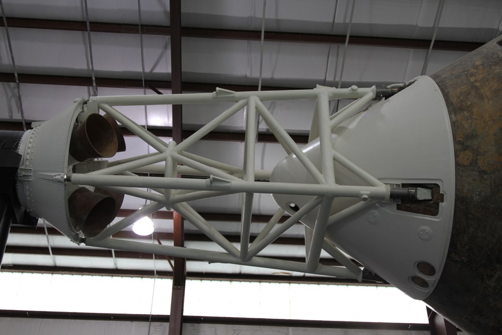
First batch of upper and lower escape tower V struts have been cut out from 1/8 inch wood dowel and assembled.
The angled cuts on each end are time consuming.......
They will be dropped into the inside of the tower and hold the structural ring.

Escape Tower Upper and Lower V struts.jpg Apollo Escape Tower -Heroicrelics.jpg

Mike Lachance picture
8617281829_feba7745e8_b.jpg


Diagram from Heroicrelics/org[/IMG]
https://heroicrelics.org/info/csm/les/les-exploded-diagram.jpg
 

Attachments

  • Apollo LES tower A.jpg
    Apollo LES tower A.jpg
    151.9 KB · Views: 133
Last edited:
First two sets of exterior truss work installed.
Test fit, sand ends of dowel to adjust, refit, tack glue with superglue, epoxy joints to follow.
So far I've only managed to glue my fingers to the tower once, so it's moving right along.

LES truss work.jpg
 
Cut the Jig and pulled the tower, applied the last exterior truss work.
Will need to look for a structural ring the same scale before the interior V struts get installed.

The BT for the escape rocket is a standard 1.12 inch diameter.

The LES nozzles were enlarged from the kit shrouds and will be made of mylar and fiberglassed.

Tower and LES nozzles.jpg
 
Use a layer of balsa around the tube to bulk up to the shroud instead of wraps of glass, then put a single layer of glass over the balsa to bring it all together nice and strong.

You could get some 1/8" thick nonexistent honeycomb core material. Laminate a layer around the tube, then a layer of two of glass or carbon and you are there.
 
Back
Top