Fliskits Spitfire - Beer Can Version - Build Thread - FINISHED

The Rocketry Forum

Help Support The Rocketry Forum:

This site may earn a commission from merchant affiliate links, including eBay, Amazon, and others.
I decided to finally deviate slightly from the plans. The printed tail cone is 110# card stock, but it could be a little more sturdy since there will be fins glued to it. I could have coated the inside with epoxy but since I happen to have a spare cone sitting right there...
View attachment 288236

... I thought I remembered something HCMBanjo wrote up somewhere about a super cone, or something like that, where two cones were glued together to make one that's more structurally sound. I made sure the seams were 180 degrees apart. Maybe HCMBanjo will see this and give more details about what I'm thinking of.
View attachment 288237

Hi Mustang -
That article was posted in the Apogee Peak Of Flight newsletter in 2013:
https://www.apogeerockets.com/education/downloads/Newsletter349.pdf

The double layer shroud should work fine on the tail end of the Acme Spitfire.
Even though it adds a little weight, altitude is not really a concern with the Spitfire.
I have built the Macme Shrew (MMX Spitfire)
https://modelrocketbuilding.blogspot.com/search/label/FK MACME

The "Super Shroud" idea came about to strengthen nozzle style shrouds around the exposed nozzle end.
One hard landing and a single layer shroud (touching down first) would easily crimp up.
I have also used the double layer shroud on card stock adapters with good results.
I'm looking forward to the rest of your build! The beer can idea is great.
 
Ummm. . . Beer! Silver Bullets or Banquet. Pure Rocky Mountain spring water. Wish I could take the brewery tour every day.

That rocket looks mighty crooked and it is made out of old beer cans! Here, hold my beer and let's see if it flies:)
 
Now that the glue along the bottom CR and the tail cone has dried I can cut off the overhang. I started to try this with an Xacto knife but found scissors was a lot easier.
048 Cutting overhang.jpg

The scissors didn't do a perfect job and there were a couple of places where the printed wrap tore slightly, but dabbing a little glue and pressing the print back in place seemed to fix it right up.

Now the wrap is flush with the bottom of the centering ring.
049 overhang off.jpg
 
Section 2, which I'd previously glued to centering ring 3, was now able to be test fit in place.
050 Test fit Section 2.jpg

Section 2 fits over centering ring 2, which is on the top of the tail cone but sticking halfway out. This section slides on 180 degrees from how it was cut off of section 1. The red line on section 2 lines up with the black line on section 1. Of course section 1 is now covered by the tail cone but fin location 1 is lined up with the black line so that's what I used.
051 Section 2 on CR.jpg

Here's a picture of the test fit from above the tube.
052 Section 2 from above.jpg

And from the side. You can see how the wonky angles are starting to really make this look screwy.
053 Section 2 in place.jpg

Before removing Section 2 I drew a pencil line around the motor tube so I'd know where to add some glue. That way when I slid it back in place the centering ring would be glued from below.
054 Section 2 marked and removed.jpg
 
Glue was added to the pencil line, and to the top of the tail cone, and then section 2 was slid into place. I was careful to make sure it was placed with the proper alignment of red and black lines. Notice the tiny hole near the center of the black centering ring?
055 Section 2 glued.jpg

All of the centering rings have tiny holes in them and are used to check proper alignment. Here's a launch rod slid through 3 of them. It's correct so far. Hooray!
056 Section 2 alignment checked.jpg
 
It should be a prerequisite that any build thread of the Spitfire, or the MACME Shrew have the original inspiration of the rocket in it in the original post.

074d7047de5869c4a7e9f6f0c7f855c3.jpg
 
While the glue dried I decided to test fit section 3. It will fit like a glove.
057 Section 03 test fit.jpg

Section 3 was removed and centering ring 4 was test fit to the top. It was loose enough that it couldn't be put into place snugly, so I added a little glue to the inside of the tube and put the CR in place. As the glue set up I was able to keep moving the CR slightly so that it would be halfway out. [Edit: read the warning at the bottom of this post before gluing this CR!!]
058 Section 3 with CR 4 glued halfway.jpg

I have no idea how this could have been done if the tube was already glued to the rocket, per the instructions, so I'm glad I finally decided not to follow the instructions to the letter. As soon as the small amount of glue sets up enough I'll add a fillet of glue to the CR along the inside of the tube.
059 CR 4 barely glued.jpg

Edit: WARNING!! This CR, number 4, is the first one where the alignment notch lines up with the RED line. If you glue it in the wrong orientation as I've just done, you'll have the problems I have in the next bunch of posts. Don't do this. Save yourself. Read the instructions. Never deviate from them.
 
Last edited:
While the glue dried I decided to test fit section 3. It will fit like a glove.


Section 3 was removed and centering ring 4 was test fit to the top. It was loose enough that it couldn't be put into place snugly, so I added a little glue to the inside of the tube and put the CR in place. As the glue set up I was able to keep moving the CR slightly so that it would be halfway out.


I have no idea how this could have been done if the tube was already glued to the rocket, per the instructions, so I'm glad I finally decided not to follow the instructions to the letter. As soon as the small amount of glue sets up enough I'll add a fillet of glue to the CR along the inside of the tube.

Seems to me, that small paper tabs could be glued to the inside of the body tube that the CR would then be nested between. If the tabs were long enough, perhaps using gussets glued to the CR to reinforce them, you could make the build a little easier (for adding the next section).

 
Mushtang, this is REALLY looking good. You do very nice work! I'm on pins and needles waiting to find out if those wraps work on the rest of the rocket. BTW. Almost got all of the MACME Shrew configured as a Template. Once done I can slight minature beer labels in that one if you are so inclined! :)


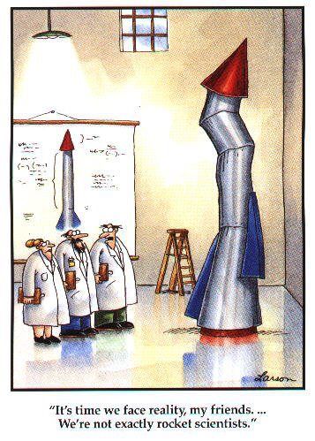
K'TESH - Love the FarSide rocket!
 
Seems to me, that small paper tabs could be glued to the inside of the body tube that the CR would then be nested between. If the tabs were long enough, perhaps using gussets glued to the CR to reinforce them, you could make the build a little easier (for adding the next section).

54b3e46b_not-sure-if-serious.jpeg
 
Mushtang, this is REALLY looking good. You do very nice work! I'm on pins and needles waiting to find out if those wraps work on the rest of the rocket.
I'm sure they'll look great, thanks to your fine work. If not I'll burn you with cigarette butts.

BTW. Almost got all of the MACME Shrew configured as a Template. Once done I can slight minature beer labels in that one if you are so inclined! :)
I actually tried building the MACME about a month ago and I messed up somewhere along the way. The nose cone didn't fit right and I wasn't satisfied with it. My wife's favorite rocket in my collection is the Spitfire so she really wanted the MACME to set on her desk.
 

Serious...

You glue the tabs to the inside of the segment, slide the CR down so that the tabs are sandwiched between the CR and the segment (thus tightening the fit).

Another idea would be to glue tabs to the CR's underside, then use them to pull the CR up if it gets recessed too far down. After the glue dries, trim them off.

Yet another idea would be to glue a strip of paper inside the segment to act as a shelf to prevent the CR from falling too far down.

Oh, couldn't tell. Well it seemed like putting a little glue on the CR and moving it with my fingers until it stayed in the right position, and doing that before gluing that segment onto the rocket was easy enough. So that's what I did.
 
I sure hope so. I'll try to show a lot of pictures and document any mistakes if/when I make them. I usually goof up at least a couple of times per rocket build.
Well #&)@$#%!!!!!

I don't know what happened. I really don't. Maybe someone that's built one of these can tell me. Oh wait, I'VE built one and I still don't know. This morning I went to get section 3 and slide it into place to test fit it and it didn't fit.

Luckily I had the cutting guides still on the table so I could slide them onto the sections and see where I cut wrong... but they all fit and it looks like I've cut the tubes where I should have.

Here's the Section 2 guide on the tube, and the guide is flush all around. The motor tube is in the CR and it all lines up with the stuff below, so it seems like it is on correctly.
061 Section 2 with cutting guide.jpg

Here's the other side. Still flush.
062 Section 2 with cutting guide.jpg

Here's the bottom of Section 3, the guide and tube are flush.
063 Section 3 with cutting guide.jpg

And from the other side.
064 Section 3 with cutting guide.jpg

And yet, when I slide section 3 onto the motor tube the bottom is not flush with the section 2 tube.
065 Test fits badly.jpg

This rather large gap is in place and no matter how I turn the tube it won't close up.
066 big gap.jpg

I don't understand this. I followed all the instructions TO THE LETTER!

Well, maybe not. My guess is that gluing the CRs in before installing the tubes might be the issue, although this is exactly how I did it the first time I built a Spitfire and it worked that time. I'm not sure what to do.

Perhaps cut a piece of card stock to try and fill in the gap? But with no CR on the bottom of Section 3 it's not going to be very structurally sound. This just sucks.

:facepalm:
 
Looking over the design, I would guess that you may have used an incorrect ring someplace, or you may have glued one in the wrong orientation.

If you could do 3 more pix, it may help.
1) a pic of those two sections together, but from 90 degrees around (so I can see the solid and dotted align,net lines)
2) the top of section 2 showing the centering ring as well as the alignment notch and alignment line
3) the top of section 3 showing the same.

Additionally, re-review steps 16-20, as I am doing. We should be able to figure this out :)

And, no worries, whatever it is, it can be fixed.

Jim
 
you may have glued one in the wrong orientation.

3) the top of section 3 showing the same.

THAT'S IT!!!

I read over the steps what felt like a dozen times, but I didn't do it right. CR 4 has the alignment notch aligned with the BLACK line instead of the RED line.

Thanks for showing me where to look!!

Here's Section 3 rotated 180 degrees on the motor tube.
067 Section 3 rotated around.jpg

The top of Section 2, with CR 3 aligned correctly with the BLACK line.
068 Section 2 and CR 3 correct.jpg

The top of Section 3, with CR 4 aligned incorrectly with the BLACK line. I should be on the RED line. Dang it.
069 Section 3 and incorrectly aligned CR 4.jpg

So I'll try and remove the CR but I doubt I can do it without destroying the tube. I'll just be happy if I can remove the CR without destroying the CR. If I can I'll head to the hobby shop and buy another tube to cut.

Thanks for the direction on where to look Jim! If you see anything else in the pictures that I did wrong feel free to point those out as well.
 
There was enough glue on there to keep me from being able to cut the CR out of the tube without damaging either. To keep from damaging the CR I went ahead and used scissors to cut the top inch off the tube.

070 Section 3 cut.jpg

Then I was able to pull the rest of the tube off the CR and away from the glue.
071 CR 4 ripped off.jpg

Using some sandpaper and knife I believe I've removed enough glue and tube to be able to reuse the CR.
072 CR 4 cleaned up.jpg

Unfortunately I don't have any BT-70 here at the house to cut another section from. So I drove to Hobby Town USA, Michael's, and Hobby Lobby, and none of them had any either.

Maybe I'll get lucky and find something on Amazon Prime that might be here soon.
 
Mushtang...you have Jim Flis on your Tiger team working the problem!!


Looking over the design, I would guess that you may have used an incorrect ring someplace, or you may have glued one in the wrong orientation.

If you could do 3 more pix, it may help.
1) a pic of those two sections together, but from 90 degrees around (so I can see the solid and dotted align,net lines)
2) the top of section 2 showing the centering ring as well as the alignment notch and alignment line
3) the top of section 3 showing the same.

Additionally, re-review steps 16-20, as I am doing. We should be able to figure this out :)

And, no worries, whatever it is, it can be fixed.

Jim
 
Daddy...I saw a T shirt today that said BEER....is proof that God loves us...lol


Ummm. . . Beer! Silver Bullets or Banquet. Pure Rocky Mountain spring water. Wish I could take the brewery tour every day.

That rocket looks mighty crooked and it is made out of old beer cans! Here, hold my beer and let's see if it flies:)
 
BMS sells BT-70 tubing really cheap and they ship very fast.

I have some left over BT-70 I could send on Monday. How long does it need to be? I can see if my scrap piece is long enough.
 
Mushtang...you have Jim Flis on your Tiger team working the problem!!
Hey that's true! Cool.

I recently finished Lost Moon by Jim Lovell and they talked about the Tiger Team that was used to help with Apollo 13. I'd heard about them before and thought the name was a NASA term. The book explained how it was a military thing even before then. The company I work for has a Tiger Team to help with problem projects and until I read the book I thought someone in our company was a fellow rocket fan. It made more sense knowing there's a few ex-military people there.
 
BMS sells BT-70 tubing really cheap and they ship very fast.

I have some left over BT-70 I could send on Monday. How long does it need to be? I can see if my scrap piece is long enough.
If you're offering I'm accepting!! Thanks. If you have a piece of BT-70 that is 6" long let me know and I'll PM you my address. 4" looks like it would barely work, but having some to cut off each sloped end would make it easier to cut accurately.

Welcome to the Tiger Team Kruegon! Thanks so much for the offer! Let me know how much you want for it and the shipping costs.
 
Another reason this forum is so wonderful!

Agreed! I love the information from other rocketry builders, and when they give you actual STUFF it's cool too!! And as the one that created the wraps for me you were the first one on this Tiger Team. All of you will deserve a beer when this is finished.
 
Agreed! I love the information from other rocketry builders, and when they give you actual STUFF it's cool too!! And as the one that created the wraps for me you were the first one on this Tiger Team. All of you will deserve a beer when this is finished.
I'd gladly launch a rocket...then hold up a beer with you any day. (in that order) :)
 
Back
Top