Post Your Jigs and Such

The Rocketry Forum

Help Support The Rocketry Forum:

This site may earn a commission from merchant affiliate links, including eBay, Amazon, and others.
I have been thinking of rigging my router to do something like this to bevel some carbon fiber fins, but I would like to create a sharp 10 degree bevel. The only bits that I have seen with a 10 degree bevel are made for dovetailing, so they are tapered "the other way." I'll probably have to make an angled fence unless someone can point me toward the right bit.

With a really shallow angle it is hard to find a bit deep enough if the fins are vertically oriented. Instead I have laid the fins down and used a bit like this:

ImageUploadedByRocketry Forum1461798765.841478.jpg
 
Last edited:
I am all for not sanding. I've used a belt sander for fins, but it is never uniform. Before that, I used a dremel with a drum sander those were pretty wavy. Beats using a sanding block by hand!
 
With a really shallow angle it is hard to find a bit deep enough if the fins are vertically oriented. Instead I have laid the fins down and used a bit like this:


Dixon, That looks really interesting. Can you post a link to where I could buy that bit? Thanks.
 
Dixon, That looks really interesting. Can you post a link to where I could buy that bit? Thanks.

You can get the same bit in a vertical version, it is a vertical panel raising bit. The one in Tims post is a panel raising bit for cabinet doors, the vertical version is much easier for standard routers to run. The horizontal type bits require a much more powerful router or a adapter for a wood shaper ( a massive stationary router table, usually 220v and a 3 or more horsepower to use safely).
 
The pictures are my bevel cutter which uses a mini table saw and a wooden jig set to the angle I like. The fin alignment jig I have been using for 10 years. It will handle up to 98mm motor mounts. What you cannot see is the 36" long 5/8 threaded rod which centers the motor mounts. I made centering rings with a 5/8" hole that keeps everything aligned. I stacked and glued 3 of the centering rings together so that I can align 38mm, 54mm and 76mm motor mounts. In the picture the wood at the bottom of the motor mount is the base of the 76mm centering ring.

View attachment 289496View attachment 289497

I'd love to get the plans for this fin jig. Even a picture of it with a ruler would go a long ways towards me being able to replicate it.
 
Here are some totally-custom jigs for specific purposes. For my Madcow 4" FG Nike Smoke the fins came totally flat, I wanted to give them the 'modified diamond fin' look.

DSC03917.jpg

So I created and printed 6 trays, each one holding the fin at a specific angle with full support underneath (hence why 6 were needed, one for each face). This was done by first making a model of the fin in stages, then subtracting it from trays that angled each fin to make the desired surface even with the top opening. Then using a circular sanding pad attached to my drill press I was able to sand each one to level. The first step on each side was to make the tip a bit thinner than the root (only a very slight angle here), then the remaining steps were to do the leading and trailing faces (steps 4 and 6 could take both sides of the fin to ensure everything was even). I learned as I went and kept refining the .scad file used to generate all of the trays, I didn't re-print the ones I had already used but the current file would print the best version of each one. For example I wound up adding notches at the root/tip ends to remind me just where the beveling should start (I ran a strip of blue tape to help delineate that edge), and adding holes (first to make it easier to pop the fin out then to also reduce the amount of material used), and eventually embedding the step number in the trays rather than writing it on.

DSC03942.jpg

Here's an example of one of the trays with the fin before and after sanding (this was either the first or second step).

DSC03918.jpgDSC03919.jpg

Turned out pretty well I think, though I made the leading/trailing edges fine enough that they're a bit sharp and possibly fragile, it came with a rather large chute though so I'll hopefully get rather soft landings with it. I should make four sleeves to help protect the fins (and to protect ME from the fins) during handling/transport/etc.

DSC03929.jpg
 
And then for my Minie-Magg night-launch rocket I wanted to cut a groove in the fin edges to run EL wire as well as to bevel the edges a bit. Over a year ago when I bought the kit I thought I'd just be routing a groove into the fins, but I could never find a router bit that would make the cut I wanted. Once I picked up the 3D printer and thought about this a bit more I took a different approach. I printed two parts that screw onto my dremel knock-off. The one that does the groove just provides a slot to run the fin down and centers a 194 high-speed cutting bit which happens to match the diameter of the EL wire. So you screw the tool on and run the fin along it until it stops removing material (took a bunch of passes, and the inside of the tool clogged-up with wood shavings, should have created some holes to vent this area).

DSC03932.jpgDSC03931.jpgDSC03933.jpgDSC03934.jpg

After this last picture I used a drum sander in my drill press to round-off the 90° corner, so the EL wire could make the bend. The groove tool had to be re-run through to groove the curve obviously, I didn't take a picture at that step.

Once all 3 fins had grooves I moved to the second tool which did the beveling. This one uses a triangular bit (not sure the number, came with my dremel). The tool has a curve for the groove to ride in to help ensure it didn't twist, especially when doing the bevel on the second side (I could have made a third tool with the face opposite the bit angled, but decided against it).

DSC03943.jpgDSC03944.jpgDSC03935.jpg

This tool took a number of passes and had to be done slowly, I started to scorch the wood if I moved it too quickly, fortunately the discoloration sanded off as I continued to run the tool around each fin. The bevel doesn't show too well in the pictures but it is there. Again pretty happy with how it turned out. And as a result of this I now have a model of a nut to attach any other tool to my dremel should I need more things in the future. :)

DSC03937.jpgDSC03938.jpg
 
Last edited:
And then for my Minie-Magg night-launch rocket I wanted to cut a groove in the fin edges to run EL wire as well as to bevel the edges a bit. Over a year ago when I bought the kit I thought I'd just be routing a groove into the fins, but I could never find a router bit that would make the cut I wanted. Once I picked up the 3D printer and thought about this a bit more I took a different approach. I printed two parts that screw onto my dremel knock-off. The one that does the groove just provides a slot to run the fin down and centers a 194 high-speed cutting bit which happens to match the diameter of the EL wire. So you screw the tool on and run the fin along it until it stops removing material (took a bunch of passes, and the inside of the tool clogged-up with wood shavings, should have created some holes to vent this area).

View attachment 290462View attachment 290463View attachment 290464View attachment 290465

After this last picture I used a drum sander in my drill press to round-off the 90° corner, so the EL wire could make the bend. The groove tool had to be re-run through to groove the curve obviously, I didn't take a picture at that step.

Once all 3 fins had grooves I moved to the second tool which did the beveling. This one uses a triangular bit (not sure the number, came with my dremel). The tool has a curve for the groove to ride in to help ensure it didn't twist, especially when doing the bevel on the second side (I could have made a third tool with the face opposite the bit angled, but decided against it).

View attachment 290466View attachment 290467View attachment 290468

This tool took a number of passes and had to be done slowly, I started to scorch the wood if I moved it too quickly, fortunately the discoloration sanded off as I continued to run the tool around each fin. The bevel doesn't show too well in the pictures but it is there. Again pretty happy with how it turned out. And as a result of this I now have a model of a nut to attach any other tool to my dremel should I need more things in the future. :)

View attachment 290469View attachment 290470

Wow...that's like Norm Abrams level of jig making (including the previous one to sand the bevels). That guy makes jigs that make jigs to make a part of a project, amazing. Have any finished pics of the Mini-Magg with the lights on?
 
Wow...that's like Norm Abrams level of jig making (including the previous one to sand the bevels). That guy makes jigs that make jigs to make a part of a project, amazing.

Definitely loving the 3D printer. :) Though I do spend a LOT of time working on the models for things I want to print.

Have any finished pics of the Mini-Magg with the lights on?

I created a build thread for this rocket long ago, will start updating it now that I'm making tiny bits of progress. There are some pictures of my original mock-up in there. And back to the topic I'd totally forgotten about the nose cone shoulder cutting "jig" I totally jury-rigged and mentioned on that thread. :p Not sure if I could have come up with anything better there using the printer, at this point I don't care since that's long since done. :)
 
This one I just cobbled together yesterday. It is originally a clamp for making frames, but for me it is a tube cutter.:)
It should work up to 3" stuff just fine. I just need to add a length of aluminum angle and a stop to it. For tiny stuff that is not even needed.

Perfect cuts from now on.:)


May 11th Stuffs 2016-05-11 001.jpgMay 11th Stuffs 2016-05-11 003.jpg
 
Last edited:
I finished the full scale design of it today.
It works as planned. You don't need a coupler in place to cut, but I like the way it cuts with a coupler.
3" is the largest tube I have, but I think it will work fine up to 4" easily, and that is as large as I am likely to need for some time.

Tube Cutting Jig 2016-05-19 023.jpgTube Cutting Jig 2016-05-19 018.jpgTube Cutting Jig 2016-05-19 017.jpgTube Cutting Jig 2016-05-19 019.jpgTube Cutting Jig 2016-05-19 007.jpgTube Cutting Jig 2016-05-19 011.jpg
 
Last edited:
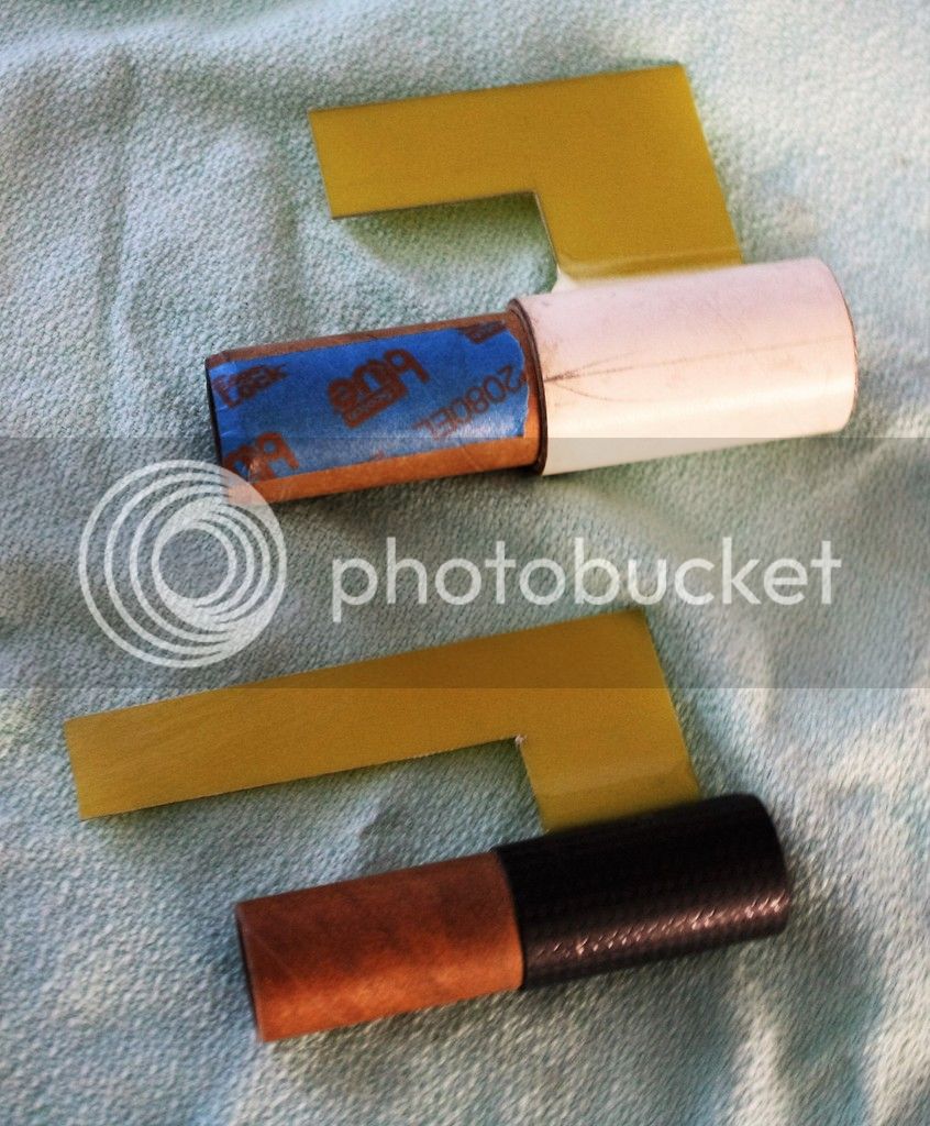
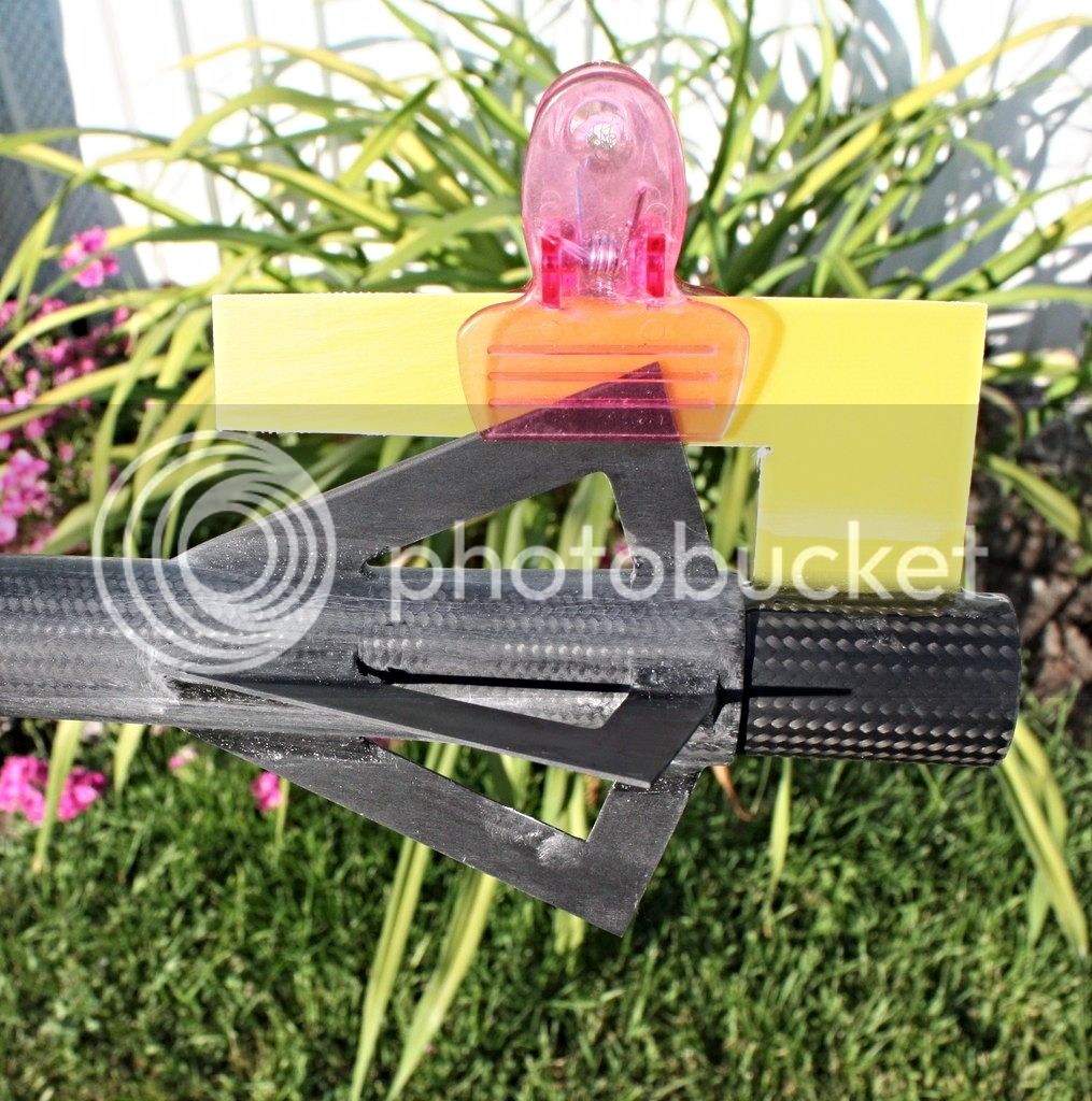
something I cobbled up to get and hold ttw fins straight while the epoxy cures, rotate the tube until the slot/bottom of the fin lines up with the square and the craft sticks will take care of the top of the fin.
Rex

finjig.jpg
 
I came up with this from Rex's post. I've been doing MD. And What I call almost MD. I needed something to hold fins while I epoxy them on The first one is a BT-55 tube with the coupler . Then the 29mm tube fits inside of that. With a 29mm couple to run up into the motor tube on the rocket. In the picture the top one would be used for the rockets with a 29mm mount,

I'm sure you could do the same with any rocket, Just get a short body tube and slot it for the fiber glass, Making sure it's straight. buy some full lenght coupler tube and cut it to length.
24mm fin clamp.
 
Last edited:
Not to derail, but does anyone have a manual lathe-type jig? I'm imagining holding the tiny bit (#80) in place and rotating the workpiece while slowly moving it into the tool, but.... maybe someone has done this before?
 
Not to derail, but does anyone have a manual lathe-type jig? I'm imagining holding the tiny bit (#80) in place and rotating the workpiece while slowly moving it into the tool, but.... maybe someone has done this before?

I'm trying to picture what your doing? What no drill press?
 
I'm nearly finished with my Lathe made from odds and ends, and today made the center stock and did some mock up:

Lathe  Almost Done 2016-07-16 017.jpgLathe  Almost Done 2016-07-16 018.jpgLathe  Almost Done 2016-07-16 020.jpgLathe  Almost Done 2016-07-16 019.jpgLathe  Almost Done 2016-07-16 023.jpg

:D

ETA: Today I'll drill the ends of the box and through the bottom of the center stock, so it can be positioned and held in any location of the bed by a length of all-thread. I'll make a proper base for it out of whatever too.
 
Last edited:
For sanding blackshaft and fiberglass tubes I made a sort of lathe using an old sewing machine motor, scrap wood and a bit of hardward. will handle up to 36" long tubes down to T2 size (with adaptor and internal mandrel). Basicly for 13mm, 18mm and 24mm Black Shaft phenolic tubing it works like a charm on primed craft tubes BT-5 & up tubes without internal mandrels, leaving the tube with a babies butt smooth finish on just about any size tube I can make a tail stop mandrel for....so any size to about 4 inch.

Several years ago I was ask to design a Cheap and Dirty lathe that just about anyone could build using common or scrap wood and an old 1/2" Drill or 1/4hp electric motor.
What I came up with was a 4-1/2" x 32" All scrap wood assembled Lathe using an old 1/2" Cheapy Drill motor as the power. Live and Dead Centers are simply sharpened bolts. The tricky but most important part however is the tool rest. it again is made with scrap masonite with a clear 1/4" lexan adjustable head. the Lexan could just as easily been 1/4" hardboard or plywood but I had a scrap piece of Lexan window covering.

Homemade Lathe-c1-sm_ 1st semi live center_12-13-03.jpg

Homemade Lathe-c2-sm_Centers 1&2 in tailstock_12-13-03.jpg

Homemade Lathe-c4-sm_Centers 1&2 parts_12-13-03.jpg

View attachment Homemade Lathe-d3-sm_#5 long .5in dowel mount_12-13-03.jpg

Homemade Lathe-e2-sm_6in tool rest in use_12-13-03.jpg
 
Here are some totally-custom jigs for specific purposes. For my Madcow 4" FG Nike Smoke the fins came totally flat, I wanted to give them the 'modified diamond fin' look.

View attachment 290434

So I created and printed 6 trays, each one holding the fin at a specific angle with full support underneath (hence why 6 were needed, one for each face). This was done by first making a model of the fin in stages, then subtracting it from trays that angled each fin to make the desired surface even with the top opening. Then using a circular sanding pad attached to my drill press I was able to sand each one to level. The first step on each side was to make the tip a bit thinner than the root (only a very slight angle here), then the remaining steps were to do the leading and trailing faces (steps 4 and 6 could take both sides of the fin to ensure everything was even). I learned as I went and kept refining the .scad file used to generate all of the trays, I didn't re-print the ones I had already used but the current file would print the best version of each one. For example I wound up adding notches at the root/tip ends to remind me just where the beveling should start (I ran a strip of blue tape to help delineate that edge), and adding holes (first to make it easier to pop the fin out then to also reduce the amount of material used), and eventually embedding the step number in the trays rather than writing it on.

View attachment 290438

Here's an example of one of the trays with the fin before and after sanding (this was either the first or second step).

View attachment 290439View attachment 290440

Turned out pretty well I think, though I made the leading/trailing edges fine enough that they're a bit sharp and possibly fragile, it came with a rather large chute though so I'll hopefully get rather soft landings with it. I should make four sleeves to help protect the fins (and to protect ME from the fins) during handling/transport/etc.

View attachment 290441


That is pretty slick.
 
I got the idea for thus years ago when my Pro38s wouldn't fit in my 29mm motor mounts.
Use a 1/4" all thread in where the pilot bit use to go.
Make discs that fit inside the tube and a hole saw the size to grind out the old motor tube.
When you get to the next centering ring, stop, install the next hole saw for the bore size that fits your new, larger motor tube.
It takes a lot of removing and then cleaning out loose material you're cutting.
This one was for my Patriot 4" mount.
Epoxy new motor tube and instal...
Let dry and Fly!

1490142661907.jpg
 
I bought a used rocket that had a one-of-a-kind altimeter bay. Doesn't work with my unified Slimline av bay.
Break out my motor tube boring tools.
Bored it to the right size with an old bulk plate as a template guide.
Epoxy in the new avbay module, done!

1490143430747.jpg

1490143468420.jpg

1490143496098.jpg

1490143532877.jpg
 
I had these parts for many years before I knew what a "tubeless motor mount" was, using just centering rings and rods connecting them.
This 9 " Patriot I designed for a 98mm motor tube and Aeropak retainer.
Then I made a 3" motor tube adapter with its own retainer. The large retainer locks in the adapter.
I got a good deal on an unused Kosdon 4" motor hardware set for EX. Had no idea it is larger in diameter than 98mm AT and CTI cases.
Bored the inside of the 98mm Aeropak to fit the Kosdon case.
I got out the boring tools (from above) again and now the rocket takes all 3" and 4" motors.

1490143920618.jpg
 
I got tired of piling the rockets on the trailer floor. Tired of loading up, trip over them, then having to move them outside, what a pain.
I simply call this The Rocket Rack. You can load them from either end, use bungee cords to hold them in place.
Now I only have to pull the ones out that fly next.

1491353628214.jpg
 
I got tired of piling the rockets on the trailer floor. Tired of loading up, trip over them, then having to move them outside, what a pain.
I simply call this The Rocket Rack. You can load them from either end, use bungee cords to hold them in place.
Now I only have to pull the ones out that fly next.

That's far better that what I did. Very nice!


Steve Shannon
 
I got a nice, big table saw but hate wrestling with huge sheets by myself.
I designed this around off the shelf stuff.
2×4 sheets of plywood, you can use 1×6s and 1×4s, easily done with a skill saw. I cut the holes with a jig saw, too lazy to use a router. Don't need a nail gun, get a box of 1 5/8" trimhead screws and battery drill.
 
Last edited:
I thought of making it mobile but here were reasons why not:
1) Im fortunate to use my former race trailer and it's big enough to keep it inside.
2) I designed it with the minimum of plywood so it gains strength by being screwed to the wall and floor. Making it mobile would require more wood and bracing from being torqued during movement.
3) I like the idea of mobility. My tool box and cart is on wheels, (it stays trapped in place) It was convenient working on my dragbike but that was always on asphalt. All the fields I fly are farms that require larger tires for The Rack, it's ok inside.
 
Last edited:
This old scratch build 4" rocket has been up in the shop rack and not flown since 2005, it's time to change all that!
I have a box of arbors, hole saws, extra parts.

It took about 15 min to assemble this boring tool. Most hole saw arbors use 1/4" pilot bits, so just remove it and install a 1/4" allthread, nuts and lock washers.
I actually grind flat spots on the rod where the arbor set screws lie so I can tighten the assembly much better.
Find a holes saw that is close to the OD of the 54mm MMT and smaller hole saws that fit inside the old 38mm MMT used as guides.
15min Boring tool.jpg


You can remove the retainer and go right at it but I usually cutoff that aft CR so when the new MMT is installed I can do some good fillets from the fins to the MMT.
Cut behind Aft CR.jpg


It cuts right through the fins until it bottoms out in the large hole saw. Withdraw the boring tool and use a 3/4" diameter diamond cutting disc to cut around the inside of the old MMT and it falls out.
Another option is to use long needle-nose pliers and rip the pieces out and bore again.
1st cut of old.jpg


This rocket had a short MMT so this was easy. For longer ones, the middle hole saw should be the same size as the OD of the old MMT.
That jig grinds away the old MMT and cuts the prep for the new one at the same time. The one on the end stays inside the old MMT as a guide.
Longer jobs require paddle-bit extensions or larger ones depending on the arbor you use.
Boring fins and tube.jpg


Here is the new 54mm MMT installed. Prep the end for your new aft 54mm CR, do your epoxy fillets and a retainer and you are done!!
54mm MMT installed.jpg

This 6" rocket I had bored out 4 -38mm outboards and bored the central from a 54mm to a 75mm MMT
 

Attachments

  • 20180328_223612.jpg
    20180328_223612.jpg
    171.8 KB · Views: 142
Last edited:
Back
Top