Building the Estes Little Joe II: Tips, Tricks, and Modifications

The Rocketry Forum

Help Support The Rocketry Forum:

This site may earn a commission from merchant affiliate links, including eBay, Amazon, and others.
Nozzles - Part Two

Painted the Algol nozzles Gloss White (inside too) and let dry for a day. Masked off the lower part of the nozzles, which remain white, and also masked off the forward lips that goe into the aft centering ring holes. In the photo below, the second nozzle is mostly masked, showing the 1/8” wide red vinyl tape that was used because it was so flexible.
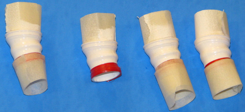
5HpkYsF.jpg


However, when I removed the tape later, it left some red residue. I cleaned it with Alcohol but still have a bit left over. I had tried to use Tamiya's masking tape, yellow 1/4”, but the 1/4” width was too wide to be able to be curved properly around the nozzle. Next time, I think I will test first, and try using “Blenderm” tape as it is quite flexible. But it is about 1” wide, so I’ll have to lay it out onto some clean smooth surface it will not stick to too much (such as “Freezer Paper” which has a shiny side similar to label backing paper), and hand-cut it narrower such as 1/8” or so, maybe 1/4” would work.

Painted the Algol nozzles with Gunship Gray (Tamiya). Let dry a day. Removed the masking tapes from the lower nozzle, then sprayed with Clear Flat and allowed to dry.

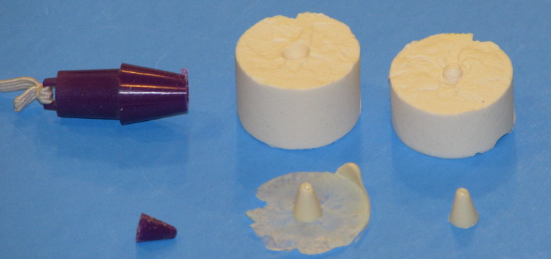
For the Recruit motors, I just wanted to represent them in a simple way, so I did not try to make a scale-accurate nozzle or such. In a junk parts drawer, I found a purple plastic nose cone that probably was from an old Micro Maxx rocket. But I could not find two plastic noses of a suitable shape to cut, just the one. I cut the tip of the nose to use as a nozzle. I embedded the “nozzle” in a bed of clay, in order to make a 2-piece RTV mold, and added keying holes. I placed a 24mm tube into the clay bed to hold the RTV. Mixed up some RTV and brushed some onto the part and into the keying holes, then poured the rest into the 24mm tube. Let cure. After curing, put the mold into a refrigerator to make the clay stiffer due to cold, then later removed the clay and peeled away the 24mm tube. Placed another short piece of 24mm tube over the RTV mold, and used a brush to apply mold release to the nozzle and to al of the exposed RTV so the new RTV half would not bond to the first RTV half. Mixed RTV, poured, and let cure overnight.

Next day, peeled away the 24mm tube, and tried to separate the two pieces along the visible line where the first half ended and second half began. Well, the mold release did not work very well, it did separate but all the keying pins/holes ended up bonding together and ripped, so the mold did not have the keying pins/holes it was supposed to. But, there were enough surface bumps from the tearing to allow aligning the halves anyway. So, I used the mold to cast a couple of nozzles, using Alumilite casting resin.

Left side of the photo below, the original purple nose cone, and cut off tip. Upper middle, the negative half (first half cast) of the mold with a conical hole that creates the outer shape of the nozzle. Upper right, the other half which has a small pointed upward protrusion which molds the inside of the nozzle. Lower middle, raw casting, with flashing. Lower right, cleaned up cast nozzle.
ratoNLw.jpg


Yes, I know most builders of this kit will not get into anything like that. But I’ve documented it anyway, as some may eventually want to try it out for other projects some day. If I had happened to have two small hollow noses of a suitable shape, I would have just cut the tips from the two noses. If I didn’t care for a hollow nozzle, a really simple alternative would be to use a pencil sharpener with a 1/4” dowel, make a sharp point in the dowel, and cut off the tip at the right distance to get the nozzle diameter I wanted. Indeed, until I found that one nose and decided to use that with an RTV mold, I was thinking I would use a pencil sharpened dowel and vac-form the nozzles over it (long ago that is how I made RCS thruster nozzles, vac-formed, before I got into casting with RTV molds and Alumilite). Of course, some folks who are really into modern tech could draw up a nozzle in 3D, and have a 3D printer crank out some.

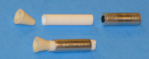
So, with the nozzles created, the rest was easy. In the photo below, one of the nozzles has been glued with CA, into a 5/32” diameter plastic tube. Unfortunately, the next size up of plastic tubing that would slip over would be larger than the 3/16” mount holes. So, I used 3/16” aluminum tubing. In the photo, the 3/16” aluminum tubing is not in final place or glued yet.
lSLDalH.jpg


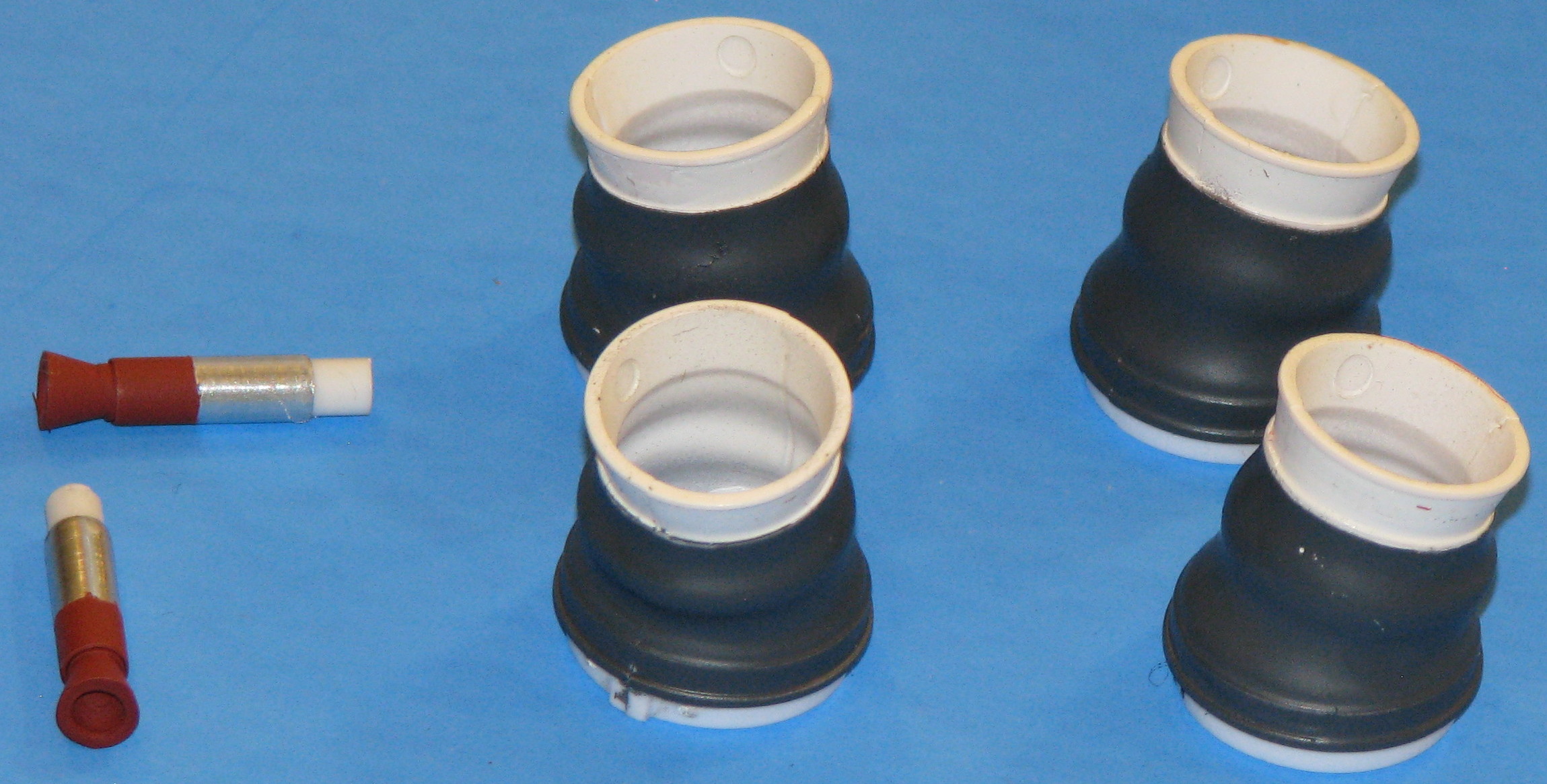
After gluing the parts together, the Recruit nozzle assemblies were painted with a red (rust-brownish) primer which closely matched the color seen in some QTV assembly photos.

An image of the Recruits and Algols after painting.
nXOHBVS.jpg


The Recruits were slid into place in the aft centering ring, and thick CA was applied on the inside to secure them.

With the Recruits installed, I mixed up some 5 minute epoxy to glue the engine mount in place. I used a swab to apply 5-minute epoxy about 3” inside the tube, and to apply a limited amount at the lower end of the tube. I double-checked the drawing to make sure of the proper roll alignment, and slide the mount into place. I inserted the mount at an angle at first to skip over the epoxy on the lower end. Then straightened it up so as I slid it more forward, it made contact with the epoxy deeper inside and slid it into place. After again checking roll alignment, I carefully slid it the last 1/16” so the bottom of the ring would be even with the bottom of the tube.

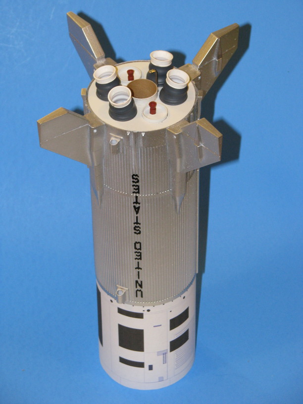
After the epoxy cured, then I put the Algol nozzles in place. Not glued, they are snug enough so that if I wanted to remove and replace an Algol with one of the two unused ones, I could. Actually, the cardboard rings may expand in more humid weather. So, I will apply some of Micro Scale’s Micro Liquitape inside the holes. Liquitape is like a brush-on (can be sprayed on with an airbrush) fine adhesive, stickier than Scotch Tape, not quite as sticky as double-sided foam tape (No I would not recommend it for applying the vac-formed corrugation body wrap). So, the Liquitape will help keep them in place, without being permanently glued. Kind of like using very sticky tape.... but only the adhesive and not the tape.
AxlG9Ia.jpg


And with THAT, the Little Joe-II body is structurally complete! This does not count the improved Service Module wrap or Thruster Quads to be applied later. Also, I plan to add the General Dynamics / Convair plaque decals, but have not made those up yet.

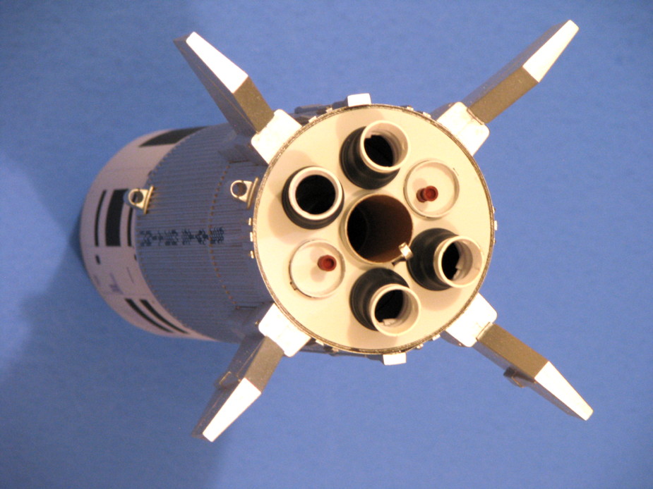
This view makes me realize that a future realism enhancement would be to vac-form (or otherwise create) some nozzle inserts to go inside of the plastic kit nozzles, formed to have a more realistic nozzle throat diameter.
lDEmgE6.jpg


I have glued up the Thruster quads but will cover those later. I need to spend more time on the CM paper wrap drawing, have not yet printed a plain test wrap that even matches the CM cone angle yet, can't add the markings till the wrap shroud is correct.

- George Gassaway
sh2Pzja.jpg
 
Last edited:
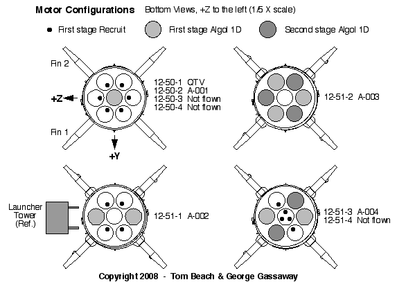
Were there any rounds that used all 6 Algol motors?
 
Were there any rounds that used all 6 Algol motors?

A-003 took off on three Algols, and was going to air-start three more when those burned out. But a roll gyro was hooked up backwards, causing the rocket to roll faster and faster until it broke apart and the abort system successfully saved the capsule in a real (unplanned) abort.

So, it "used" three Algols.... and air-dropped three unused Algols onto White Sands.

Yes, I'm being literal with the word "used". :)

A-003 was the only one to have six Algols installed, which is probably what you meant.

If some of the proposed variants had happened, like the orbital payload concept using a Minuteman missile for stage 2 and 3, some of those variants may have had seven Algols.

Below is a drawing showing the motor configurations for all of the Little Joe-II's.

- George Gassaway

pxqQfwe.gif
 
Last edited:
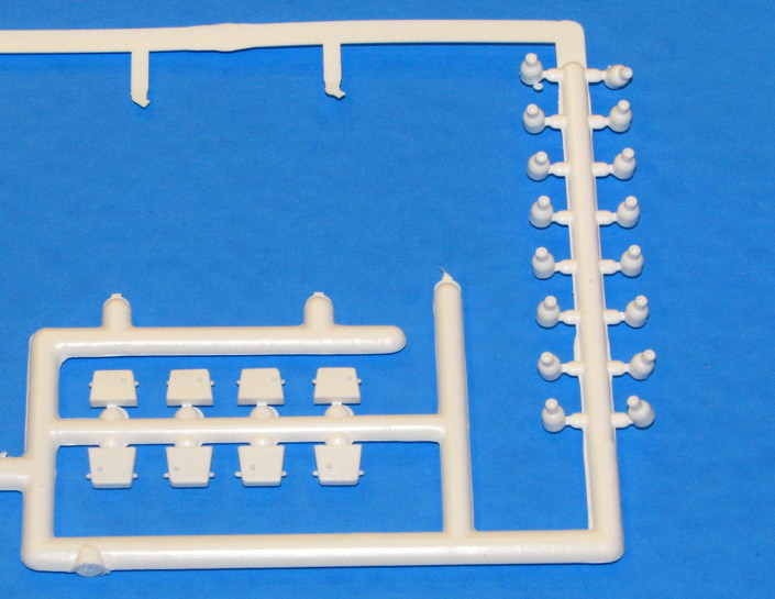
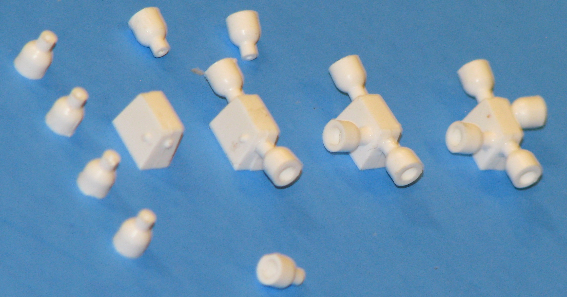
RCS Thruster assembly - I began the process by cutting the parts off the sprue tree.

0vCuKAh.jpg


Rather than cut flush, which is hard to do with the parts on the sprue tree, I left some sprue tabs when the parts were cut off. Then trimmed the remains of the sprue tabs away.

Used Liquid Cement to glue the Quad housing halves together. There are no locator pins, so slide them together so they are even (ensuring that the small external locator pins halves for the thrusters are lined up).

The pins that protrude for the quads sometimes were a little taller than the holes in the thrusters. So after drying, I trimmed the pins to be a little bit shorter.

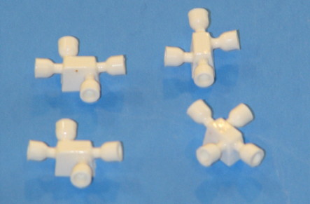
I used Liquid Cement to apply a Thruster to one end. I applied a small drop of the liquid cement inside the hole in the thruster, then pressed into place on the quad housing, centered on the pin. Then used the same method to glue a second thruster to the opposite end. Let dry, and did the other three the same.

txwxi6l.jpg


After allowing an hour to dry a lot, I used Liquid Cement to attach one of the side thrusters, then let dry for a bit. Then glued on the 4th thruster to each of the quads. I brushed on some more Liquid Cement along the roots of all the thrusters, to make sure that the plastic bonded together with no gaps.

zGGTkxD.jpg


And that is their current status. I will paint them Flat White, and later will attach them using 5 minute epoxy, after applying the final paper wrap onto the SM and cutting out rectangles from the paper wrap so the thrusters will be glued to the body tube. Not using CA for that as the CA would tend to seep into the paper and discolor it.

Back to the model as a whole…

EWuNcl4.jpg


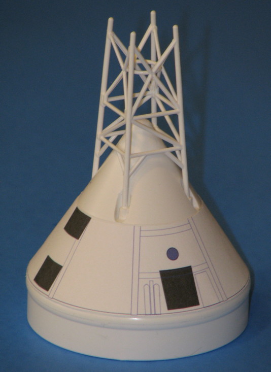
I have a crude CM wrap, but it is simply an old wrap that was resized and not the new one I will be drawing. So, I took a few pics of the model with the prototype/crude wraps on the SM, CM, and LES. The wraps are low-res inkjet printouts. What I will do for the final wraps is to take them to a copy shop and have them photocopied onto paper. The black toner of the photocopy will look much better than the dark gray seen in the pics. Also of course the black toner will hold up better to sunlight and humidity.

- George Gassaway

7JZN8V6.jpg
 
Last edited:
That's looking great George. I have been following this thread with great interest, as I am building one of these right now, too.

I am not looking to make mine as detailed as yours, but I really like the wraps you are making for the SM, CM, and LES. Any chance you could make these available for those of us that want the great detail, but don't have the talent you do?

Thanks for the great build detail and pictures,

Steve
 
I am not looking to make mine as detailed as yours, but I really like the wraps you are making for the SM, CM, and LES. Any chance you could make these available for those of us that want the great detail, but don't have the talent you do?

Thanks. The chances of me posting the wraps are 99%. I already said I plan to.

Other things have gotten in the way of doing the CM wrap (need to do from scratch) and modify the SM and LES wraps. I had expected to be done with them by now.

The 1% of doubt is an issue I have had in trying to get test some wraps to print at the correct size (I am using drawing software well over 20 years old, some files over 25 years old, on a 2004 desktop that can barely run the old software, then convert the modified or new files into a commonly readable format I can put onto a USB drive to transfer to my Laptop). But what the heck, even if the print size ends up as flaky, I probably would post them anyway.

- George Gassaway
 
Still waiting on paint to be delivered so that my LJII model can be completed. Apparently Hobbylinc is using FedEx's new ExpressYak service, resulting in a week-and-a-half transit time from Atlanta to Texas. Grrr......

James
 
Still waiting on paint to be delivered so that my LJII model can be completed. Apparently Hobbylinc is using FedEx's new ExpressYak service, resulting in a week-and-a-half transit time from Atlanta to Texas. Grrr......

James

I bought one from Jon Rocket, it took USPS about week from Orlando to Miami...
It even sent my package to Tampa instead of adding wheels on it and sending it down on I95
 
As I sit here and await the arrival of additional gloss aluminum paint (via mule train, apparently), the decision was made to finish up the capsule/LES assembly. The decals were already in place on the BPC, so next up was the application of the escape tower markings. The thought of applying everything as one large integrated decal made me twitch with fear, so a suggestion offered by Mushtang earlier in this thread was wantonly appropriated: I cut the booger up into six smaller, much easier-to-apply bits. If you elect to do this, the use of a brand new #11 blade is highly recommended. The rendering of the finished model on the front of the kit box was used a reference, so I really hope that picture is accurate.

Micro Set was used to assist decal application, and everything snuggled down nicely onto the gloss paint so no additional solvent agents were required. Plastruct Plastic Weld was used to attach the capsule, tower lattice, and aft skirt assemblies. The directions call for smooshing 3.5 squares of the supplied nose weight clay into the LES motor tube. Using a 1/4" dowel to help persuade the clay into position it only just fit, and the tube is almost completely filled with clay. The remaining clay was smooshed into the capsule peak. Epoxy was then used to attach the LES motor to the aft skirt. After the decals dry for a few hours I'll airbrush the completed assembly with an acrylic satin overcoat to knock down the shine.

IMG_1717.jpg

If you'll excuse me I'm gonna go wait by the mailbox so I can glare at the delivery person when they finally show up with my damn paint.

James
 
As I sit here and await the arrival of additional gloss aluminum paint (via mule train, apparently), the decision was made to finish up the capsule/LES assembly. The decals were already in place on the BPC, so next up was the application of the escape tower markings. The thought of applying everything as one large integrated decal made me twitch with fear, so a suggestion offered by Mushtang earlier in this thread was wantonly appropriated: I cut the booger up into six smaller, much easier-to-apply bits. If you elect to do this, the use of a brand new #11 blade is highly recommended. The rendering of the finished model on the front of the kit box was used a reference, so I really hope that picture is accurate.

Micro Set was used to assist decal application, and everything snuggled down nicely onto the gloss paint so no additional solvent agents were required. Plastruct Plastic Weld was used to attach the capsule, tower lattice, and aft skirt assemblies. The directions call for smooshing 3.5 squares of the supplied nose weight clay into the LES motor tube. Using a 1/4" dowel to help persuade the clay into position it only just fit, and the tube is almost completely filled with clay. The remaining clay was smooshed into the capsule peak. Epoxy was then used to attach the LES motor to the aft skirt. After the decals dry for a few hours I'll airbrush the completed assembly with an acrylic satin overcoat to knock down the shine.

View attachment 282114

If you'll excuse me I'm gonna go wait by the mailbox so I can glare at the delivery person when they finally show up with my damn paint.

James

Mule train? That fast? My first (non-overnight) package from the US was sent in December, here we are in mid February, and it still hasn't arrived. I think the slow boat to China was swapped out for a sea snail.
 
The USPS sloth finally arrived with my gloss aluminum spray lacquer yesterday, so painting of the metallic surface of the airframe was completed. After allowing the paint to cure for a few hours the masking tape was removed, and decal work commenced. Knowing that applying a wide circumferential decal would likely lead to failure accompanied by a colorful and enthusiastic exhibition of profanity, I elected to take Mushtang's suggestion from earlier in this thread and cut the airframe decal into multiple sections. Each of the square roll pattern sections was trimmed to within ~1/32" of the marking border.

IMG_1719.jpg

Note that the line of black circles (representing airframe vents, apparently) have been cut into two sections in this photo, aiming for greater ease of application. After applying the first 180˚ section successfully a decision was made to cut the remainder into two 90˚ sections for even greater ease of handling. Micro Set was used to assist in decal application, and everything snuggled down nicely without needing to resort to more aggressive decal solvent goo.

IMG_1720.jpg
IMG_1721.jpg

Note that the fins have not yet been attached to the model. This was a conscious decision made early in the build process in order to simplify the decal application process. After the decals are applied and a satin overspray airbrushed onto the white surfaces the fins will finally be attached.

More later,
James
 
Last edited:
So AM I the only person on this planet that has flown this New Little Joe II kit?


John Boren
 
So AM I the only person on this planet that has flown this New Little Joe II kit?


John Boren

Well sadly mine is still sitting and waiting for a response from Mike Fritz on a replacement wrap. Because mine was received messed up. Please see pics. Emailed him last week and have still heard nothing back. Also waiting on a response on some JBR013 tubes that were mangled. Can you get someone moving on this John?

https://flic.kr/p/D8ecWe
https://flic.kr/p/E5BX9V

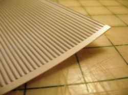
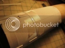
Received two Jbr013 kits both tubes are mangled in the same way. Little Joe II wrap looks like something was drug across the back. Damaging the corrugations. Will definitely show up once painted. Need both replaced asap. Have already sent emails to Mike Fritz
 
Last edited:
Little Joe II wrap looks like something was drug across the back. Damaging the corrugations. Will definitely show up once painted.

You probably won't want to hear this, but that line shows up on each and every one of the vacuform wraps, as it is an artifact of the production process.

Having done a bit of vacuform part production in the past, I immediately recognized that wavy line of marks as the result of tiny holes drilled through the vacuform master in order to allow air to pass through that part of the mold as vacuum is applied during the production process. Estes could send you a thousand replacement wraps and each of them would exhibit the same exact marks. (Perhaps John Boren can provide extra color on the need for the air holes in the master and the overall vacuform production process.)

Don't sweat it, though. Once you get primer and paint on your model the marks pretty much disappear, as you can see from this photo:

IMG_1722.jpg

By the way, I applied the vertical "UNITED STATES" markings to my model last night, and they snuggled down into the corrugations nicely with help from Micro Set and Micro Sol. The solvent was key, and it took about four hours on each side of the model for the process to work.

Again, please note that fins have not yet been mounted on the model. Decal application would have been a complete pain in the ass with the fins in the way, so I highly recommend deferring this step until the end of your build.

James
 
Last edited:
You probably won't want to hear this, but that line shows up on each and every one of the vacuform wraps, as it is an artifact of the production process.

Having done a bit of vacuform part production in the past, I immediately recognized that wavy line of marks as the result of tiny holes drilled through the vacuform master in order to allow air to pass through that part of the mold as vacuum is applied during the production process. Estes could send you a thousand replacement wraps and each of them would exhibit the same exact marks. (Perhaps John Boren can provide extra color on the need for the air holes in the master and the overall vacuform production process.)

Don't sweat it, though. Once you get primer and paint on your model the marks pretty much disappear, as you can see from this photo:


James

That's a great theory but I have also made vac form parts. So I get the process. Two guys that I know locally also have the little joe ii kits. Neither of theirs has the 'artifacts' on their wraps. These are deep enough grooves that they will not disappear with sanding and primer unless I fill up the entire corrugation. Something was clear drug across the back of mine. Went to a local hobby shop that has the little joe ii in stock. Theirs also doesn't have the markings mine does. Thanks for your input though
 
You probably won't want to hear this, but that line shows up on each and every one of the vacuform wraps, as it is an artifact of the production process.

Having done a bit of vacuform part production in the past, I immediately recognized that wavy line of marks as the result of tiny holes drilled through the vacuform master in order to allow air to pass through that part of the mold as vacuum is applied during the production process. Estes could send you a thousand replacement wraps and each of them would exhibit the same exact marks. (Perhaps John Boren can provide extra color on the need for the air holes in the master and the overall vacuform production process.)

I saw those on my first kit wrap, opened kit #2 and saw the wrap had exactly the same.

I would be surprised though if those are vent holes. Simply because their pattern is so irregular. After puzzling over how it might happen, I have three theories:

They are a very tiny bubble of air trapped under each corrugation.

Another would be if it occurred immediately after forming with the plastic hot they were removed too quickly or handled in an odd way such that those would not be bubbles but a sort of crease.

Final theory would be that somewhere along the line from the master mold being produced, and the mass production of the vac-forms, someone made a huge mistake and allowed something to scratch the face of the mold.

At least it is not too noticeable. I can't tell on mine.... but then I used that bad paint. And still these are the best vac-form corrugations I've ever seen, very close to scale, not exaggerated (I loved the Centuri Saturn wraps but they were exaggerated).

BTW - it sounds like what Eric has is an actual serious problem since he compared it with a hobby shop copy, not the minor issue James & I are referring to above.

I want thank BlackJack 2564 (Jim H.) for sending me a couple of 36” Flare parachutes! I had mentioned I flew my old Centuri model with a 36” flare chute Estes used to sell long ago, Jim read that and offered to send me a couple of spares. I’ll use one in this model, as well as an 18” “drogue” on the CM/LES (All connected together). I’ll document the shock cord and chutes in a picture once it’s all done, hopefully a nice descent photo whenever I fly it.

My progress has slowed, juggling other things and working off-and-on with drawings for paper wraps for the BPC, SM, and LES motor. If there was a launch this weekend and the weather was suitable I’d finish it up and fly with draft wraps that I’d replace later.

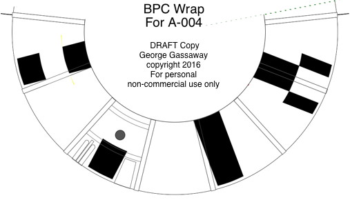
Below is a DRAFT of the BPC wrap. I found out too late that the wrap still does not match the cone angle of the CM, so I need to make some adjustments, which will have a backward ripple effect on the placement of everything else. :( But at least the other things (such as each roll pattern) can be moved and not need to be redrawn.

EocgbAk.jpg


But I figured I’d show the draft so people could see what I’m going for. Some of the lines represent in 2D, some 3D details such as locations of scimitar antenna and vent tunnels near the hatch, and umbilical (I forgot to add a rectangle to represent a second scimitar antenna on the other side, easy to add). What I plan to do once this is complete, is to have 3 copies One with everything. One with the 2D lines removed but keeping the BPC splices and hatch window, and one “smooth” with only the black roll markings.

BTW - I didn’t forget the UNITED STATES lettering and flag. Those indeed were on the CM, as well as a red stripe along the lower portion of the CM, but were not on the BPC.

Also BTW - I found a General Dynamics Font sampler online. https://www.joefino.com/Type_html/T24_General Dynamics.html
It’s not a font file, simply a jpeg of a font file. So, that will help in making a hi-res version of the General Dynamics / Convair plaque.

So, uh, yeah, my model is 90-95% built but waiting for me to do computer stuff to complete it the way I want to. Good thing being that the computer stuff will be useful for future models. And yes I’ll post files for them.

- George Gassaway

g3zSF9q.jpg
 
Last edited:
We're on the home stretch now, and should be done later today! After gluing the motor mount in with epoxy and allowing it to cure, the nozzles were added to the aft bulkhead. Astute viewers will also note that the fins have finally been attached (epoxy).

IMG_1728.jpg

Using the decal drawing that John posted earlier a wrap-around template was created to mark the locations on the SM for the RCS quads. Running a mental flight simulation in my mind I kept envisioning the quads popping off during each flight, and decided that a more secure mounting solution was needed. To that end a small hole was drilled in the back of each quad, and a short length of .025" styrene rod was glued into the hole. After this dries for a bit the quads will be glued into place, inserting the rod through a corresponding hole in the airframe. Once that is dry the extra rod will be trimmed away on the inside of the airframe tube.

IMG_1727.jpg

The quads will still probably pop off, but at least I'll feel better about it until then.

More in a bit,
James
 
The finishing touches are complete on the Little Joe II model! The RCS quads have been added, after which the lower portion of the airframe was masked so that the SM portion could be sprayed with a satin overcoat from an airbrush. A product called Parafilm was used to mask off the dividing line between the two sections. Parafilm is a wax-based film that can be stretched to allow it to conform to irregular surfaces easily, and can be purchased from MicroMark:

https://www.micromark.com/parafilm-m,7551.html
IMG_1729.jpg

A warning: Parafilm should be used only when spraying acrylic paints, as the solvents found in enamel or lacquer paints will melt the wax (buy me a beer and ask me how I know). In this case the satin overcoat used was a Pactra acrylic product, unfortunately long discontinued. A good contemporary replacement would be the Testors CreateFX satin acrylic overcoat, which is probably the same stuff in a different bottle:

https://www.hobbylinc.com/htm/tes/tes79501.htm

As a reminder, I generally try to avoid dead flat finishes on model rockets, as these surfaces tend to become magnets for dirt, grime, ejection debris, and other spoob to which model rockets tend to fall victim. A satin finish is a good alternative as it will knock down the shine of a gloss finish, protect the decals, and generally "tie the room together*." The completed BPC/LES assembly was also sprayed with the satin overcoat, but required no additional masking.

Here's the Parafilm in place:
IMG_1731.jpg[

A plastic wrap was also attached to the Parafilm to protect from any stray overspray:
IMG_1730.jpg

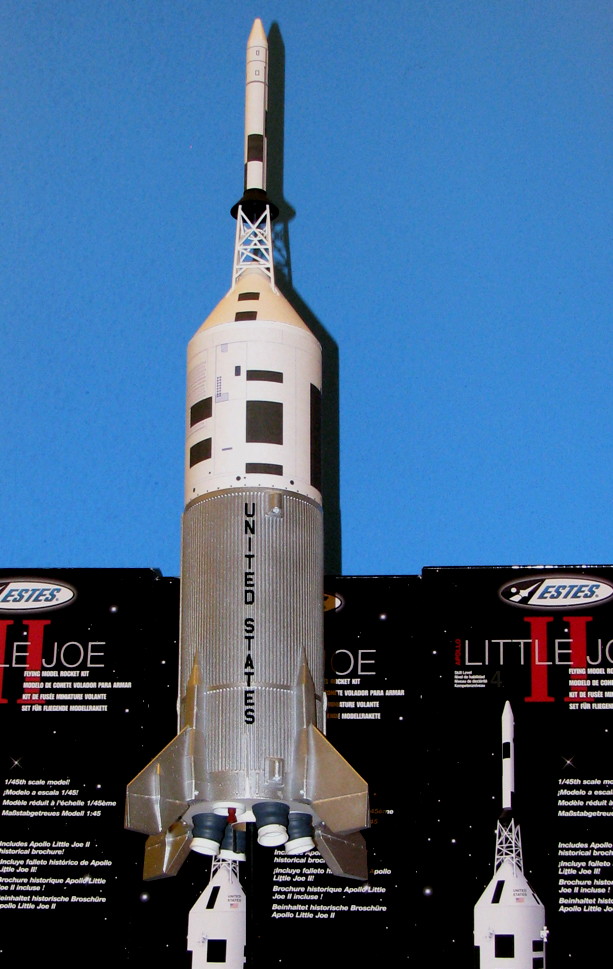
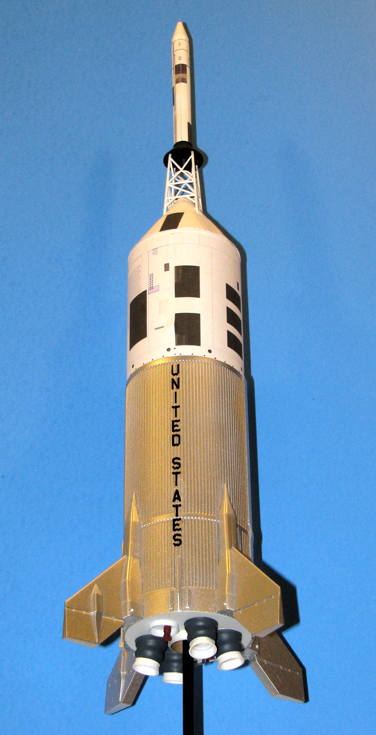
With the masking removed, here's the completed model:
IMG_1732.jpg

Only on one previous occasion have I enjoyed building from a kit more, when I tackled the Estes/NCR X-Wing Fighter. John and the rest of the folks at Estes are to be commended for providing such a wonderfully executed kit, especially one that was a complete surprise. Hopefully this kit will be a financial success for the company and we will continue to see more exceptional releases from the company in the future!

Come join us at the Austin Area Rocketry Group launch on March 5 if you'd like to see it fly.

James
_______________________

*
jeff-bridges-800.jpg
 
Excellent model, Dude!

:wave::wave:

The thruster quads, always an issue. IIRC on my old one, sometimes a thruster broke. Do not recall how often a whole quad was lost, but that happened too. Sometimes the broken thrusters were from transportation damage. So, at least we can warn people to be more careful about packing for transportation. I'll just be wrapping the main Joe in some plastic sheet for general protection of the model's surface and finish, and putting some bubble wrap loosely around it, then into a suitably sized cardboard box for it.

Other times the damage was right after ejection, from the shock cord "raking" along a thruster, so a nozzle (possibly a quad) fell from the sky was was lost. Other times, broken on landing. So always a good thing to check the model for damage right where it lands, in case pieces broke off, so you can look for the parts where it landed (Universal procedure, not just for this kit and not just for scale).
 
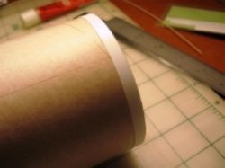
Step 4 - As the short tube at the base dried, I added a step. The top of the body wrap will have a gap of about .015” between the body tube and the top of the wrap. So, I filled it with a 1/8” strip of .015” plastic. Poster paper would also be an option, that is about .015”. What I did was apply 1/2” double-sided tape along the side of a sheet of .015” plastic, then used a metal ruler as a guide to cut the plastic to 1/8” wide. I later wished I’d cut it to 3/32” wide. In the photo below, a 1/8” wide strip is shown held by hemostats… i was originally going to use a spray adhesive. After the pic was taken, and changing to a plastic strip with double sided tape, then the strip was applied to the tube , to fill the gap that the top of the corrugated wrap would otherwise leave.
- George Gassaway

George,

You mentioned in your post that you wished that you would have cut the 1/8" wide styrene filler strip to 3/32". Was that a typo? Did you actually mean 3/16" and not 3/32"? 3/16" is the about the thickness of the "ring" at the top of the corrugations. The reason I ask is am currently at this step in the build process.

Thanks for the great posts!

Paul
 
Last edited:
George,

You mentioned in your post that you wished that you would have cut the 1/8" wide styrene filler strip to 3/32". Was that a typo? Did you actually mean 3/16" and not 3/32"? 3/16" is the about the thickness of the "ring" at the top of the corrugations. The reason I ask is am currently at this step in the build process.

I did mean 3/32" but failed to say why. I wanted to leave a bit more of a margin for error so that if the strip or wrap was a bit off, that the strip could end up below the upper lip of the wrap, and not be forced to be above the lip of the wrap. I'd rather have a slight gap at the top of the wrap to deal with, than a 2-step of the top of the wrap then an upward protruding edge of the filler strip.

Do take note that based on James Duffy's notes about the kit-provided rear ring that has a gap cut out and used as a filler at the bottom, that ring is a bit too thick, should be more like .010 than .015", as it causes a gap at the bottom. So the top filler strip perhaps should be .010" too. Although I did use .015" plastic for that top filler strip and it was OK.
 
Last edited:
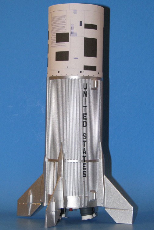
I decided to cut down a strip of 0.015" thick x .250" wide Evergreen StripStyrene to 3/16" and glue it directly to the back of the wrap and not to the tube first. My reason was that I wouldn't have to worry about gluing the strip on the tube in the wrong place. I also used the 0.015 x .250" Styrene at the bottom of the tube in lieu of modifying the cardboard tube as James mentioned. Here are a few pics of my build so far.


3/16" striped glued to the back of the wrap.


1/4" Styrene stripe glued to the bottom of the tube.


Wrap On! You can see I got the wrap a little off.. Oh well...

Paul
 
Last edited:
Wrap On! You can see I got the wrap a little off.. Oh well...

That's a pretty insignificant alignment error, so let's round up and call it "perfect." The long cable raceway will cover it up anyway.

Looks great. Keep the updates coming!

James
 
The thruster quads might stay on better if you drilled a hole for the diameter of a normal headed straight pin.....you could cut about 3/16" or so of the top of the pin, including the head, drill the appropriate hole in the BT and in the thruster quad and install the pin from inside the tube, so that the head cannot easily pull through the BT wall. Installing the pin head from the inside of the BT will be faintly annoying, but certainly doable.

Think I will do that on mine.

I have used that trick on a few other models, both for work and for rockets and R/C aircraft where I need a strong anchor in a thin surface with limited gluing area.
 
I decided to cut down a strip of 0.015" thick x .250" wide Evergreen StripStyrene to 3/16" and glue it directly to the back of the wrap and not to the tube first. My reason was that I wouldn't have to worry about gluing the strip on the tube in the wrong place.

GREAT IDEA!!!

The one thing I wonder about though is after gluing, if that thicker area may not want to curl the same (thicker meaning thickness of the vac-wrap plus .015" styrene). A strip from poster paper might curl easier since the paper can compress more easily inside of the curl.

So, it didn't seem to be a significant problem when curling?

Next models I make, I'm going to use your trick, glue the strip to the upper lip of the vac-formed wrap.

The thruster quads might stay on better if you drilled a hole for the diameter of a normal headed straight pin.....you could cut about 3/16" or so of the top of the pin, including the head, drill the appropriate hole in the BT and in the thruster quad and install the pin from inside the tube, so that the head cannot easily pull through the BT wall. Installing the pin head from the inside of the BT will be faintly annoying, but certainly doable.

Another great idea! I have been considering drilling a hole into the tube and the base of the quads. But for the purpose of gluing a short piece of music wire into the quad base first, then gluing the quad to the tube, with some of the music wire inside the tube, adding some glue to help secure it. But I was not liking the idea of how the wire and CA blobs might snag something. Your idea is minimally invasive, just the thickness of the head of a pin, much better way to do that. No, PERFECT way to do that. :)

The one tip I'd add to that is to rough-up the last 1/8" or so of the end of the pin that goes into the hole drilled into the quad base, to give thick CA a better surface to grab onto. As the super-smooth surface could allow it slip free. I'd have done that with music wire too. Lightly touching the surface with a Dremel tool with a cut-off wheel on it is my favorite way to roughen-up metal for such purposes. In this case easiest to roughen up the pin before cutting it, then when time to cut use diagonal cutters to produce a deformed-squashed (almost barbed) end rather than cut off with the Dremel as I usually would.

- George Gassaway
 
Last edited:
Once I glued the thin styrene strip on the top the wrap did curl a bit, but it did not present any problems. I glued in on the strip with Super 77 3M spray. By using the same thickness styrene on the top and bottom of the wrap it did not leave any gap at the seam. When it comes to building I tend to over-worry. Sometimes my "great idea" turn out to not so great. There can be a good reason no one else didn't like that before.

My next idea is to some how vacuform a BPC cover (difficult) and some radiator panels (easy).

Paul
 
The one tip I'd add to that is to rough-up the last 1/8" or so of the end of the pin that goes into the hole drilled into the quad base, to give thick CA a better surface to grab onto. As the super-smooth surface could allow it slip free. I'd have done that with music wire too. Lightly touching the surface with a Dremel tool with a cut-off wheel on it is my favorite way to roughen-up metal for such purposes. In this case easiest to roughen up the pin before cutting it, then when time to cut use diagonal cutters to produce a deformed-squashed (almost barbed) end rather than cut off with the Dremel as I usually would.

- George Gassaway

I have found that simply gently creasing/crimping the pin every 1/32" or so with a pair of wire cutters along the length of the pin that needs to be bonded works as well as trying to sand or grind it. If installed with CA into plastic, it will take pliers to remove it. The glue in the crimps and creases will really hold it.
 
Back
Top