- Joined
- Jan 17, 2009
- Messages
- 5,204
- Reaction score
- 1,547
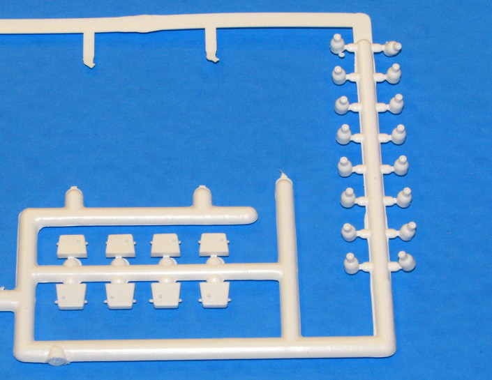
Nozzles - Part Two
Painted the Algol nozzles Gloss White (inside too) and let dry for a day. Masked off the lower part of the nozzles, which remain white, and also masked off the forward lips that goe into the aft centering ring holes. In the photo below, the second nozzle is mostly masked, showing the 1/8” wide red vinyl tape that was used because it was so flexible.
However, when I removed the tape later, it left some red residue. I cleaned it with Alcohol but still have a bit left over. I had tried to use Tamiya's masking tape, yellow 1/4”, but the 1/4” width was too wide to be able to be curved properly around the nozzle. Next time, I think I will test first, and try using “Blenderm” tape as it is quite flexible. But it is about 1” wide, so I’ll have to lay it out onto some clean smooth surface it will not stick to too much (such as “Freezer Paper” which has a shiny side similar to label backing paper), and hand-cut it narrower such as 1/8” or so, maybe 1/4” would work.
Painted the Algol nozzles with Gunship Gray (Tamiya). Let dry a day. Removed the masking tapes from the lower nozzle, then sprayed with Clear Flat and allowed to dry.
For the Recruit motors, I just wanted to represent them in a simple way, so I did not try to make a scale-accurate nozzle or such. In a junk parts drawer, I found a purple plastic nose cone that probably was from an old Micro Maxx rocket. But I could not find two plastic noses of a suitable shape to cut, just the one. I cut the tip of the nose to use as a nozzle. I embedded the “nozzle” in a bed of clay, in order to make a 2-piece RTV mold, and added keying holes. I placed a 24mm tube into the clay bed to hold the RTV. Mixed up some RTV and brushed some onto the part and into the keying holes, then poured the rest into the 24mm tube. Let cure. After curing, put the mold into a refrigerator to make the clay stiffer due to cold, then later removed the clay and peeled away the 24mm tube. Placed another short piece of 24mm tube over the RTV mold, and used a brush to apply mold release to the nozzle and to al of the exposed RTV so the new RTV half would not bond to the first RTV half. Mixed RTV, poured, and let cure overnight.
Next day, peeled away the 24mm tube, and tried to separate the two pieces along the visible line where the first half ended and second half began. Well, the mold release did not work very well, it did separate but all the keying pins/holes ended up bonding together and ripped, so the mold did not have the keying pins/holes it was supposed to. But, there were enough surface bumps from the tearing to allow aligning the halves anyway. So, I used the mold to cast a couple of nozzles, using Alumilite casting resin.
Left side of the photo below, the original purple nose cone, and cut off tip. Upper middle, the negative half (first half cast) of the mold with a conical hole that creates the outer shape of the nozzle. Upper right, the other half which has a small pointed upward protrusion which molds the inside of the nozzle. Lower middle, raw casting, with flashing. Lower right, cleaned up cast nozzle.
Yes, I know most builders of this kit will not get into anything like that. But I’ve documented it anyway, as some may eventually want to try it out for other projects some day. If I had happened to have two small hollow noses of a suitable shape, I would have just cut the tips from the two noses. If I didn’t care for a hollow nozzle, a really simple alternative would be to use a pencil sharpener with a 1/4” dowel, make a sharp point in the dowel, and cut off the tip at the right distance to get the nozzle diameter I wanted. Indeed, until I found that one nose and decided to use that with an RTV mold, I was thinking I would use a pencil sharpened dowel and vac-form the nozzles over it (long ago that is how I made RCS thruster nozzles, vac-formed, before I got into casting with RTV molds and Alumilite). Of course, some folks who are really into modern tech could draw up a nozzle in 3D, and have a 3D printer crank out some.
So, with the nozzles created, the rest was easy. In the photo below, one of the nozzles has been glued with CA, into a 5/32” diameter plastic tube. Unfortunately, the next size up of plastic tubing that would slip over would be larger than the 3/16” mount holes. So, I used 3/16” aluminum tubing. In the photo, the 3/16” aluminum tubing is not in final place or glued yet.
After gluing the parts together, the Recruit nozzle assemblies were painted with a red (rust-brownish) primer which closely matched the color seen in some QTV assembly photos.
An image of the Recruits and Algols after painting.
The Recruits were slid into place in the aft centering ring, and thick CA was applied on the inside to secure them.
With the Recruits installed, I mixed up some 5 minute epoxy to glue the engine mount in place. I used a swab to apply 5-minute epoxy about 3” inside the tube, and to apply a limited amount at the lower end of the tube. I double-checked the drawing to make sure of the proper roll alignment, and slide the mount into place. I inserted the mount at an angle at first to skip over the epoxy on the lower end. Then straightened it up so as I slid it more forward, it made contact with the epoxy deeper inside and slid it into place. After again checking roll alignment, I carefully slid it the last 1/16” so the bottom of the ring would be even with the bottom of the tube.
After the epoxy cured, then I put the Algol nozzles in place. Not glued, they are snug enough so that if I wanted to remove and replace an Algol with one of the two unused ones, I could. Actually, the cardboard rings may expand in more humid weather. So, I will apply some of Micro Scale’s Micro Liquitape inside the holes. Liquitape is like a brush-on (can be sprayed on with an airbrush) fine adhesive, stickier than Scotch Tape, not quite as sticky as double-sided foam tape (No I would not recommend it for applying the vac-formed corrugation body wrap). So, the Liquitape will help keep them in place, without being permanently glued. Kind of like using very sticky tape.... but only the adhesive and not the tape.
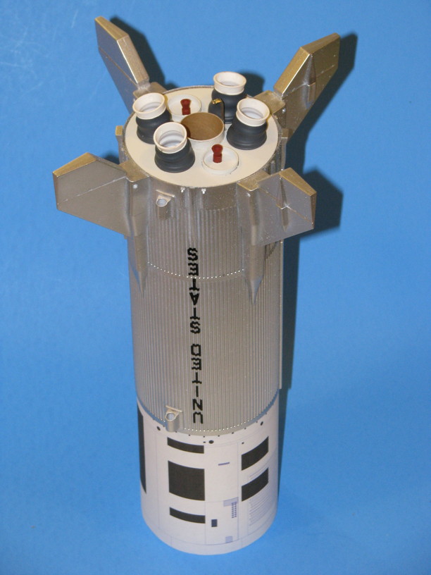
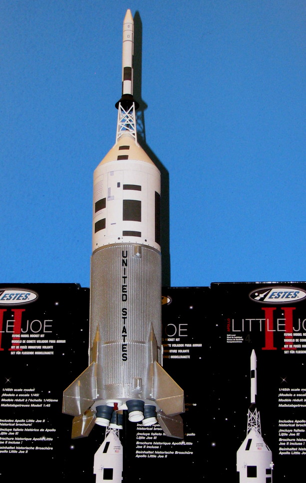
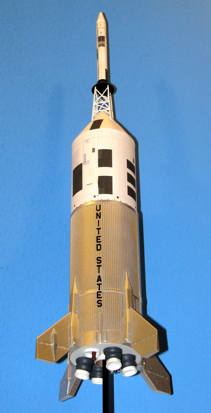
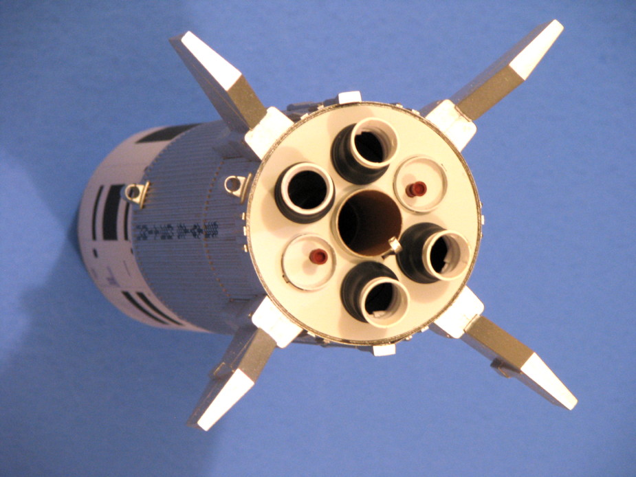
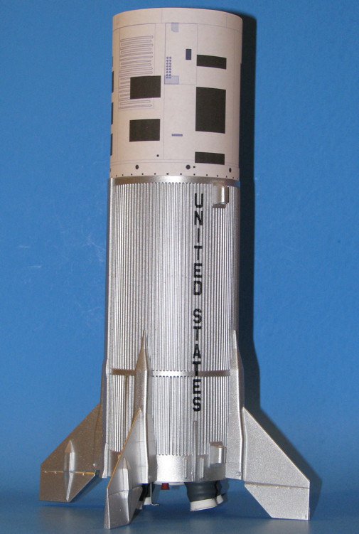
And with THAT, the Little Joe-II body is structurally complete! This does not count the improved Service Module wrap or Thruster Quads to be applied later. Also, I plan to add the General Dynamics / Convair plaque decals, but have not made those up yet.
This view makes me realize that a future realism enhancement would be to vac-form (or otherwise create) some nozzle inserts to go inside of the plastic kit nozzles, formed to have a more realistic nozzle throat diameter.
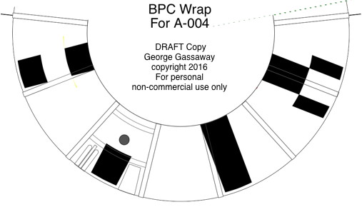
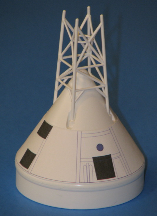
I have glued up the Thruster quads but will cover those later. I need to spend more time on the CM paper wrap drawing, have not yet printed a plain test wrap that even matches the CM cone angle yet, can't add the markings till the wrap shroud is correct.
- George Gassaway
Painted the Algol nozzles Gloss White (inside too) and let dry for a day. Masked off the lower part of the nozzles, which remain white, and also masked off the forward lips that goe into the aft centering ring holes. In the photo below, the second nozzle is mostly masked, showing the 1/8” wide red vinyl tape that was used because it was so flexible.
However, when I removed the tape later, it left some red residue. I cleaned it with Alcohol but still have a bit left over. I had tried to use Tamiya's masking tape, yellow 1/4”, but the 1/4” width was too wide to be able to be curved properly around the nozzle. Next time, I think I will test first, and try using “Blenderm” tape as it is quite flexible. But it is about 1” wide, so I’ll have to lay it out onto some clean smooth surface it will not stick to too much (such as “Freezer Paper” which has a shiny side similar to label backing paper), and hand-cut it narrower such as 1/8” or so, maybe 1/4” would work.
Painted the Algol nozzles with Gunship Gray (Tamiya). Let dry a day. Removed the masking tapes from the lower nozzle, then sprayed with Clear Flat and allowed to dry.
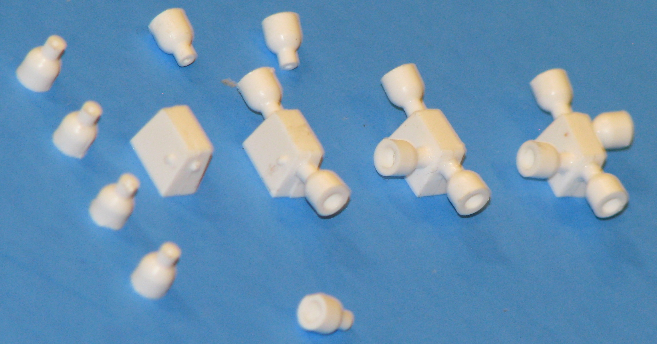
For the Recruit motors, I just wanted to represent them in a simple way, so I did not try to make a scale-accurate nozzle or such. In a junk parts drawer, I found a purple plastic nose cone that probably was from an old Micro Maxx rocket. But I could not find two plastic noses of a suitable shape to cut, just the one. I cut the tip of the nose to use as a nozzle. I embedded the “nozzle” in a bed of clay, in order to make a 2-piece RTV mold, and added keying holes. I placed a 24mm tube into the clay bed to hold the RTV. Mixed up some RTV and brushed some onto the part and into the keying holes, then poured the rest into the 24mm tube. Let cure. After curing, put the mold into a refrigerator to make the clay stiffer due to cold, then later removed the clay and peeled away the 24mm tube. Placed another short piece of 24mm tube over the RTV mold, and used a brush to apply mold release to the nozzle and to al of the exposed RTV so the new RTV half would not bond to the first RTV half. Mixed RTV, poured, and let cure overnight.
Next day, peeled away the 24mm tube, and tried to separate the two pieces along the visible line where the first half ended and second half began. Well, the mold release did not work very well, it did separate but all the keying pins/holes ended up bonding together and ripped, so the mold did not have the keying pins/holes it was supposed to. But, there were enough surface bumps from the tearing to allow aligning the halves anyway. So, I used the mold to cast a couple of nozzles, using Alumilite casting resin.
Left side of the photo below, the original purple nose cone, and cut off tip. Upper middle, the negative half (first half cast) of the mold with a conical hole that creates the outer shape of the nozzle. Upper right, the other half which has a small pointed upward protrusion which molds the inside of the nozzle. Lower middle, raw casting, with flashing. Lower right, cleaned up cast nozzle.
Yes, I know most builders of this kit will not get into anything like that. But I’ve documented it anyway, as some may eventually want to try it out for other projects some day. If I had happened to have two small hollow noses of a suitable shape, I would have just cut the tips from the two noses. If I didn’t care for a hollow nozzle, a really simple alternative would be to use a pencil sharpener with a 1/4” dowel, make a sharp point in the dowel, and cut off the tip at the right distance to get the nozzle diameter I wanted. Indeed, until I found that one nose and decided to use that with an RTV mold, I was thinking I would use a pencil sharpened dowel and vac-form the nozzles over it (long ago that is how I made RCS thruster nozzles, vac-formed, before I got into casting with RTV molds and Alumilite). Of course, some folks who are really into modern tech could draw up a nozzle in 3D, and have a 3D printer crank out some.
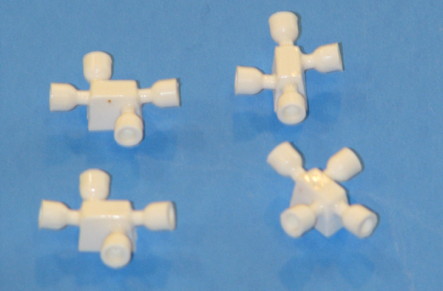
So, with the nozzles created, the rest was easy. In the photo below, one of the nozzles has been glued with CA, into a 5/32” diameter plastic tube. Unfortunately, the next size up of plastic tubing that would slip over would be larger than the 3/16” mount holes. So, I used 3/16” aluminum tubing. In the photo, the 3/16” aluminum tubing is not in final place or glued yet.
After gluing the parts together, the Recruit nozzle assemblies were painted with a red (rust-brownish) primer which closely matched the color seen in some QTV assembly photos.
An image of the Recruits and Algols after painting.
The Recruits were slid into place in the aft centering ring, and thick CA was applied on the inside to secure them.
With the Recruits installed, I mixed up some 5 minute epoxy to glue the engine mount in place. I used a swab to apply 5-minute epoxy about 3” inside the tube, and to apply a limited amount at the lower end of the tube. I double-checked the drawing to make sure of the proper roll alignment, and slide the mount into place. I inserted the mount at an angle at first to skip over the epoxy on the lower end. Then straightened it up so as I slid it more forward, it made contact with the epoxy deeper inside and slid it into place. After again checking roll alignment, I carefully slid it the last 1/16” so the bottom of the ring would be even with the bottom of the tube.
After the epoxy cured, then I put the Algol nozzles in place. Not glued, they are snug enough so that if I wanted to remove and replace an Algol with one of the two unused ones, I could. Actually, the cardboard rings may expand in more humid weather. So, I will apply some of Micro Scale’s Micro Liquitape inside the holes. Liquitape is like a brush-on (can be sprayed on with an airbrush) fine adhesive, stickier than Scotch Tape, not quite as sticky as double-sided foam tape (No I would not recommend it for applying the vac-formed corrugation body wrap). So, the Liquitape will help keep them in place, without being permanently glued. Kind of like using very sticky tape.... but only the adhesive and not the tape.
And with THAT, the Little Joe-II body is structurally complete! This does not count the improved Service Module wrap or Thruster Quads to be applied later. Also, I plan to add the General Dynamics / Convair plaque decals, but have not made those up yet.
This view makes me realize that a future realism enhancement would be to vac-form (or otherwise create) some nozzle inserts to go inside of the plastic kit nozzles, formed to have a more realistic nozzle throat diameter.
I have glued up the Thruster quads but will cover those later. I need to spend more time on the CM paper wrap drawing, have not yet printed a plain test wrap that even matches the CM cone angle yet, can't add the markings till the wrap shroud is correct.
- George Gassaway
Last edited:
")