2 Stage Scale (Sorta) Black Brant IX (Terrier Black Brant) Project

The Rocketry Forum

Help Support The Rocketry Forum:

This site may earn a commission from merchant affiliate links, including eBay, Amazon, and others.

nute

Well-Known Member
Joined
Jun 30, 2013
Messages
2,298
Reaction score
5
Hello all,

This is where I'll be documenting the build and flight progress for my winter project, a 2 stage, quasi-semi scale-iiish Black Brant IX. HPR 2 stage always seemed like the pinnacle of complexity, so naturally I figured I had to attempt it, "not because [it] is easy, but because [it] is hard". This is a project I've been thinking about for a month or so now, mentally working through problems as I find them. I'm hoping to finish it by the end of winter, and fly it sometime in the spring or early summer. Each stage will have a 38mm motor mount.

General Parts:

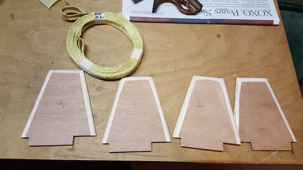
I decided on 2.6" LOC tubing as the happy medium between large (easy to fit stuff) and light (easy to lift). It'll be all scratch, and technically not really scale, but rather a rough approximation of fin shape and general dimensions. I'll be using 3/16 or maybe 1/4" ply for fins, LOC centering rings, motor mounts, couplers, and stiffies, and bulkplates from Madcow. I'm not 100% sure they'll fit perfectly, but their tubing dimensions are within a couple 1000ths of an inch of each other, so I'll take my chances. I'm using the 2.6" ARCAS fiberglass nosecone from Madcow. I like the longer shape much better. I'm not crazy about the additional weight. but I can deal with it. I'll have a tracker bay in the nosecone. The fin slots will be custom from LOC precision, and the fins themselves will be cut here at home, probably with a table saw.

Electronics:

Alright, so the tricky part with two stage is, naturally, the staging. Safety is my primary concern/goal. So the plan is to have an RRC3 in the sustainer taking care of deployment and upper stage ignition, as well as an RRC2+ for backup deployment. The RRC3 will have an altitude-time check for stage ignition, the specifics of which will be determined after final weights are in and the motors have been chosen. There'll be a BRB 70cm RDF tracker in the nosecone.
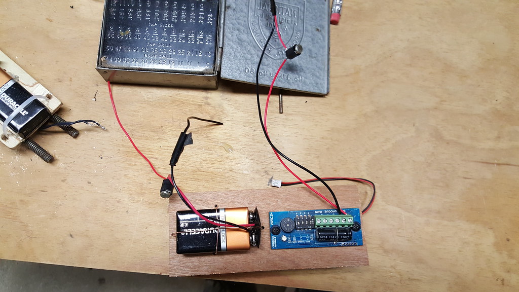
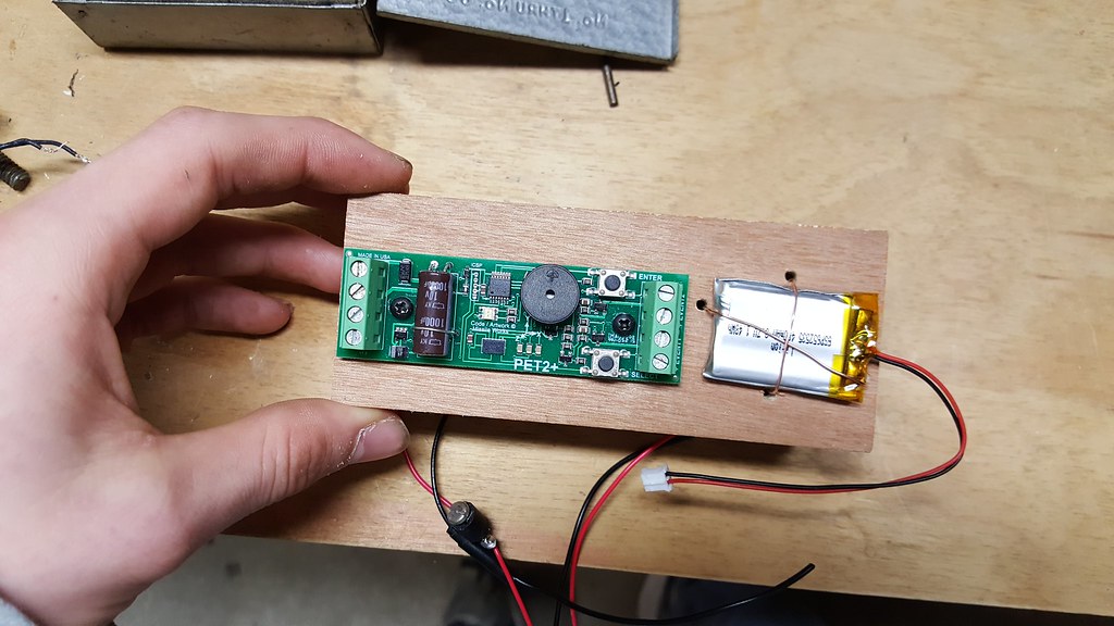
In the booster's interstage I'll have an RRC2+ for deployment, and a Missileworks PET2+ timer firing a separation charge based on a G check. I'll also have a BRB 70cm RDF tracker on the shock cord. Currently, I'm planning single deploy in the booster, but leave room to add a cable cutter for higher flights. I'm thinking I'll use these screw switches from Aerocon. The plan is to mount them semi-flush to the airframe, so I don't have to negotiate two or three switches through vent holes. I'm now thinking I'll also have a switch between the sustainer igniter and the altimeter, so I can power up the altimeter, verify proper function, and only then energize the ignition channel.


Here's a picture of the current plan and an OR file:
Two stage picture.jpg
View attachment Two stage build.ork

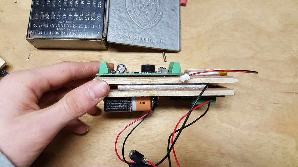
Since I'm not sure 6" will be enough to easily fit 2 altimeters, batteries, and three switches, I'm thinking, in lieu of custom couplers, I'll just splice two together with a stiffy. I think I'll do the same for the interstage coupler, so I can have a bit more length and make the whole shebang a bit stiffer.


Interstage:

I did a lot of thinking about the interstage and came up with an idea I think will work. It's a bit hard to describe, but this is the idea:
the upper three inches or so will mesh into the upper stage, and have the upper stage motor mount pretty much sitting inside it. a bit below that, there will be a short (1/2"?) section of stiffy that will be glued in place. This will act as a stop for the coupler bulkhead that will slide into the coupler and rest on the stiffy. The other side of the bay will be normal.


So I think that's most of it. I've got a couple H550s, an I600, and an I500T on the docket for Wildman's sale tomorrow. All of those should make good boosters. I'm thinking the first flight will be all up, minus an upper stage motor, so I can see how straight it flies, how it separates, and compare data to OR sims, etc. I'm sure I've forgot some details I'll add later.
 

Attachments

  • Two stage picture.jpg
    Two stage picture.jpg
    91.8 KB · Views: 144
Excited to follow this build. Seems like an awesome project and one I hope to learn a bit from by watching!! Good luck! :)

Jim Z
 
It sure sounds like you've thought everything through. ...
This is going to be quite a spectacular rocket to watch fly...
All the best of luck with the details Nate . ...

Teddy
 
This would be cool with a 4" maybe a LOC IV booster to a LOC IV stretch as the sustainer. Might try this some time. I'm watching this thread with interest.
 
I'm building my PML Mini BBX and Terrier two stage right now. That interstage design uses some custom-molded pieces but it works really well, you may want to look at those for inspiration.
 
Thanks for the comments everyone.

Not an update really, but I ordered the RRC3 and PET2+ today. Thanks for the deals Missileworks!

Nate
 
How are you planning to mount the BRB to the harness? I've tried that a couple of time, but it seems pretty hard to keep it from getting damaged.

Jim
 
How are you planning to mount the BRB to the harness? I've tried that a couple of time, but it seems pretty hard to keep it from getting damaged.

Jim

Jim, here's a snapshot from another thread where I showed how I go about doing this. In this example, it's done with a BRB900 unit, but the concept is the same and would work just fine for a 70cmGPS transmitter.


Here's a few pics to show how I go about it:

1st pic: the components- a nomex "pocket" (which I cut out of some fireman's pants I got off E(vil)bay dirt cheap), a piece of kevlar cloth (also a cheapie E(vil)bay find, a second from a ballistics vest), a small piece of soft foam (scrap), some flexible electrical tape, the braided kevlar shock cord, and the BRB900 unit itself.
2nd pic: place the BRB900 on the piece of foam.
3rd pic: wrap the foam around the BRB900
View attachment 274690

4th pic: put foam wrap bundle on piece of kevlar cloth.
5th pic: wrap the kevlar around the foam/BRB900 bundle.
6th pic: place the kevlar/foam/BRB bundle into the pocket.
View attachment 274691

7th pic: when putting bundle into the pocket, pull antenna through small hole cut in corner of pocket.
8th pic: place shock cord over pocket.
9th pic: roll pocket around shock cord.
View attachment 274692

10th pic: do a nice tight wrap of electrician's tape around ends of bundle, and you're good to go. (unless you've forgotten to plug the battery in and turn the unit on - ask me how I know this.)
View attachment 274693

Works fine. Electronics are protected both from ejection charge blasts, and from knocks and bumps. Unit (& antenna) is outside of rocket airframe from apogee all the way down, so much more chance of getting a solid lock and good communication.

There are lots of ways to go about this, but this is one that works for me (of a few different ways I do it myself).

Try it, it will likely work for you just as well,
s6
 
How are you planning to mount the BRB to the harness? I've tried that a couple of time, but it seems pretty hard to keep it from getting damaged.

Jim

Hi Jim, what I've been doing is pretty low-tech. I've been wrapping the transmitter and battery in black electricians tape, and then using a wrap or two of black Gorilla Tape tape it on to the harness, and then putting a small thin wrap at the bottom of the whip antenna to provide a bit of strain relief. Some others at our club have used a similar approach with good results, and I like it for where there's no good spot to hard mount it. I know it's probably not best practice, and I've been thinking about other ideas, namely some sort of plastic container, and I really like S6's nomex pouch idea, I'll have to try that at our next launch. Thanks Stealth!

Nate
 
Progress! I got some good work done today, now that I have the parts after Christmas/birthday. I bought some conduit tubing to use for the sustainer ignition wiring this morning; it took some looking but I found some 1/4" OD stiff plumbing tube.

I removed the glassine from the MMT, and then drilled holes in the CRs for the conduit. I marked the tube for a CR at the top and bottom of the fin slots, and the interstage coupler will butt right up against that ring. The top ring will be at the top of the MMT for the SC attachment.
20151226_154311.jpg

I used wood glue to attach the CRs with fillets on the outsides, and attached the Aeropack with Rocketpoxy. (it's a dry fit in the picture)

20151226_161158.jpg

The booster motor mount got the same treatment, with the CRs mounted to interlock with the fin slots.

20151226_161226.jpg20151226_161705.jpg

I didn't glue on any of the top CRs as I don't have any eye-bolts on hand.

I also cut all of the tubes to length (booster- 22", sustainer payload- 24", and two 1" vent bands) using a razor and carefully marked line. It took a bit of sanding, but I got the fits pretty good, and I might do a bit more touch up later.

20151226_210840.jpg

Next, I cut the sustainer altimeter sleds. I'm using a 5 3/8" sled and a 4 5/8" sled, glued back to back with allthread in between. The shorter will hold two lipos, and the longer will hold the RRC3 and RRC2+. I used 3/16" ply since it was what I had on hand.

20151226_203030.jpg20151226_210758.jpg
I zip tied the batteries down, and they feel quite secure.

Then I realised I hadn't taken an official "parts shot", and laid everything out. A "parts shot with minor assembly complete" will have to do:


20151226_211136.jpg

That's all for now, we'll be out of town visiting family for the next few days, so I'm not sure how much more I'll get done before I go back to school. I'll place an order with doghouse for some AV-bay goodies soon, and find some eye and U bolts, so when I get back I'll be able to keep working on the av-bays and finish up the motor mounts. Then it'll be time to cut the fins! Time to warm up the table saw...

Thoughts and comments welcome.

Nate
 
Well I was gonna post a great weekend update with pictures of the finished motor mounts and fins, but as I was trying out a new fin beveling technique using a disc sander on a radial arm saw I took a pretty grisly hit to two of my fingers even with my Dad's supervision. The disc was at a 20* angle with the fin on the table and my hand on top of it guiding it into the saw. It was going great until the disc kicked the fin up, and my hand followed right into the sanding disc. It was not pretty. A quick trip to the urgent care center and I'm feeling mostly fine, but not really eager to go take pics, etc.
 
Well I was gonna post a great weekend update with pictures of the finished motor mounts and fins, but as I was trying out a new fin beveling technique using a disc sander on a radial arm saw I took a pretty grisly hit to two of my fingers even with my Dad's supervision. The disc was at a 20* angle with the fin on the table and my hand on top of it guiding it into the saw. It was going great until the disc kicked the fin up, and my hand followed right into the sanding disc. It was not pretty. A quick trip to the urgent care center and I'm feeling mostly fine, but not really eager to go take pics, etc.

Glad you're ok! these types of moments are the ones that save fingers and even lives in the future. It's always important to stop and think what could go wrong, and do something to prevent it. Very glad to hear you're ok, and this build looks very cool by the way :) can't wait to see how it turns out.
 
Well I was gonna post a great weekend update with pictures of the finished motor mounts and fins, but as I was trying out a new fin beveling technique using a disc sander on a radial arm saw I took a pretty grisly hit to two of my fingers even with my Dad's supervision. The disc was at a 20* angle with the fin on the table and my hand on top of it guiding it into the saw. It was going great until the disc kicked the fin up, and my hand followed right into the sanding disc. It was not pretty. A quick trip to the urgent care center and I'm feeling mostly fine, but not really eager to go take pics, etc.

I'm glad your O.K.! Just saw this thread, awesome project! :eek: It's one of those designs I've always thought about doing, so I'm quite looking forward to seeing the finished product/flights! Hope you feel better!
 
Oh man Nate,,
I sure hope your OK..
I bet you gave your pop a small heart attack when that happened..
Keep it clean Nate...

Teddy
 
Sorry to hear that Nate. I just saw this build, will be following!
 
Well I was gonna post a great weekend update with pictures of the finished motor mounts and fins, but as I was trying out a new fin beveling technique using a disc sander on a radial arm saw I took a pretty grisly hit to two of my fingers even with my Dad's supervision. The disc was at a 20* angle with the fin on the table and my hand on top of it guiding it into the saw. It was going great until the disc kicked the fin up, and my hand followed right into the sanding disc. It was not pretty. A quick trip to the urgent care center and I'm feeling mostly fine, but not really eager to go take pics, etc.

*Gulp*...every parent's nightmare - my sympathies to you (and your poor Dad). It sounds like it could've been even worse - so you take care, pace yourself and let the fingers fully heal. It's a great project - but, like I say to my own son, please take extra care with the power tools..:) Good luck with the rest of a very interesting build.
 
Well, here are some updates from the past few weeks. I haven't tried beveling any fins again though... But I think I've got a way to do it.

I've been doing work on the AV-bay and motor mounts mostly. I got the RRC3 issue I had sorted out, and I'm feeling much more comfortable with it. Jim Amos was great, very responsive and helpful. Highly recommended.

Anyway,

Motor mounts finished:


I used wood glue and wood glue fillets on all the joints. U bolt was secured with epoxy, and the harnesses are courtesy of Onebadhawk, 1/2" flat kevlar. Great material, very soft and supple. The conduit is held in place with 5 minute epoxy, and fits nicely inside the interstage coupler.

Next up, the sustainer AV-bay:

I realize I didn't take a whole lot of pictures of putting the bay together, but here's what I got:

Bulkhead:


Finished with doghouse charge wells, Missileworks terminal blocks, and wiring from doghouse. I used a 1 1/8" x 1/4" U bolt. It fits well, but had to be slightly offset to allow for both charge wells. Lots of holes, but I like the way it turned out.


All the wiring is color coded: red is main, with orange being backup, and black is drogue, with brown being backup. Green is for the switch. I'll use purple for the upper stage ignition, which I still have to order. The switches will be mounted flush into holes in the body tube, and I'll add a third one in the upper stage firing circuit.
I also got the Pet2+ on friday, so I've been playing with that. I rather like the way it's setup. I was a little concerned having to program with just pushbuttons and LEDs, but the way its laid out is very intuitive after reading through the manual.


And of course the fins. I was going to cut them with the table saw, but the angles were a little too tricky, so some of the initial cuts were done on the table saw, but most of the shorter cuts weer on the bandsaw. Then I retraced the OR fin printout and sanded down the edges with the dreaded sanding disk on the table saw. This was before I screwed up with it. I sanded the fin slots to accept each fin, matched to its slot, and used this little jig to check the tab fit:


And a nice shot of the Pet2+


I'm working on the interstage now, hopefully I can make some good progress today.

Nate
 
Very nice, clean work Nate! Any chance you'll be at the Radrocks launch this weekend? ;)
 
That av bay came out just smokin Nate....
Great work....
And I'm especially glad to hear you're not beveling anymore....lol....

Teddy
 
Well, I do believe it's high time for an update.

I've been working on this project kind of sporadically, in between essays and AP chem tests. So far I've gotten all the fins beveled (without any injuries this time), the booster motor mount glued in, and the interstage mostly completed.


First up: fin beveling. I used our belt sander with 120 grit paper to do all three edges of the fins. I had to do each edge in two halves (big fins, small sander), but they generally turned out okay. There are a couple places with mistakes, but I think that they'll mostly get covered up and fixed in the finishing process.

Here's the end result:


I did the same thing for the first stage fins, which turned out better:


I don't have a picture of the booster motor mount installation. Not really much to look at, but I used liberal amounts of Titebond II before each CR to hold it in place. I used a flash light and could see a fillet that formed on the top CR, so things look good for that.


On to the interstage, which turned out to be a little trickier than anticipated. Originally I planned to put both altimeters next to each other on one side and both batteries next to each other on the other side, much like the upper stage AV-bay, but having to fit everything through the LOC stiffy made things harder. I'm using the stiffy to extend the length of the coupler, since about 3" of the coupler is dead space, being taken up by the upper stage's motor mount wher they mesh. I realize now I didn't take any pictures of that setup, but it was way too tight on the sides to make it past the stiffy. So, I rearranged things so that the larger Pet2+ and 9V were in the middle on opposite sides, each complimented on their side with the RRC2+ or its Lipo, both of which are much smaller:

Side one:


And... side two:

25539376085_2b9932a1db_b.jpg


Ta-da!!

25446629401_5065f7c61e_b.jpg


I also ditched the zip ties in favor of thinner, 20 ga wire. It shaves about 3/16" from between the two sleds. It'll be tricky to change the 9V, but I think I'll be able to thread wire through the holes in the sled.


And the aft Interstage bulkhead:


And fully populated:


And this is when I hit my first "big" problem of the build. The interstage engages the upper stage with 3" of coupling, and the AP from the upper stage pretty much butts up against (within 1/8") the fore bulkhead of the I/S. What I didn't account for was the charge well on that end, which is 1" long :y:. So, I've got a problem. I figure I've only got to use no more than about .5 g of BP to separate the stages (probably less) so I can cut the charge well down to about 1/4" or 3/8", so that gives me almost 3/4". Just gotta make up another .25". I figure the first thing I can do is just give up some of the meshing length, ie only let the stages mesh 2.75". But, from a safety aspect, I'd like to keep as much of that overlap as possible. So next up, well I can move the motor mount up 1/4", but It's already recessed pretty far, and I'd have to modify the structure of the CR or fin slots. So, I figure, maybe I can have a compromise. I can make up part of the 1" by axing part of the charge well, move the MMT forward say 3/16", and then also maybe sacrifice 1/8" or 1/16" of overlap. I figure that should work, and I'll find out soon.


And, I've got a question for everyone regarding upper stage safety. I've read that it's best practice to power up the motor ignition electronics with the motor igniter outside the rocket. So, at the pad, I'll have the rocket apart (upper and lower stages), power up the RRC3, make sure nothing fires, turn it off, put it together and put it on the rail. I've also read that it's a good idea to have the motor ignition channel of the altimeter switched, so the altimeter can be turned on while it's on the rail, verify proper startup, and only then arm the upper motor by closing the switch as the very last thing to do. Does this sound correct? It sounds safe to me, so there are two chances to catch any problems with the altimeter before the motor is actually "hot", and even if there's an on-pad error, the RRC3 will not fire that motor until everything is confirmed working properly. Thoughts?

Probably another update tonight.

Nate
 
Last edited:
Keep up the great work Nate...
I sure can't wait to see this thing fly...
Even though I know it's going to be a perfect flight...lol...

Teddy
 
Back
Top