grouch
Well-Known Member
Fantastic thread Ken! Congrats on the L2, done in style for sure.


Fantastic thread Ken! Congrats on the L2, done in style for sure.
")
 op:
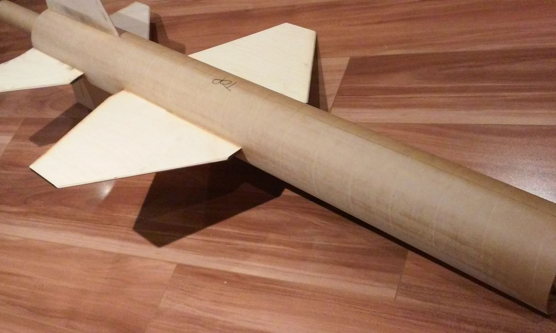
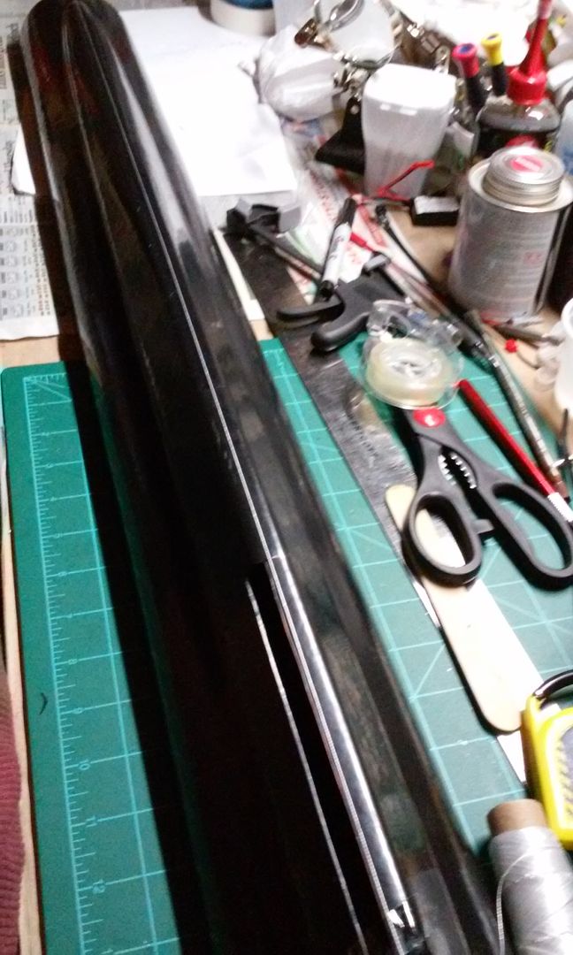
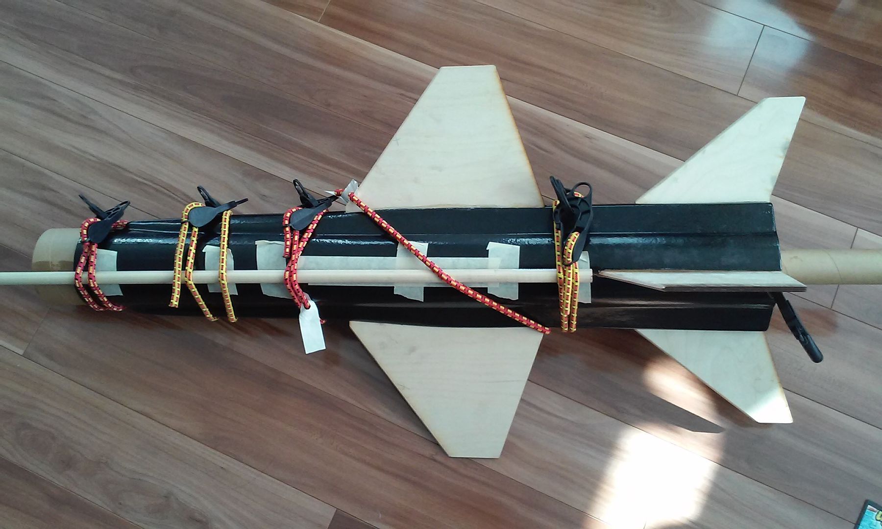
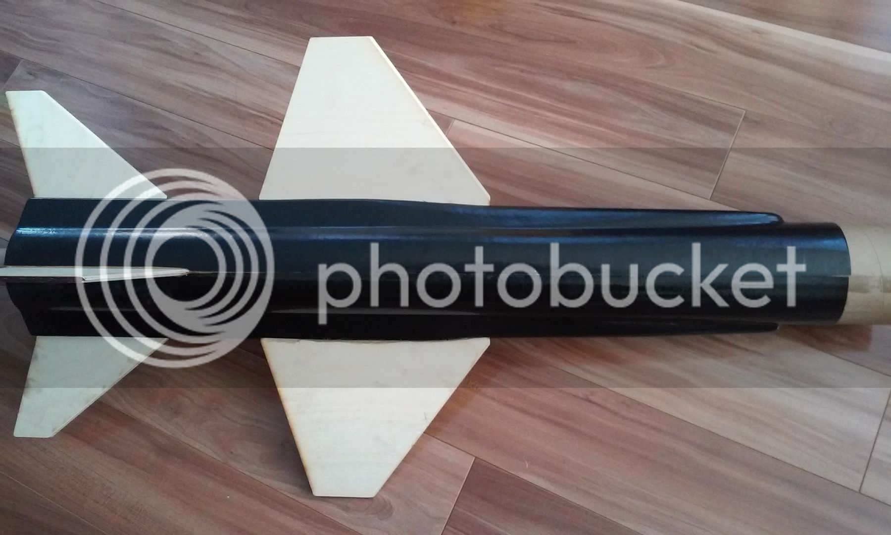
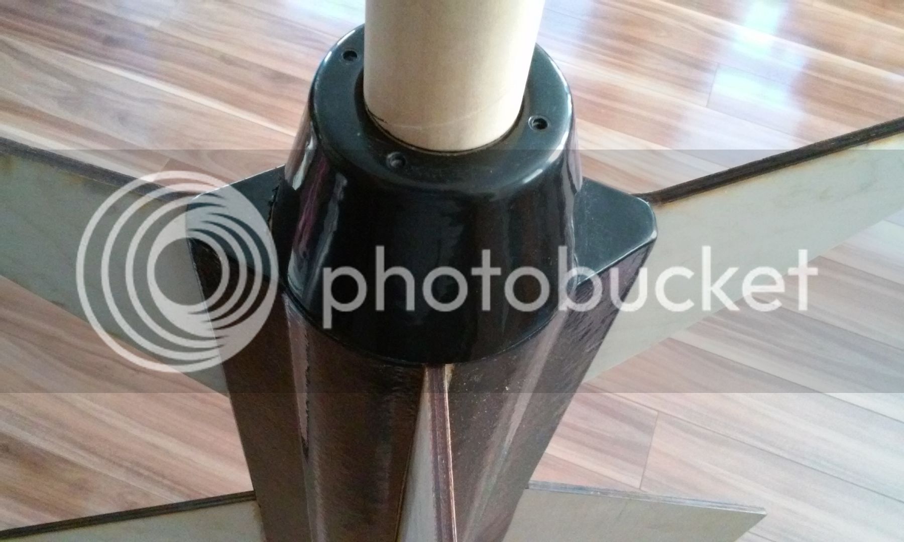
op:I've been considering an upscale clone of this in the 2.6" range with a 29mm MMT. I may forego that idea now since this kit is available. I need to be flying more 38mm anyway.
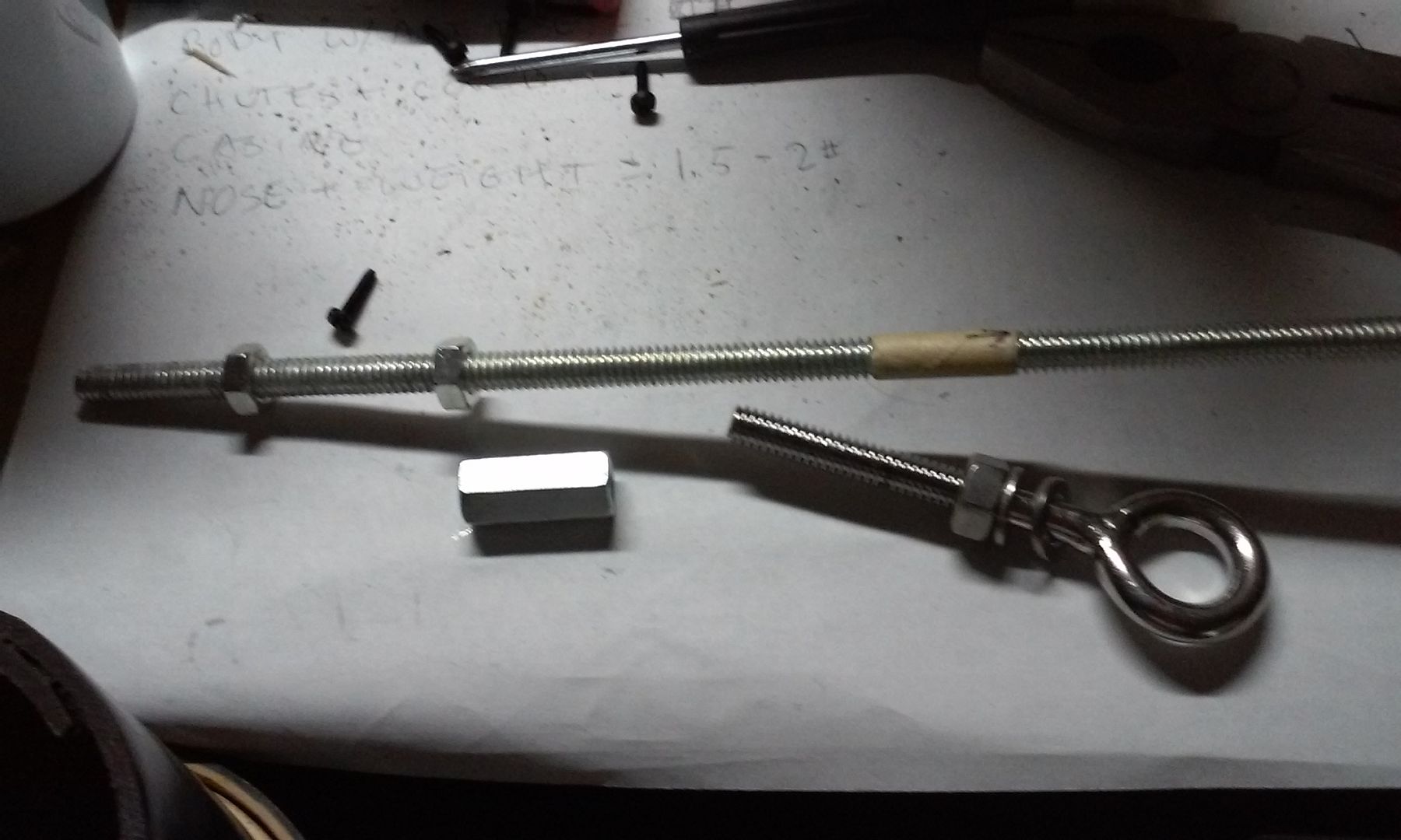
Does anyone have a list of the recommended motors for this kit?
Damn that bird turned out beautiful, great work and congrats on your certification.
Great flight Ken. Way to do L2 in style.


Wow. This is awesome. Look forward to hearing about the flight!
That's what I get for posting when I should have been asleep! I absolutely missed those entries and only focused on the build of the Hanger 11. That is quite impressive!

Enter your email address to join: