Wildman Jr. Two-Stage Mod/Build Thread

The Rocketry Forum

Help Support The Rocketry Forum:

This site may earn a commission from merchant affiliate links, including eBay, Amazon, and others.

smapdiage9

Well-Known Member
Joined
Mar 14, 2009
Messages
442
Reaction score
3
Hello, I am a recently minted L2 who has not yet flown any K or L motors and has also not yet acknowledged the severe cost of propellant in my new impulse range. Given that oversight, I decided to build my first high power two-stager: a Wildman Jr. kit I picked up this summer. And since I happen to have a Pro54 6GXL case kicking around the house, I thought to myself that I might as well make the booster a minimum diameter setup. Because what’s the point of a rocket if it doesn’t teach me to push the limits of my construction techniques?

Oddly the two-stage add on for this kit does not have any instructions on the Wildman website. I used Jim Hendrickson’s post here to guide my construction: https://www.rocketryforum.com/showt...ldman-Jr-kit-to-a-2-stage-build-Vindicator-JR

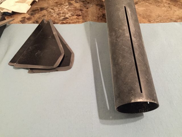
So far every part of this build has been more head scratching than the last. I started with the booster fincan, since it seemed like the most exciting thing to try.
I used my table top belt sander to knock down the fin tabs designed for through the wall mounting, so that my fins would fit flush. Since none of the fin slots on either tube were wide enough for the standard fins, I used a piece of card stock with 60G sandpaper around it to widen the slots. I also beveled the fins by hand a bit, and roughed everything up inside and out:

aB2HWhil.jpg


Next I designed a MD fin guide in Fusion 360:
NOXQqbvl.png


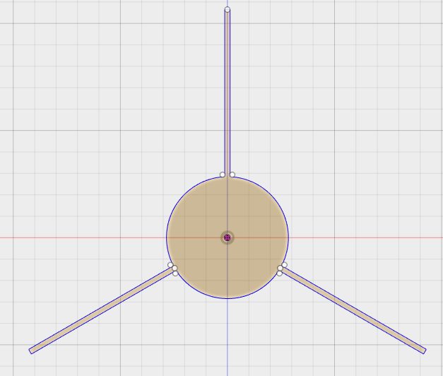
And cut two of them out from cardboard on my laser cutter:
6R2HonOl.jpg


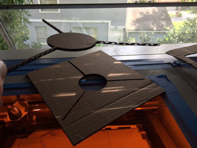
I covered the inside of each fin slot with a piece of blue painters tape, then slid the Pro54 case inside the body tube. I used JB weld to adhere each fin in place with the two guides:
xrKSq1wl.jpg


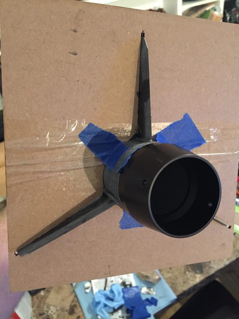
Once they were tacked well enough it was time for JB weld fillets:
O1gPegWl.jpg


These ended up being a tad small because JBW is a pain in the ass so I also covered them with some larger radius fillets made from rocketpoxy. Booster fincan done! The fins are very well adhered, I’ve put some weight on them and my calibrated elbow thinks they’re as strong as any TTW ones I’ve done.

Here is what I wanted to do that I didn’t end up doing:
I have a roll of flat copper speaker wire that I wanted to employ in this build for a couple of reasons including connector-less continuity between the avionics bay and the sustainer igniter and not having the ass-pain of fishing wires through tiny conduit. I did three separate test layups of this and came to the same conclusion every time: this stuff is too delicate for the corrosive, high-g environment of a rocket in the specific way I was going to try it. Other people have successfully used flat wire for staging but they seem to treat it always as removable and slip it past the motor casing, which I could easily do with this stuff. My objective was to make a wire setup that could be permanently installed in the airframe, and that is still within reach just not at the effort level I’m willing to give right now. The problem with permanently installed wires is that if they break for any reason your sustainer airframe is toast unless you’re willing to do some major surgery- a recommendation for avoiding that is to lightly file a very shallow slot in the airframe for the wire to sit, encase it with epoxy, and use some form of connector at each end which doesn’t subject the flat wire to friction or g-loads. This was more of a pain in the ass than I wanted, so I gave up and used the brake line conduit.
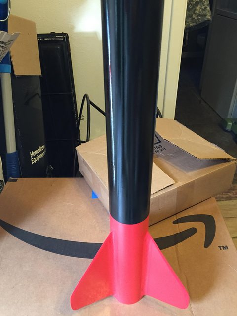
CpI5CySl.jpg

JZItRHSl.jpg


Here’s what I ended up with on the sustainer motor can:
6e4ndpxl.jpg


I bought the brake line on Amazon, cut it with a hack saw, and straightened it by hand easily. The sustainer retainer is a 38mm Slimline, which puts the entry to the conduit fairly far inside the sustainer can. I ran two strands of extra long, semi-permanent wire through there and I’ll just hook up the altimeter to one side and the igniter to the other each flight. If there are any problems I can use the existing wire to fish a new one through. Or I can just snake flat wire alongside the motor casing.

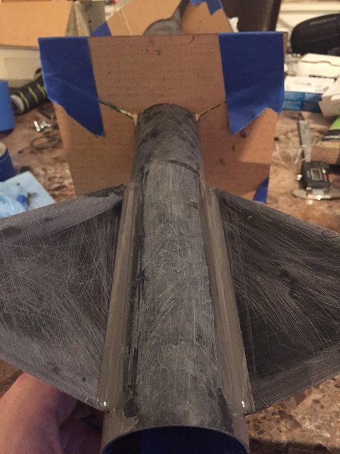
With that sorted I attached the sustainer fins using Hendrickson’s double-dip method. I ended up able to hear a creaking when I flex one of the fins in particular, and that method doesn’t inspire me with confidence about the CR to BT connection so I’m going to go back and inject some internal fillets this week.
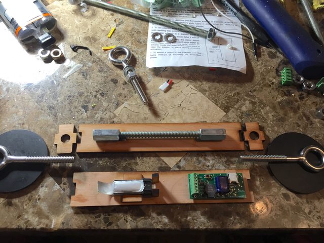
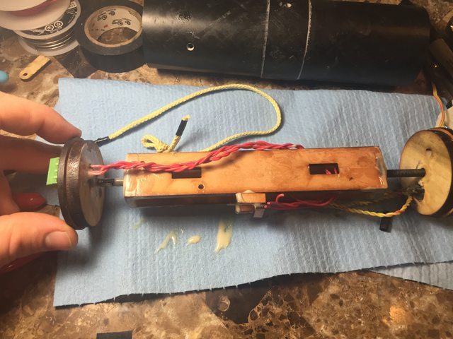
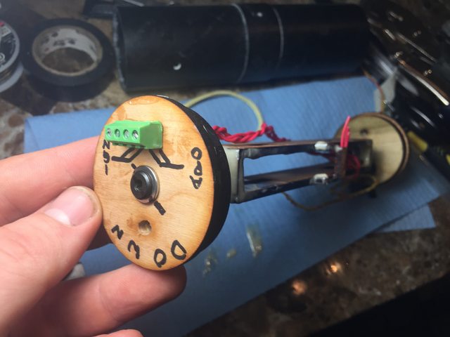
Building the interstage coupler on this thing has, despite the aforementioned excellent thread, been a confusing ordeal. I did mine in the recommended way, with a 38mm avbay tube inside of the 54mm coupler, sealed it all up in epoxy, etc. I shortened my avbay so that the 6GXL plus threaded forward coupler would fit, which still leaves almost no room for a chute in the booster. After fitting it together a bunch of times, I’m confused as to why the 38mm avbay is necessary at all; the remainder of the 54mm coupler, with a bulkhead glued inside of it, is more than sufficient to contain an altimeter/etc, and would leave much more chute room. This is how mine looks now, but I think I’ll end up building a second one to use with extra long motors that leaves off the 38mm tube since it’s pretty much just unnecessary weight and another wall which needs to be drilled through for vent holes. Another strategy for dealing with the extra long motor is simply increasing the length of the interstage vent band to two inches, which reduces one inch of coupler length inside the booster (there’s still plenty), or sliding another 1-2 inch vent band around the motor case before inserting it which essentially makes extra-thick thrust rings.

QW3MNtrl.jpg


Still has a long way to go, and I think I’ll be test-flying it on 1-3 grain motors for a while. :)

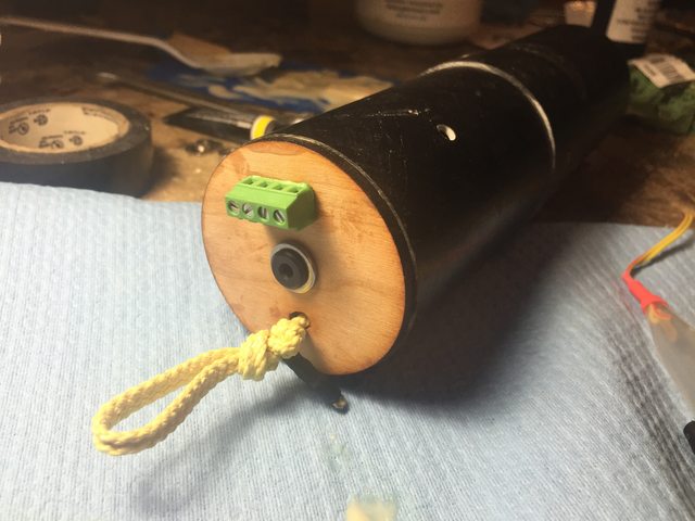
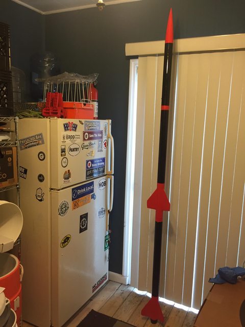
Here are the pieces assembled:
KT40LSyl.jpg


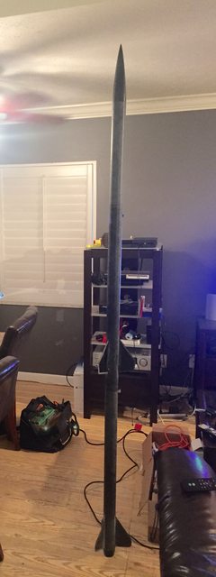
Too tall for the ceiling fan!
 
I did something similar to this.
The MD is a good option for this setup, giving more flexibility for booster motors.
Having the Wildman jr already I wanted something different.

I have flown the 2 stage stack twice but, without the MD booster.
On the first flight: the upper stage never lit... due to programming error.
The second flight was flawless.
It flew on an I 1299 to an I 345 to 5,595 ft

I did cut the 38 mm booster down 5" to make it look nicer.
I'm temped to add a third stage.


JD
 
Awesome, I'm glad someone else's worked so maybe mine will have a chance. :) What method did you use to mount the MD booster fins?
 
I used the existing slots and an alignment guides that I had.
The tabs were filleted over.

JD
 
Coolness. My Eggfinder arrived tonight and I soldered together the Tx module in about 2 hours while watching tv. I used a cheap Aoyue adjustable soldering station at the lowest setting with a pointy but not super fine tip. Easy build! Using a straight edge of masking tape to narrow the solder splash zone to one pad at a time was simple and effective.

DKRj8mal.jpg
 
Tonight's task was assembling the Egg Timer twofer I got with that 'Finder.

zpjxlLll.jpg


I assembled the first one somewhat hastily with the high voltage power regulator and hooked it up to a 9v aaaaaand nothing happened. I troubleshot it for another hour but all my solder joints looked good and I couldn't make it power on. I assumed I must've fried something, but as a hail mary I removed the voltage regulator and 9v jumpers and hooked it up to a 1 cell lipo. No change. This made me upset so I even more hastily built the second Egg Timer, hooked up the 1s and yet again nothing happened. Damn.

After an hour or so I came back to them and noticed that I had never hooked up any switches, and maybe I was following the letter of the assembly instructions too literally; I assumed I was going to put it in line with the battery but hey there are switch pads right there next to the battery ones. I jammed a resistor lead to short out the switch connector and wouldn't you know the altimeter came to life. Same result on the first one, now we're in business.

2 Stage Deployment Strategy:
So now I've got two Ravens and two Eggtimers. These new altimeters will go into other rockets so that I can use the Ravens in this two stage setup. I'm more comfortable with the featherweight air start and separation charge capability, plus there are no accelerometers on the eggs.

Booster: Raven for deployment control fires separation charge at motor burnout, ejection charge for chute burrito at apogee (no motor backup due to forward retention), cable cutter at set AGL ~700'. Booster carries RF-V16 cellular GPS since it's tiny.
Sustainer: Raven for ignition and deployment control. Motor igniter fires at booster burnout plus X seconds (specific to motor combination/sim results, probably 0 to start), streamer at apogee, main at ~700'. Nosecone carries Egg Finder.

My sims right now with an unrealistically light weight .rkt file are showing about ~7000 feet for an initial shakedown flight that's convenient to the motor hardware I have: a CTI I218 54mm in the booster to a CTI I800 Vmax 38mm in the sustainer. The booster should make it about 1700'. With separation at burnout and a 0 second coast the sustainer would hit about mach 0.95 at max which is pretty reasonable.
In the ridiculous category an L935 takes the booster to about 3500 and mach 1.4, and a 7s coast before igniting a J530 would send the sustainer to 21k at mach 1.8. But I am not yet super comfortable with OpenRocket so maybe I'm doin' something wrong.
 
Sustainer: Raven for ignition and deployment control. Motor igniter fires at booster burnout plus X seconds

A good way to use the Raven is to light the igniter at a predetermined altitude if T<X. Just as an example, say your simulation shows an altitude of 3000 feet at 6 seconds at the point where you want to light the igniter. You might program altitude > 3000 and T < 7 seconds with one burnout. Then, if you don't make 3000 feet in time (an off-angle flight or some other bad thing), the motor won't light. With 1 burnout and a delay, the rocket could be located/pointed literally anywhere when the sustainer lights.

Jim
 
Excellent point, thanks for sharing. I know those programming lessons are hard-earned sometimes so I'm happy to get the benefit of everyone's valuable experience. Since I haven't actually programmed the Raven for two stage ops yet my brain was thinking in the logic flow of Open Rocket's triggers which are a bit less flexible than the variables the altimeter has access to.
 
Congrats on your L2. I also built one of these Jr. two stage kits (dark star for me). I've only flown the full stack once (at LDRS) and it's easily my favorite flight to date. There's always that feeling of accomplishment when you fly a rocket, but when you get a sustainer to light and recover successfully, there is no other feeling like it IMO.

After that flight (two 38mm motor mounts) I decided to buy a new booster section from Wildman without the motor mount so I could make it MD. Just in case your curious on fin attachment method, I wrapped my 54 6XL case in wax paper and tacked to that, then did fillets and pulled the casing out.

The stock interstage coupler av-bay, in my opinion, is complete trash I guess you could say I'm lucky I destroyed mine so I have an excuse to rebuild it (I used a J530 IMAX as my sustainer motor, and at the time I didn't have a second altimeter for stage separation...). I'm going with a more conventional method for the interstage. I'm using a standard two layers of G10 for the bottom lid. The top lid will be a double layer of G10 coupler bulkhead resting about 3/16" under the bottom of my sustainer aeropack. I can post pics here once I have the materials to build it.

Unfortunately I think my 6XL casing is too long to use a booster motor (although it would be fun to try to fit everything), so I may limit myself to the 6 grain casing if I ever decide to buy one.
ImageUploadedByRocketry Forum1444309192.791806.jpg
ImageUploadedByRocketry Forum1444309232.470096.jpg
 
Thanks! I appreciate everyone's experience; the limitations of most search engines for short search strings make it difficult to find a lot of two stage (or 2 stage) info on a specific rocket. I've been away from town for this weekend and am looking forward to a productive rocket week before my local club's next launch.


I've got a 54mm I218 to 38mm I800 flight planned with motors inbound now, but before that I think I'll try a sustainer only flight to verify everything works. I've got an AT I205 hanging around in my rocket box that will lift the sustainer nicely to verify everything works. In another thread the EggTimer proprietor verified that I received a bad screen for my EggFinder kit so hopefully I"ll receive that part in time and be able to track the flight. When I do fly it two stage, I've determined that >500' at <3 seconds should confirm a relatively straight boost for sustainer ignition criteria on the I to I flight.

This week's plans require me to:
-drill vent holes in each flight section
-laser cut and mount my electronics sleds
-cut and knot my laundry lines
-mount both 36" parachutes I've got
-program my Ravens
-ground test the ejection charges
 
An easier way to search is to put this into your search bar:
site:rocketryforum.com "search terms"
 
Looking forward to hearing about the flights. The I800 is a wonderful motor for a lot of different things. Just be wary when you put it into a minimum diameter rocket. I want to put a couple I800s in my darkstar at some point. Think it would be an interesting flight. Maybe it will be the next flight, going to a launch in a couple weeks and I've been saving to fly this thing again.
 
Thanks for the input guys. Launch dates are always too far out, until two weeks before hand then they're way too close. This month is no exception as the local launch is this coming weekend and I still feel unprepared!

My EggFinder GPS tracker is unfortunately not operational yet; I've gotten some great help from cerving on the vendor forum so far so maybe it'll get going before the weekend but it's chewed up a ton of time without successfully transmitting yet; I know my RF-V16 tracker works great so I can always use that for the upper stage if nothing else.

I received my I-800 and I218 reloads from Wildman this week. As the build gets heavier and heavier the 54mm 1G motor becomes more and more marginal at guide departure speeds, so I may just buy a small J or an I455 VMax at the field instead to ensure I leave the rail with enough oomph. I've run a few extra sims and they will both keep it under 10000 feet.

I drilled injection holes in the sustainer fincan and injected Rocketpoxy with chopped carbon into the holes for internal fillets. I was worried about it flowing because of how thick and peanut buttery it is, but it worked just fine which makes me comfortable for future builds with that technique. One gotcha with the black fiberglass tubes is you can't see through them anymore, so I have no way of knowing how well it's actually covered the inside. I let each set lay up horizontally for about ten minutes, then put the tube nose-down to promote forward CR to BT adhesion.

For the sake of overcoming build paralysis I decided that this booster will be my "small motor" booster which only has the room for a Pro-54 6G and not the 6XL. That extra room gives a lot more space for the coupler and the chute. I taped off my XL case at the length of a 6G motor and stuck it in, then used that as the guide for tacking my recovery harness against the side of the BT:

dFFpTIVlt.jpg


I sanded the inside of the tube with some sandpaper wrapped around a hammer handle. While the syringe was still full of epoxy I taped it to the end of a couple of popsicle sticks to reach inside the tube then used another to depress the plunger:

cYyT1f6lt.jpg


Voila! A small, low-profile, very strong anchor point:

27fzTGOlt.jpg


Now I've got exactly the right amount of room for the interstage, a 36" chute, and a 6G case. If my electronics issues aren't sorted in the next day or two then I'll just make my goal to test fly the sustainer on one of the motors I've got kicking around the house. I also ordered and received a cheap keychain camera (https://www.amazon.com/gp/product/B00GN6S7PA/?tag=skimlinks_replacement-20) which will eventually be taped to the outside of the rocket so I can film and review the separation and sustainer ignition events.

[edit] This section was changed to an Aeropack, suckas!
 
Last edited by a moderator:
Looks like it's coming along great so far.

As far as tracking goes, when I flew my darkstar, I only had a comspec radio tracker in my sustainer. When the sustainer did light, it was at a slight angle and landed over a mile away on some hilly terrain. Tracking was a nightmare, but it was recovered from its 11,000' flight.

Good luck with yours, two stage rockets are easily the coolest and most complex flights out there.
 
All you did was epoxy your Kevlar to the side of the tube?

Not sure how strong that will be.
 
All you did was epoxy your Kevlar to the side of the tube?

Not sure how strong that will be.

Encasing a length of the recovery harness material against a MMT is a common practice, and is in the instructions for most of the wildman kits. This is essentially the same thing, but since it's MD there is no MMT to attach to. I've used the same method to attach a recovery loop to the inside of other rockets (it's even in the instructions for large diameter LOC kits) and the bond is plenty strong as long as the surface was prepped and sufficient adhesive is used. A swing test in the yard or weight hanging test will confirm that it stands up to normal deployment forces without issue, but if you've seen evidence of this method failing when used as above I'd love to be educated so that I can make adjustments.
 
Ah I can't believe I missed the shock cord attachment. Along with my earlier post about the stock interstage being trash, the recommended shock cord attachment method is also trash. If your shock cord gets burnt out (due to ejection charges) and snaps, then your SOL.

What I've been doing recently (and will be doing for all rockets I can do this for) is attaching the shock cord directly to the top of the motor. I don't use motor deploy anyway. This method allows me to remove and replace the shock cord as necessary. I use the aeropack CTI adapter for their line of minimum diameter retainers to accomplish this.
 
Encasing a length of the recovery harness material against a MMT is a common practice, and is in the instructions for most of the wildman kits.

Agreed. The main difference there is that it's typically a very long length, say 6-10", and often 1" strap which has a lot more surface area. The other difference is that the cord is further trapped where it passes under the CR and is encapsulated in a fillet there.


This is essentially the same thing, but since it's MD there is no MMT to attach to. I've used the same method to attach a recovery loop to the inside of other rockets (it's even in the instructions for large diameter LOC kits) and the bond is plenty strong as long as the surface was prepped and sufficient adhesive is used.

LOC kits do use this method, that's true. There's no risk of a bad bond on the inside of a paper tube due to the fact that the paper is porous. The paper tubes and wood fins don't weigh a lot which means the mount doesn't need to be overly strong to withstand even a slightly more energetic than planned ejection event.

A swing test in the yard or weight hanging test will confirm that it stands up to normal deployment forces without issue, but if you've seen evidence of this method failing when used as above I'd love to be educated so that I can make adjustments.

A swing or hanging test is an ideal situation with even loading, no shock, etc. What you want to do is a drop test with your motor case installed or somehow replicate the mass of your interstage hitting the end of the cord at the same time as the booster. This method very well may work, but it may not be sufficient for anything much beyond an ideal deployment scenario. Those Pro54 cases are heavy!
 
Those are all great points. I don't have an aeropack MD retainer but can look to one in the future and it would be easy to slip a notched CR in front of this cord attachment to make another anchor point. Extending the glue area is also easily done.

For what it's worth, I think a proper epoxy bond in this method is sufficient within a reasonable window on either side of ideal deployment. I described it poorly with "weight hanging", but to test this I put a 6GXL case inside the booster tube, then duct taped an 8 lb tool bag to the fin can creating a shock mass over five times what the normal burnout weight with the largest case would be. I attached the anchor point to a shock line hanging over my second floor railing and gave it about ten sharp impact drops without any noticeable effect on the setup.

This is not a perfect test, of course, because it only has 8 feet or so to accelerate. I could anchor the fincan in my truck bed and deploy the chute at the "just below shred" speed to test it, but that's kind of unnecessary since it's outside of the intended window of normal operation. My due diligence is to note my drogue/streamer (I can fit both, haven't decided) descent rate versus main descent rate at maximum burnout weight and perform a shock load test at the limit of that force if it exceeds what I've already done. A way too early or late event, a shock cord that's too short, or a deployment charge that's too big are reasonably accounted for by ground testing and electronics programming.
 
Last edited:
In the interest of preventing failure, I'll add that I think this is not the best way to attach an anchor in an MD. Don't forget epoxy softens as it gets warm.

I'd get it wedged in/around a coupler and mount that as a hard point.

Where you are now? I'd scuff the snot out of the inside of that tube, and drop a layer of glass over those cords
 
No worries guys, I'll throw a CR in front of it to provide an additional means of attachment. But I'm extremely tempted to bond a kevlar loop to a fiberglass tube, tie it to a long rope that goes over a 15' branch in my yard and anchor it to something heavy, then pull and drop it with increasing amounts of weight.

In other build news, today I received the spare coupler I ordered so I can ditch the 38mm inside 54mm weirdo avionics bay setup. I measured everything out, bonded the airframe band at the right place, and notched the booster and sustainer so I could make epoxy keys on either side of the coupler band. One two stage consideration I've been worried about is interstage shifting: I've got it well butted against the sustainer aft CR to prevent axial shifting, and with the two keys it won't be able to rotate either. This will help ensure that I've got consistent friction for separation events. Also got my sustainer raven programmed today, and the shipping notice for another component that needs to be replaced on my eggfinder.
 
No worries guys, I'll throw a CR in front of it to provide an additional means of attachment. But I'm extremely tempted to bond a kevlar loop to a fiberglass tube, tie it to a long rope that goes over a 15' branch in my yard and anchor it to something heavy, then pull and drop it with increasing amounts of weight.

I would recommend you bond more of the cord closer to the end of the tube. Increase your bond surface area and you increase your strength. You don't want to stress the bond too much in "testing" as it can compromise the strength for flight situations.
 
Agreed. The main difference there is that it's typically a very long length, say 6-10", and often 1" strap which has a lot more surface area. The other difference is that the cord is further trapped where it passes under the CR and is encapsulated in a fillet there.

While I used full inch strap, my latest rocket probably only had three or four inches length glued down. It works great. I do not imagine the centering ring fillet helps much, but I could be wrong. All this being said, I am not entirely happy with the straps glued to motor mount technique. It has served me well and I have yet to encounter a real problem, but something about it feels goofy. I keep thinking all our rockets would benefit from a more positive and professional means of attaching parts inside the round tubes.

smapdiage9 said:
Hello, I am a recently minted L2 who has not yet flown any K or L motors and has also not yet acknowledged the severe cost of propellant in my new impulse range. Given that oversight, I decided to build my first high power two-stager: a Wildman Jr. kit I picked up this summer. And since I happen to have a Pro54 6GXL case kicking around the house

Hah, if you are concerned about cost, 54mm6XL is probably your single worst size! They sure are fun, though.
 
Not concerned, just naive. :)

I put this one aside for the last launch since there was no way it'd be ready in time, but it was a good opportunity to break mach in my Wild Child with an I-205.

Anyways, I've been playing with avionics bay designs for the sustainer. The WM Jr comes with no sled, two aluminum bulkheads, and two 1/4" welded eye bolts. I've always found avionics bay design the most annoying part of a rocket to implement elegantly, and I've never been fully satisfied with one I've made but each attempt gets me a little closer.

I don't like these parts for a couple reasons:

IVmuMIll.jpg


Two bulkheads, the two eye bolts, and a coupled allthread section weigh a quarter pound by themselves. This could be reduced with smaller, aluminum hardware of course, but those aren't the stock parts. This design is prone to being unscrewed during rotation in the descent, which requires extra considerations that are annoying to implement. Additionally, though I do have a small mill, working aluminum is just messy and irritating. Even if I replaced the eye bolts with kevlar loops, I'm still over 80 grams just to keep the thing coupled with a single allthread rod:

BxUcmb9l.jpg


My original design with these parts was to create a double sided, boxed sled around the connecting hardware:


In order to come up with a new design I had a couple requirements
1) the chute opening load path should be through the coupler tube and never through the sled or its connecting hardware,
2) the bulk plates and sled must be secured in place sufficiently to align the internal screw switch with a vent hole,
3) whatever secures the components inside the coupler tube should not be directly connected to whatever secures the assembly to the shock cord, in order to prevent unscrewing.

Most of my flights recently have used knots instead of quicklinks, and this plus my experience tying rappelling lines gives me a lot of confidence in that technique and the strength of these materials when used within their designed limits. So that makes some easy weight savings, and since the rest of the harness can be no stronger than its weakest section of kevlar strap I see no reason why a length of kevlar, running through the avionics bay, with stopper knots and double figure eight loops at each end is any less suitable for service than the standard bunch of steel parts. Here's my working prototype to meet those design requirements:

jI0b6Tgl.jpg


For efficiency's sake I re-used my boxed altimeter sled, but more space could be realized with another design. Instead of sending hardware through the center of the sled, I epoxied two tee nuts into each end to receive 40mm M6 bolts that would allow me to secure the bulkheads in place. For ease of assembly, one side is glued in place. An offset hole in either bulkhead allows that knotted kevlar strap to run through and create attachment loops on either side. When assembled, the sled hardware supports only the weight of the sled and electronics, through the center of the bulkplate and into the coupler tube. Deployment loads are supported by the kevlar, pulling against the opposite side bulkhead and through the coupler tube. The kevlar strap travels through a loose loop fixed to the sled, so even in a complete dual bulkhead failure the electronics would still have a chance at remaining attached to the harness. A notch/key on the fixed bulkhead side serves to align the screw switch with a port on the switchband.

I soldered some interior wires to through-bulkhead screw terminals to ease assembly:

0A7zxZFl.jpg


Assembled with some quick overhand loops for test purposes:

BG5uPESl.jpg


3aZ3LH8l.jpg


All the hardware, both bulkheads, the sled, a slightly shorter kevlar strap, and epoxy for 58 grams. I think that's okay for a first prototype. This one is built pretty sloppily, and once I get ground testing done I may decide to refine it, probably starting with just making the sled longer and gluing it directly to the fixed side in order to lose half the hardware and free up more space for stuff.

I forgot to include the other important part of the discussion: optimum mass. As I was sorting through the stock open rocket file for the Jr. 2 stage and comparing it to my actual data a few oddities popped up. Most notably that my booster tube is three inches shorter than the file indicated it should be, and my sustainer fincan ended up kind of heavy at around 620g after injecting epoxy and adding a slimline retainer. For a maximum performance flight, I'd be designing to the optimum mass of the intended motors. Since my local waivers will not even support half of what that profile would be with this rocket, I'm more concerned with being light enough to keep good launch speeds on big I/small J boosts. Beefier, heavier components are easily swapped out whenever I make it to a 6 grain-worthy field. :)
 
Last edited:
Nice! I love getting creative with avbays, nice to see where you are going with this one. I have also used the kevlar line in place of more threaded rod. Be aware of the potential for slack that would snap upon deployment. I cannot see the bottom of bulkheads in those last pictures but you may have accounted for that.
 
I've had the same concern because it's tough to tie a stopping knot against the bulkhead without slack. Solutions I've considered include fastening a bracket against the bulkhead that fixes the kevlar, but that's annoying, tying an overhand knot below my figure eight and just sliding it down, but that's reducing the strength of the cord, and finally using an add-on material to take up the slack between the bulkhead and loop such as several wraps of masking tape. That's what I'm leaning toward, since it will serve to decelerate the slack shock even if it gets ripped off. Probably going to use some kind of non-wicking, removable substance like hot glue or silicon sealant to close up the holes before each flight, which will also help fix it in place.

Last night I had a wiring revelation that I've never seen anyone talk about before: what happens at apogee if your sustainer igniter wires are shorter than your recovery harness? Well they've gotta get ripped out of somewhere, and putting new ones in is enough of a pain in the butt that I don't want to do that. I soldered a jst connector on the upper side of my igniter wires so that I can run the opposite jst connector off the bulkhead and create a pull-apart connection that's good enough to withstand the acceleration of boost.

mkJgP3pl.jpg


Right now the wires are taped to the harness and the inside of the booster tube as strain relief, there are more positive ways to do it but it seems to work great as is. In an ideal world I could put another jst connector down by motor so that the actual airframe wires would never be chewed up in flight.
 
Last night I had a wiring revelation that I've never seen anyone talk about before: what happens at apogee if your sustainer igniter wires are shorter than your recovery harness? Well they've gotta get ripped out of somewhere, and putting new ones in is enough of a pain in the butt that I don't want to do that. I soldered a jst connector on the upper side of my igniter wires so that I can run the opposite jst connector off the bulkhead and create a pull-apart connection that's good enough to withstand the acceleration of boost.

I honestly can't remember how I did mine. I think I had the wires twisted together the e-taped. What I can remember was that it worked.

I like your idea a lot better. Let us know how that works as you'll probably be flying this two stage before I get mine up again.
 
Revisiting this build since the last update. :cool:

As plans often do mine have changed repeatedly and this rocket has yet to fly despite being mostly ready!

I keep getting distracted by other stuff:

First, I had to hack off an 18" section of the fincan from my Vertical Assault due to a truck-induced zipper and replace it with a different-diameter FWFG tube and coupler. This went pretty smoothly, and she flew again on a J360. This was also the first flight of my Eggtimer TRS, which was spectacular to use with altitude readings in flight and charge fired indications on the ground. This was also the first flight of the $40 noname HD keychain camera I got from amazon, held in place with gaffer tape. Everything worked great:

QrFs7fel.jpg

https://www.youtube.com/watch?v=wmpaTOxjzZo&feature=youtu.be


Second, I thought about the mistakes I've made along this build and decided to give the whole idea another go with something that's been sitting on my kit pile forever: a PML Mini-BBX with Terrier booster. Using the lessons learned in this thread, I was easily able to modify it for normal (non-CPR setup) dual deploy, a sustainer motor fired from the sustainer avionics bay via conduit tube, avoid notching the interstage coupler, and make room for a real separation charge. Essentially it was a low performance, old-school do-over of what I've done here. Rocket went together in two days and is now ready for paint, and since it will fly on the same electronics used for this I might just put it up for some two stage HPR action in the 3-5k range instead of scraping 10k first.


Here's what I've done:

Revisited my MD retention for the booster. At the time of this build, I'd only built one HPR this year (a Wild Child) and none in the five years before that due to some inactivity so this project has taken me down many research rabbit holes and put the glow back into a few old mental lightbulbs. I decided that with the amount of booster tube I was working with stock, it simply wasn't going to work to adequately retain a 54mm 6GXL motor entirely within the tube. Since my local field doesn't come close to supporting a flight like that anyways, I tuned the goals for this booster down to more like a 4-5G length of motor tube which gives me plenty of room to install an Aeropack MD retaining bulkhead. A short sleeve of body tube to act as an extended thrust ring could afford more space, but at the high forces involved in a max performance flight I'd rather have a different interstage setup anyways so I might as well consider this my "below 10k" booster and just build another one for giant motors when the time comes.

I ended up fixing the MD retainer in place with epoxy per the instructions. Before I did that I attempted to fabricate a removable retainer using captive pem nuts inside a coupler tube like a few other people on the forum have done. That part went fine, but when I attempted to make countersunk holes on this 54mm tube for the first time I realized quickly that my skills need more practice. The hardware I had on hand was very stout but probably a little too big to comfortably countersink in this tube size, and when I drilled the holes my countersinking bit chewed the hell out of the wound fiberglass leaving a non-round, way bigger hole than necessary. Discouraged, I took the commercial solution in red anodized aluminum and glued it in place, sealing up the hole with epoxy. I'll investigate this further for next time.


mBoOjfyl.jpg


I completed the NC ebay for my eggfinder and lipo. The sled has tabs going through both bulkheads, and a loop of kevlar goes through the bulkheads and sled and ties on the harness side. This is a pretty routine design that I've used with laser cut bulkheads and sled at the end of the recovery harness, and the assembly screwed into coupler nuts that have been epoxied/glassed to the inside of the nose cone. I do this on lots of rockets and it's held through every deployment and up to a 40G launch without complaint, but I do find the heavy hardware and surface adhesion to be kind of inelegant and will probably move to an epoxied-in centering ring with T nuts on larger nose cones.

GHJHblbl.jpg


Shot a simple paint job with the help of my assistant Bandit. Rustoleum 2x rattle cans, white primer, a satin flourescent-ish red for fins, cones, and bands, and black for the rest of it. Here he is helping:

Evj9G5sl.jpg


DSo8z3Bl.jpg


VKyvOaEl.jpg


Something I've started doing since a terrible tree recovery a few months ago was writing my number and email on my fins. If the thing stays in a tree for longer than I can hang out, at least I'll have a small chance at someone returning it later.

Finally I've completed ejection charge ground testing on the entire rocket. The body tube sections in the sustainer each worked great at about 1g. The recovery space in the booster is MUCH smaller and was quite energetic with 0.6g, and the separation charge was also very snappy with 0.3g.

I took the whole stack to the Tripoli Tampa launch a few weeks ago with the intention of at least flying the sustainer for a shakedown. For its first two-stage I've got an I455 (54mm) and an I800 (38mm) on hand to kick the thing off the pad depending on final launch weight; the trouble with not owning all the world's motor hardware is finding a 1G case to borrow versus flying my 3G plus two spacers. Either option requires a Rube Goldberg-ian assembly of allthread and motor adapters to reach way up into the fixed MD retainer. This is another place where having a screw-in, removable retainer is awesome because you could just drill a second set of holes lower in the booster. I'll get it right next time. :)

In my rush to pack for the November launch I forgot my fly-away rail guides. I took it as a sign to wait for the next launch on the Junior, and it'll be even more ready then.
 
Finally I've completed ejection charge ground testing on the entire rocket. The body tube sections in the sustainer each worked great at about 1g. The recovery space in the booster is MUCH smaller and was quite energetic with 0.6g, and the separation charge was also very snappy with 0.3g.
Wow I really must be doing something wrong on my ejection charge tests. I'm using 1.5 grams on my 3" diameter 2 stage for the interstage coupler separation :p
 
At 0.3g my sustainer landsharked across the lawn pretty quickly! I have very little volume on the upper side of the interstage, and tested it with a motor installed and taped over so there was really nowhere for the gasses to go. At 1.5g I think I would've entered the neighbor's yard!
 
Back
Top