Eggfinder and LCD Receiver Build Thread

The Rocketry Forum

Help Support The Rocketry Forum:

This site may earn a commission from merchant affiliate links, including eBay, Amazon, and others.
Oh, you've never seen the antennas I've had to lug around in the past. A full wave in 900mhz is less than a foot and a half. Tiny thing.
Much easier than a solo-lift on an OE-254! I'm not so worried about free-air reception, more about keeping hold of weak signal after landing.
The Linx are only advertising under 2dbi reception. I'd like 5dbi or higher, without going directional if I can avoid it.

I'll probably grab the Linx for convenience, as I need to get a build finished soon and need to watch the budget. I also have to place an order with Mouser this weekend too.
But this is more along the lines of what I'll be grabbing for next season.
https://www.l-com.com/wireless-antenna-900-mhz-5dbi-rubber-duck-antenna-rigid-rp-sma-plug-connector#

I did finish up the Eggfinder itself last night, but I have a blazing headache right now. So I want to get away from the computer for now. Is there a setting to turn off the beeping on the receiver?

-Hans

I put like 4-5 layers of electrical tape on top of the piezo to make it bearable.
 
That beeping has got me in trouble a couple of times with the safety guys out at the launch pads. They think I'm carrying a live altimeter around in my rocket before it's on the rail. I won't carry the LCD Rx around anymore, it stays in the truck. I can mute the beeper when running "Rocket Locator" on my android, and I have a more portable RX with a bluetooth module linked to it.
Now if you really want the slick setup, you need to talk Kyle G. (BLKKROW) into making one of his custom housings for the LCD Rx.
 
Last edited:
Ok, now I give the bench a good cleaning again (Amazing how fast things clutter up sometimes), and lay out the Eggfinder itself for inventory.
Again, go by the current inventory list, as things are going to change. For instance.... now it's a pair of 10uf electrolytic capacitors included, instead of a 10uf and 47uf due to a change in the voltage regulator. Everything is here. Smaller part count than before. But don't let that deceive you.

eggfinder-047.JPG


Meet your nemesis. Your dark cloud. Your greatest hour.

Your GPS module.

eggfinder-048.JPG


A word on soldering tips here, and please take this completely as the tongue-in-cheek humor that it's meant to be.

Look close at your soldering tip. Think it's sharp? Jab yourself lightly in the palm. If you didn't draw blood, you need a finer point.
I am kidding about stabbing yourself, but not kidding about how fine a point you'll need here. If you have a crap generic soldering iron, you're going to struggle.
I know I did, and I have a good iron, but not as fine a point as I should have.
 
This step took me about 20 minutes to get right. I taped the PCB down to my bench, then lined up and taped the GPS module down to the PCB. It's a much finer pitch than the RF module, so you're going to struggle here. If you have magnification available, use it. This GPS module is the hardest part of this build, by a long shot. It may even make you sweat and get all cranky around your family.

If you've never done something this fine pitch before, and it takes you less than an hour, you've rushed it. I can't stress enough that the Eggfinder instructions are very good, and will steer you right. Follow them.

eggfinder-049.JPG


Some good suggestions for magnification are a Donegan Optivisor or Carson Magnivisor.
https://www.amazon.com/dp/B007CDJKM2/?tag=skimlinks_replacement-20

Also consider a bench mounted magnifier. Get one with built in lamps.
https://www.amazon.com/dp/B0011X2GN4/?tag=skimlinks_replacement-20

https://www.amazon.com/dp/B0021GIV7U/?tag=skimlinks_replacement-20

Decent hobby magnification is cheaper and more accessible than it used to be. There's no excuse anymore to settle for crap.
 
Last edited by a moderator:
Do some yoga, maybe a bit of meditation. Find a happy place. Make sure you're calm and not shaky.

Then solder that first pin. Scrutinize it. Check ALL the notches to make sure they're still lined up. Correct if needed.
This one needed a bit of cleaning but was otherwise ok.

eggfinder-050.JPG


Feeling good? Wait a minute to get back into the zone. Then do pin #2

eggfinder-053.JPG
 
Sweating yet? No? Good. Take a breather, then spin around and do the two corner pins on the other side.
Give it a minute between pins

eggfinder-054.JPG


Then over the next half hour or so, taking breaks as needed. you can get the rest on the top side.

eggfinder-051.JPG

eggfinder-052.JPG


Feeling good? It's not over yet!!!!! Don't get all cocky here. You still have to do the back side.
Again, take your time. Give it 30-60 seconds between pads. Follow the instructions about skipping around, like you do when torquing things down.

eggfinder-055.JPG


Take another break, until you stop freaking out, then come back and inspect it all very carefully.
This was by far the hardest part of the Eggfinder assembly. If you're looking good here then it's all a nice cruise until the end.
 
Last edited:
Next we'll do a new one, the Atmel processor. If you did this as the first part you soldered, it would seem difficult. After that GPS, we're on easy street.

(After I assembled mine, a great thread about an optional method popped up, which gives an auto-start ability.
https://www.rocketryforum.com/showthread.php?128415-Eggfinder-Auto-start
Worth checking out )

eggfinder-056.JPG


Another case where taping the PCB to the table made things easier. I tinned one pad, held the part with tweezers, and soldered it down.
As always, make sure it's still in place before proceeding.

eggfinder-057.JPG


Then all 4 corners

eggfinder-058.JPG


And the middle pins to finish it up.

eggfinder-059.JPG
 
Another voltage regulator, with little comment. You've already done two of these, so it seems easy now.
Funny thing about macro photos, you start seeing things that you missed via the naked eye, even with magnifcation.
Looks like I missed a pin on my GPS unit, which leads to the 'Ready' LED. I was wondering why that LED wasn't working

eggfinder-060.JPG


Then two more old friends. A .1uf capacitor, which still isn't polarized. Thru-hole stuff is a piece of cake now, ain't it?
Plus another RF module. Same module as last time, but for some reason this one installs faster.

eggfinder-061.JPG


And a pushbutton. A simple thru-hole part, no polarity to be concerned with.
Sorry about the dark photos on the last two. Was trying some different lighting and it didn't work out the way I wanted.

eggfinder-062.JPG
 
Now some nice and easy thru-hole stuff to finish it all up. Little commentary on these as at this point the soldering has been well explained, and they should go pretty easy.
LED's may come either clear or colored. Should be labeled if there's any confusion. Mine were easy to sort out.

Green 'Ready' LED, the longer of the two legs goes into the + hole.

eggfinder-063.JPG


Red 'Power' LED. Same deal on the polarity.

eggfinder-064.JPG


Amber '1S' LED. Same deal on polarity.

eggfinder-065.JPG
 
Now on to some resistors. First will be the 330 ohm resistor. This is mounted vertically, as you can see. Polarity doesn't matter, and which hole the resistor goes over doesn't really matter either. It's a matter of preference, but I went this way to give better clearance between resistors. This is the Orange Orange Brown resistor

eggfinder-068.JPG


Then four of the 2.2k ohm resistors. These are red-red-red

eggfinder-066.JPG


Then a pair of 10k ohm resistors.

eggfinder-069.JPG
 
Last edited:
Last two parts, the electrolytic capacitors. Polarity matters on these, so watch the light colored stripe, which indicates the negative side.
Newer eggfinders have a pair of 10uf capacitors due to a change in the voltage regulator. So you're fine putting one of these where it's marked for a 47uf.
Older units may have a 47uf and 10uf, so watch out on your packing lists and check the values actually marked on them.

eggfinder-070.JPG


Lastly, the antenna. Installs the same as the one on the LCD receiver. Again, I've built mine with the wire antenna to show it. I'll change it over to the RP-SMA connector later.

eggfinder-067.JPG


Next we'll move on to power and operation.
 
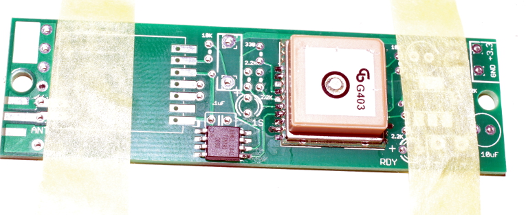
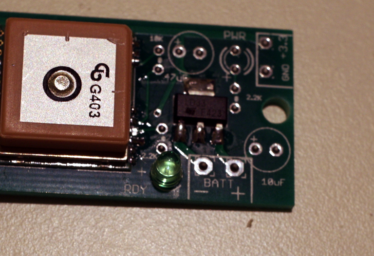
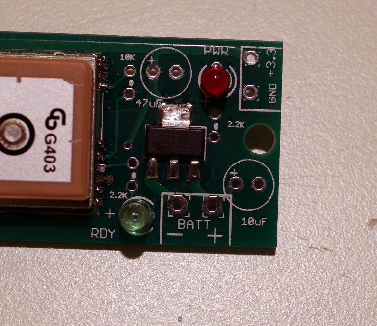
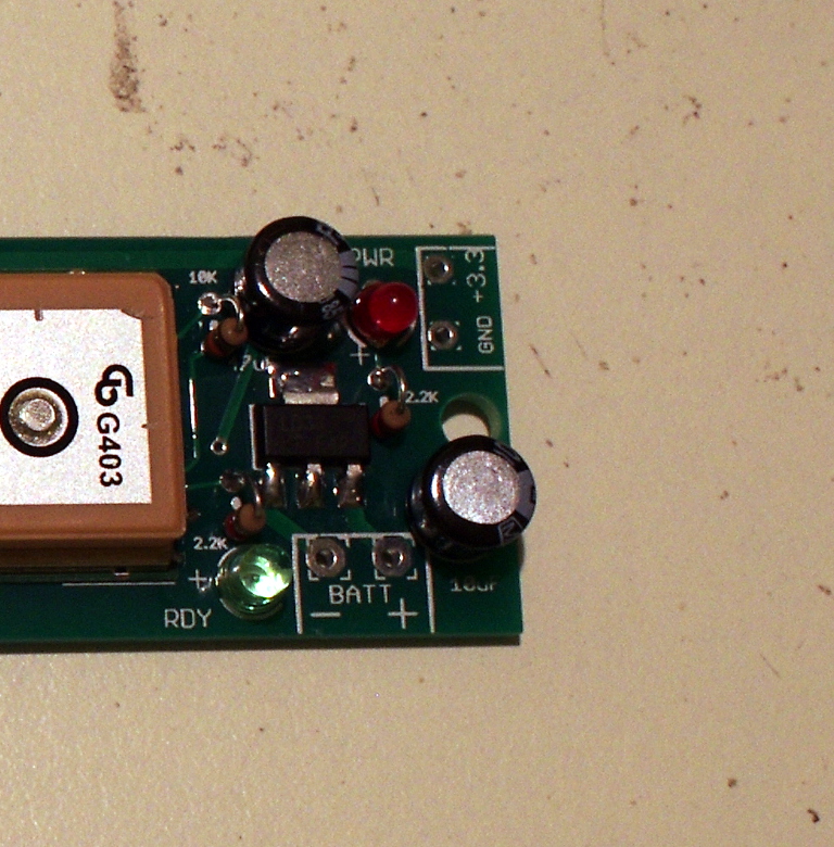
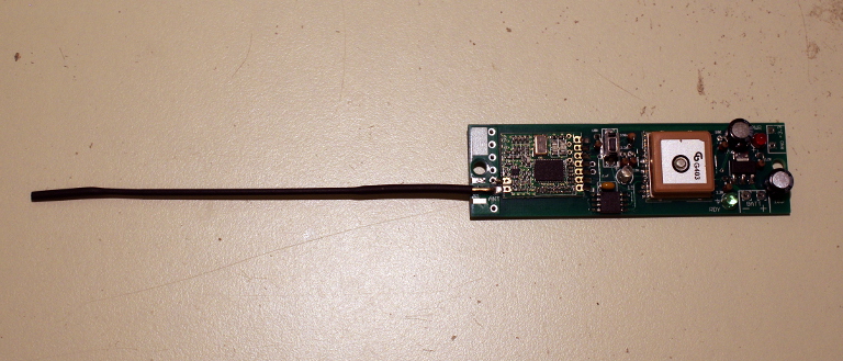
Power is up to you. It's advertised as a pretty wide voltage input range, for the purpose of testing here I'll be using a generic 9V battery. Eventually I'll be moving to a LiPo battery. I'm waiting on some connectors in the mail. It's important that you use the correct power input. Use the one marked 'BATT' as it's before the regulator, and will correct any voltage issues before getting to the active components. Do NOT use the one marked 3.3v, as that's a regulated OUTPUT for advanced users. Put too much voltage into the 3.3v holes, and you've just fried both the RF and GPS units.

eggfinder-072.JPG


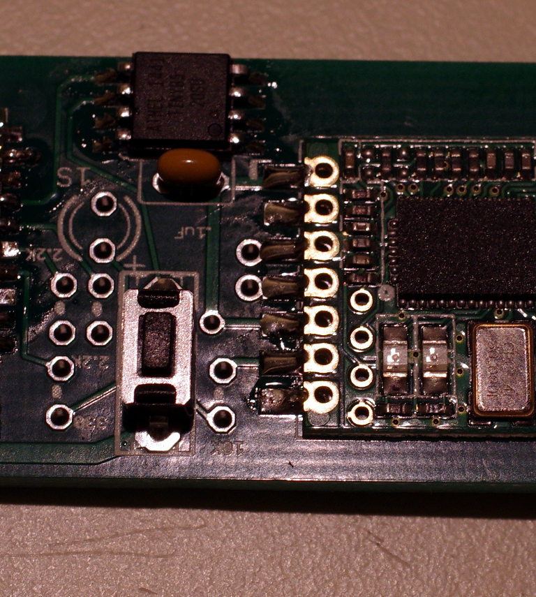
Operation couldn't be easier. Plug in the battery to the eggfinder, and watch your RF unit. If you see a green flashing light, that's actually a bad thing. It means somebody is already using that frequency and you don't want to proceed any further until sorting that out. If you just get a quick flash of both RF lights, and a steady red power light, you're good to continue. Hold down the pushbutton for a second, then release, and the green 'READY' light will come on. You'll also see the red light on the RF unit blinking every second or so.

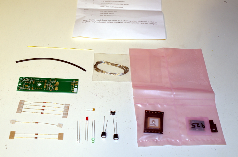
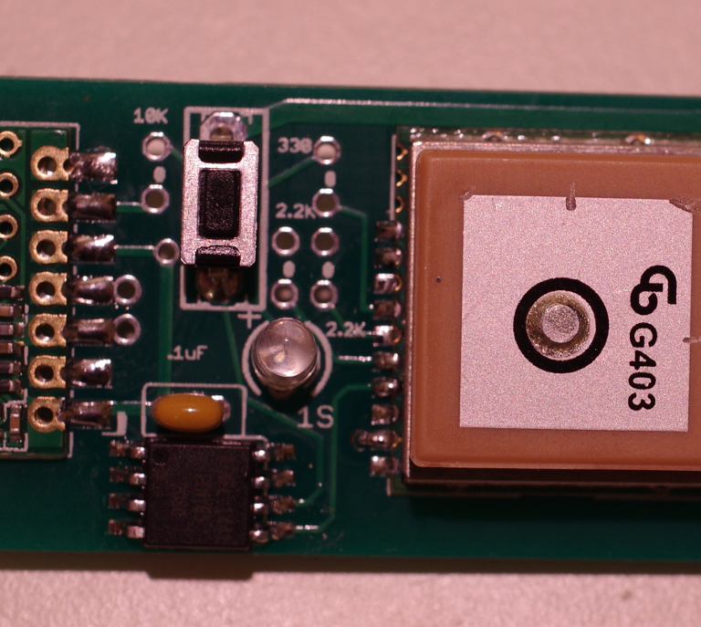
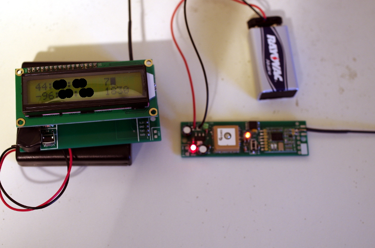
First time you use it though you'll probably have to set your frequency in the receiver. The Eggfinder LCD receiver instructions explain it better than I can. The frequency of your eggfinder is printed on the outside of the package, plus would also be written on the pink baggie the GPS unit was in. Mine is 925. But if the frequency is already set, then just turn on the receiver and wait a bit. You should see a green blinking light on the RF unit of the receiver, which blinks in sequence with the red light on the transmitter. This means you have good reception between the two. Now you just need to wait for the GPS fix.

Might take a few minutes, particularly indoors. GPS can be slow to link enough satellites sometimes. Once you do get a fix, the receiver will start chirping every second, and will display the coordinates of the transmitter. Top right is your # of satellites. If that hits 5 or more, the orange light on the transmitter should also be blinking every second or so. The box next to the # of satellites is the quality of the fix. The more filled in the box, the better. Bottom left number is your altitude. Remember this is measured ASL (Above Sea Level) not AGL (Above Ground Level), so unless you're near the beach it should be well above zero. For instance, where I live is about 1830 feet ASL. I have a good fix on 7 satellites, and I had to blank out the coordinates because it really was tagged right at my workshop at home.

eggfinder-071.JPG


That's it for the time being. I'll work on the LCD case later, same with antenna updates, and mounting.
 
Oh, you've never seen the antennas I've had to lug around in the past. A full wave in 900mhz is less than a foot and a half. Tiny thing.
Much easier than a solo-lift on an OE-254! I'm not so worried about free-air reception, more about keeping hold of weak signal after landing.
The Linx are only advertising under 2dbi reception. I'd like 5dbi or higher, without going directional if I can avoid it.

I'll probably grab the Linx for convenience, as I need to get a build finished soon and need to watch the budget. I also have to place an order with Mouser this weekend too.
But this is more along the lines of what I'll be grabbing for next season.
https://www.l-com.com/wireless-antenna-900-mhz-5dbi-rubber-duck-antenna-rigid-rp-sma-plug-connector#

I did finish up the Eggfinder itself last night, but I have a blazing headache right now. So I want to get away from the computer for now. Is there a setting to turn off the beeping on the receiver?

-Hans

The short antenna has been proven to be very effective at higher altitudes then the far great majority of flights....
The antenna is what takes the worst abuse traveling in my truck,, the longer the worse it is...
The longer antenna is to keep the signal for a longer time when it's being attenuated by earth after landing.........

When you're "fox hunting" an RF signal you need it after landing .....
The whole point to GPS is you don't need the signal anymore after landing...
The last packets you received was just before landing....
Create a waypoint with that last packets coordinates and go to it,,,
the rocket will literally be within a few feet of where you're directed to go.....

I would not recommend a different antenna at all....
I'd stick with the set up the manufacturer recommends...
After all,, he's done the most work with this unit,, he designed it...

Teddy
 
Linx antennas are good to 25K! And like Wayne said, get a 3D printed case from Kyle G.

20150829_201151.jpg
 
Last edited:
The short antenna has been proven to be very effective at higher altitudes then the far great majority of flights....
The antenna is what takes the worst abuse traveling in my truck,, the longer the worse it is...
The longer antenna is to keep the signal for a longer time when it's being attenuated by earth after landing.........

When you're "fox hunting" an RF signal you need it after landing .....
The whole point to GPS is you don't need the signal anymore after landing...
The last packets you received was just before landing....
Create a waypoint with that last packets coordinates and go to it,,,
the rocket will literally be within a few feet of where you're directed to go.....

I would not recommend a different antenna at all....
I'd stick with the set up the manufacturer recommends...
After all,, he's done the most work with this unit,, he designed it...

Teddy

Honestly, I really just like to tinker. I'm the kinda guy who's always looking for a better way..... even if the current methods are very good.
 
Honestly, I really just like to tinker. I'm the kinda guy who's always looking for a better way..... even if the current methods are very good.

Maybe you should try tinkering with a rocket that could test the range of the current antenna. My highest flight is currently 23,230 ft. with good signal regained before apogee, lost during boost. I use the stubby rubber duckie antenna on the TX and regular rubber duckie on the RX. Matthew has done pretty good using the stock wire antenna:

You can get MUCH further with the stock antenna on the Tx and a cheap ebay antenna on the Rx. I'll post more in a couple of days when I get all my data and photos downloaded, but I tracked a flight to 22,621' up, and ~16km/9nm downrange last weekend. edit: In the excitement of that flight, I forgot to add that I tracked my L3 flight to 16,292' with a similarly equipped EF last weekend, too.

Next weekend, I'm flying my Eggfinder in a carbon fiber MD Mongoose 75 on an M840 moonburner. Like I've said before, I don't think we have found the max range on an Eggfinder yet. I'm hoping to maintain lock throughout the flight with this slower, longer thrusting motor.
 
Probably using the supplied case, waiting on a couple little pieces to go with it.
 
While I'm waiting on a few things for the LCD enclosure, I have taken care of the mounting of the transmitter. Initially it's going to reside in the nose cone of my Painkiller 3, which will be heading up for my L2 attempt in a few weeks hopefully. I wanted to keep it separated from the main avionics bay to reduce the possibility of RF interference causing issues with deployment. That and I didn't want the all-thread of the main avionics bay to interfere with GPS reception or data transmission. So I drew up a simple two piece sled that I ran through the 3D printer with some ABS filiment. It's sized to fit inside a 29mm tube.

eggfinder-073.JPG


I have a pile of 1 cell LiPo's for my little Hubsan quadrotor. So I mounted two of them, one on each side of the sled. Then I made a small harness to wire them in series. Gives me the voltages I need without further complicating my battery inventory. Also makes the sled dimensions a bit easier to work with, instead of having to make a big pocket for a single 2 cell battery.

eggfinder-074.JPG


There is one minor critique I have for the design that came about once I started to look at mounting. The mounting hole is really close to one of the required pads for the RP-SMA connector, which is also an RF ground (May be electrical too? I didn't check with the meter). Until I get some nylon screws and/or spacers to make it all fit cleanly, I'll be sticking with the wire antenna here. I stuffed a fibroid washer under the screw as an electrical insulator.

eggfinder-075.JPG


Mounting in the nose comes via a 29mm motor mount tube and Estes motor retainer. The whole sled just slide right in, and a quick twist to lock it in place. Easy to access for powering up the transmitter, but also secure and out of the way.

eggfinder-076.JPG

eggfinder-077.JPG
 
I mounted a TX in the nose of my RW Broken Arrow 54 in a similar way. Those Estes motor mounts work quite well... I got a set of 24mm to use as AV bay endcaps for a 38mm rocket. Lots of room for a Quark in a 4" long AV bay...
 
Been eyeballing the quark for a while to use with a couple smaller rockets I want to DD. I need to get some new tips for my soldering station before I give it a try.
And a better magnifier.

-Hans
 
Back
Top