My Hybrid Ground Support Equipment (85% Complete)

The Rocketry Forum

Help Support The Rocketry Forum:

This site may earn a commission from merchant affiliate links, including eBay, Amazon, and others.

DRAGON64

Well-Known Member
TRF Supporter
Joined
Jan 17, 2009
Messages
5,209
Reaction score
2,752
Location
Toney, AL
Note Here - I am typing this for flyers who are interested in and or are curious about flying hybrid rocket motors. I hope to give the reader a basic understanding of what is needed / involved in order to fly basic Urbanski-Colburn valved hybrids (a.k.a. U/C valve). A search of John Urbanski & Bill Colburn will net more info for the reader regarding the floating valve (U/C valve) system. For this thread I will be referring strictly to the Ground Support Equipment, and not the motors themselves.

Since 2009, the hybrid revolution has seen a steady decline in interested users. Clubs everywhere no longer use or have sold off their own ground support equipment, also called GSE, making it tough for die-hard flyers to fly hybrid rocket motors. Of course, if you are a die-hard hybrid flyer, you probably own your GSE anyway. As of this typing, this is the hybrid ground support that I have been bringing together from a couple different sources. Also, as of this typing, I am only about 85% finished with everything I will need to be self sufficient as a hybrid flyer, no matter the launch venue.

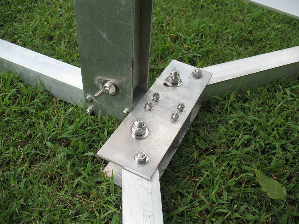
Starting with the oldest piece of ground support I own, is my variation of the ProRail base, made famous by John Coker...

rwo8LcM.jpg


Any launch pad will work, but dedicating a pad strictly for hybrids is a must, due to the amount of support that will be needed on sight. Like everyone here on this forum, I like to build most everything I will use, and I am rather proud of my launch pad. Because of the amount of equipment you will be "humping" out into the field, lightweight is key.

I have owned this pad for a while now, so I felt it needed a little upgrading. I originally assembled the pad with zinc coated hardware, and as you can see, it has become a little corroded. The threads were beginning to seize, so I took this mess...

fVsrGEu.jpg


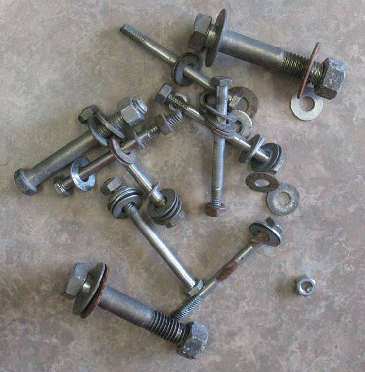
And replaced it with stainless steel from (s)Lowes Rocket Improvement...

vLdoGKH.jpg


This season has also ushered in a blast deflector, as even hybrids can cause ground fires...

aVBfFO2.jpg


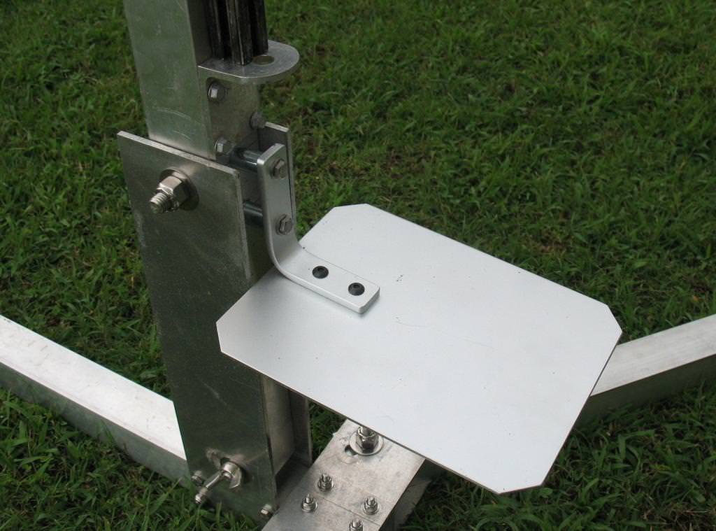
The deflector is away from, and is far away enough from the base of the rocket so not to scorch the end of the air frame.

Next we focus on the heart of the hybrid ground support, the central junction box.
 
Last edited:
Note Here - Inlike my launch pad. I did not build my own ground support, short of merely purchasing what I needed from the sources available to me. My ground support, was built by forum member KarlBaum. We talked at length about my requirements, he offered some suggestions, and he built for me a beautiful and easy to use system. The manifold itself was built by Ron McGough @ Black Dog Rocketry. Both components are top notch, I highly recommend if you are interested in obtaining your own system.

The heart, or junction of a hybrid system is called the "junction box" for lack of a better term. It is here that every circuit is connected, and every signal is passed through, to control a hybrid launch event.

gtzFEG6.jpg


As seen in the image, igniter leads, N2O controls, sensor signals and power hook-ups can be clearly seen. As I add more views of the equipment, I will refer back to the above graphic for better understanding of the junction box's purpose. Let's start with the power source for this system; Power will be provided by "Stanley" a jump starter kit that I purchased from the automotive department at "Wally-World." The orange cable on the junction box with the cigarette lighter plug, will connect directly to "Stanley." Gone are the days of lugging heavy var batteries to the field, this power source is ideal for portability, and benefits from charging directly off of your car, or over night with the supplied cords... The use of this item (not brand) was recommended to me by KarlBaum.

H1kKHId.jpg


In the junction box image you can see a small connection in the upper left hand corner. This is where the vent sensor will be connected. New to me, is the use of a vent sensor on a hybrid launch system. The other end of the vent sensor cable is a vent sensor unit that will be mounted so as to sense the "full" condition on a rocket that is ready to launch. The signal that is sent back through the junction box will register at the handheld device in the form of a blinking LED. We will cover that more when we get to that point in the discussion. The orange cable I believe is self explanatory; it is the circuit that provides the ignition source to actuate the pyro system for motor start-up.

IdnoCVw.jpg


Next we will cover the manifold and main control cable.
 
Last edited:
This hybrid system is designed to fill the rocket with nitrous oxide from a remote position. The set-up is simple; called a manifold, the assembly consists of a large solenoid cable of filling small G-class motors, all the way to M-class. Included is a smaller solenoid to "dump" the system, in the case of a failed launch attempt, and a gauge to indicate tank pressure. The system also has a connection at the fill solenoid for a fill line (more on this later). Each solenoid has a power cord, which will be combined into one NEMA 5-20 plug. This is done so that the plug cannot be confused with the ignition circuit. One of the nice safety features built in by KarlBaum.

XIBaO63.jpg


The manifold, is couple to a 20lb CO2 tank, which I am using as my nitrous supply tank. The supply tank in my ground support has a CGA 660 valve and siphon tube. With a siphon tube, I have the benefit of not having to set the tank on it's end to get the nitrous out. However, I have been informed that the siphon tube will not reach all the way to the bottom of the tank, so I will never see full utilization of the 20lbs of nitrous...

bv5kgOi.jpg


As I update this thread, I will add info here about the fill line used for this system.

For the next will move back to the flight line...
 
Last edited:
Looking back t the junction box image, you will see an RJ45 style connector. This is where the control cable will connect. The control cable is 500' of cat5e cable, which is spooled on a reel. Most of my hybrid flights will occur between 250 to 350 feet away from the flight line, but the system will be M-class capable with safe distances up to 500ft. Stemming from the center of the spool is a small length of cat5e with a junction connector attached. Here I attch a 6ft length of additional cat5e that will connect directly to the hand controller...

wSZ0Gry.jpg


Colored in bright red of course for visibility, so that fliyers can easily see it and avoid tripping over it. The hand controller is a multi-function controller. Here the operator can control the fill, fire and dump functions. There is an LED that is a vent indicator, thus eliminating the need for a person to be close the launch vehicle in order to visually see a venting event. There is also a second LED to indicate continuity of the ignition circuit.

0b4XWub.jpg


NDpSZ0D.jpg


When we have drier conditions outside, I will update this thread with images showing the system completely hooked up, as if to simulate a launch procedure. I am having a fill line built this weekend, and I will be picking up the NEMA 5-20 plug to complete the manifold assembly, at which point the system will be 100% complete.
 
Last edited:
Thank you, I hope someone can benefit... it is not the only system out there, it is just a basic system of my own. HyperTEK is more involved, and this system will not support such systems.
 
My advice for lighter pads with lees longer legs, drill a hole or have an L-bracket at each end.
I would stake it down with some long tent spikes. I have seen video where the torque causes the pad to tilt as much as 4-6" as it runs up the rail.
 
You can easily add on to the GSE to support Hypertek motors. On the launch control side you would need a 12 to 7500 DC volt transformer and an oxygen bottle, regulator, and solenoid which would all plug into the igniter port on the pad module. You would also need a drop stem mountable to the launch rail.
 
My advice for lighter pads with lees longer legs, drill a hole or have an L-bracket at each end.
I would stake it down with some long tent spikes. I have seen video where the torque causes the pad to tilt as much as 4-6" as it runs up the rail.

I had considered this option many times; drilling holes in the end of the legs and bolting on rectangular feet with holes for staking... Good suggestion, thank you!

You can easily add on to the GSE to support Hypertek motors. On the launch control side you would need a 12 to 7500 DC volt transformer and an oxygen bottle, regulator, and solenoid which would all plug into the igniter port on the pad module. You would also need a drop stem mountable to the launch rail.

I started flying hybrids using the original HyperTEK ground support equipment that Star Rocketry would bring out to our launch (prior to our club obtaining their own GSE). The HyperTEK motors were great, but the fill/launch system has some complex procedures that always seemed to hold up a launch at least once or twice during the event... Short of being pyro-free, the system soon had little appeal to me, and I ended up changing over to U/C valve hybrids.
 
I own two different sets of hybrid ground support equipment. The second set is by far and away, the simplest hybrid ground support ever used. There are no batteries, no solenoids, and can be safely used at the flight line. Unfortunately, the motor system this equipment was designed for was not able to reach full popularity due the 2009 court decision to remove APCP from the explosives list. Also, due to the mountains of info which surrounds this monumental event in our model rocket history the topic is not up for discussion on this thread. Just know that the court decision was the pre-cursor to the decline in hybrid propulsion.

Nevertheless, the ground support equipment I am referring to was designed for the Alpha Hybrids motor system. The following image pretty much says it all (mostly)...

L7LE1d1.jpg


The balance of the equipment consisted on a nitrous tank source, a cooler with cool or iced water, and a scale...

prEgrRV.jpg


Simple! The valve connects directly to the source tank. The receiving tank (flight tank) is cooled in the cooler of water to aid in accepting the nitrous oxide, and the scale is used to measure out the proper weight of nitrous being transferred into the flight tank. Also seen the image, the valves are all manually operated. Once the transfer has completed, the motor is assembled and secured into the rocket, and the rocket is launched like any other rocket motor. The whole procedure is deceptively simple, as there are a few more unique steps to the motor assembly process, but bar none, this ground support remains the cheapest for of flying model rocket hybrids... Timing of the Release being what it was, Alpha Hybrids could have gone far at bringing more fliers to flying hybrids.
 
Last edited:
Back
Top