My first rocket (with stabilizing fins)

The Rocketry Forum

Help Support The Rocketry Forum:

This site may earn a commission from merchant affiliate links, including eBay, Amazon, and others.

kavelot

Member
Joined
Aug 2, 2015
Messages
14
Reaction score
0
Hi!
After my first post here ( https://www.rocketryforum.com/showthread.php?127790-what-could-go-wrong ) I studied more and:
1) Ordered the handbook of model rocketry as suggested (but will only receive it by the end of the month)
2) Bought a small rocket and made a static test with an A6-4 engine (because I didn't find a proper place to test it yet)

While I don't receive/read the book, I defined my first goal in rocketry (after successfully launching this rocket I bought):
Make a self-stabilizing rocket (using controlled fins) that can reach at least 500 meters

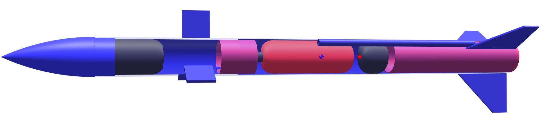
I'm playing with OpenRocket and ended up with the following design. Now I'd like your opinion on this.

WCQp0Bt.png


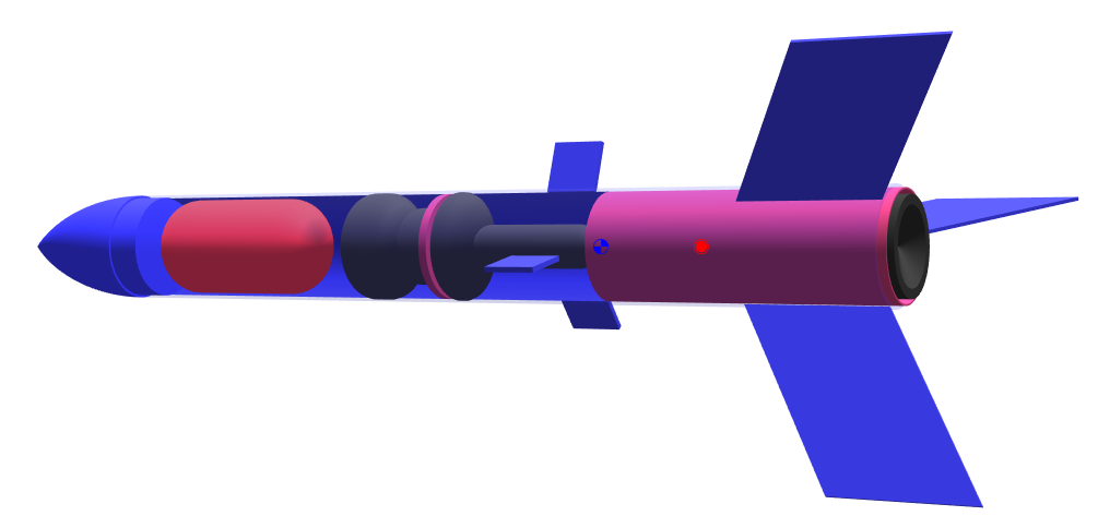
From bottom to top, that's how I imagine it:
1) 3 static fins (probably made of some PVC plastic - like a credit card)
2) Body tube of 65mm outer diameter PVC (2mm thick), length 500mm
3) Engine (I'm making simulations with an I engine (which reachs 1000m height and about 240m/s), but I'll probably start with a C and move at most up to a G)
4) Bulkhead
5) 3 servos + arduino + IMU + small fins (3x3cm)
6) Thick Bulkhead
7) Black powder (to be triggered by the arduino when the IMU detects it's falling)
8) Wadding
9) Parachute (80cm diameter)
10) Nose cone + 9V battery

So, now I need to ask you again "what could go wrong?".

Some unresolved issues I have:
1) I need to calculate the air drag in the control fins to see if the attachment to the servos can handle it depending on the speed. I'm guessing it can since they are small and I don't plan on moving them more than 45 degrees). I guess I'll have the tools to calculate this when I receive the book (I already checked it has a chapter on air drag :)). Also, the control fins size (3x3cm) is a guess.
2) Find a good way to attach the servo to the fins
3) How thick to make the bulkheads so the arduino supports the heat from the motor and the black powder explosion (I'm guessing about 1 gram, but I need to do more tests)
4) How to make the nose cone
5) How to attach the static fins to the body (I'm tending to go with soldering + epoxy)

If everything works as I expect, my plan is to reduce the size of the static fins to the point that the CP goes closer to the CG, as long as the stabilization is working

So, can you see any obvious breach on this idea? Any similar projects I can steal some ideas from?

Thanks
 
6) A C isn't enough motor for this. PVC is heavy and I don't know if you need it that thick. My first high power rocket used a 3" drain pipe and I'm pretty sure that it's thinner that 2mm, I may be wrong. Plan for a minimum of a 24mm mount but I'd really want a 29mm mount. You can adapt down but not up ;)

There are custom nosecone makers, sandman being one. One this size won't run you all that much. He just needs the dimensions and your good to go :)

https://www.sandmandecals.com/
 
Those guidance fins look really close to the CG. If Kerbal Space Program has taught me anything, they won't give you much control authority there.

EDIT: I'd also highly recommend flying the rocket without active guidance first, just to make sure it works as expected.
 
Those guidance fins look really close to the CG. If Kerbal Space Program has taught me anything, they won't give you much control authority there.

from what I understand (at least in theory), if I "raise" 1 fin in one side of the rocket, regardless of where, air will hit it more than on the other side and the rocket will rotate (relative to the CG)
why the position of the fin relative to the CG matter?
 
Having your control forces come from near the CG has them acting on a really short lever arm and thus not producing much of a rotational force. They'll be much more effective farther from the CG.

And yes, it's a good idea to keep your rocket radially symmetric.
 
Those guidance fins look really close to the CG. If Kerbal Space Program has taught me anything, they won't give you much control authority there.

EDIT: I'd also highly recommend flying the rocket without active guidance first, just to make sure it works as expected.

+1. What kind of Arduino are you using? Uno? Micro? Nano? You won't be able to draw power from the Arduino board for more than one servo. In addition, you will probably need to use a lithium-polymer battery to supply the amperage needed for the servos as nine-volt batteries are not very efficient as far as weight and power supply are concerned.

You might be able to use a 18mm motor, I think it has been done before, check this out.

[video=youtube;pTDpV6fkEA8]https://www.youtube.com/watch?v=pTDpV6fkEA8[/video]

I think a 24mm single motor, cluster of three, or a 29mm mount would give more wiggle room for altitude and weight increases.

You do not need to use PVC for the rocket body, cardboard tubes will work fine (Think Estes body tubes.) so long as the structural integrity is maintained. Plus you would not have to make a nose cone! But if you do want to make one, a conical cardstock nose cone that you can make works great, I make them all the time! I do not think an Arduino triggered ejection charge is necessary, just added complexity and weight. Unless you go for duel deploy, but that is another can of worms altogether.

Here is another thought, to have more control over your rocket, it would be a good idea to have the control-fins further from the CG so as to have a larger control moment (I think that is what it's called.:)).

I am pursuing something similar with an Arduino, and speak partly from experience and partly from what I have already learned, so I will be able to help with this somewhat. Of course I do not know ALL there is to doing this, but I think this is a good starting point.

I hope I have not discouraged you, keep pursuing this, I want to see this fly!
 
from what I understand (at least in theory), if I "raise" 1 fin in one side of the rocket, regardless of where, air will hit it more than on the other side and the rocket will rotate (relative to the CG)
why the position of the fin relative to the CG matter?

An applied force through the CG (as is the case if your control fins are located at the CG) will impart no torque on the rocket - so no rotation. This is because T = r * F * sin(theta) - where r is the distance between the axis of rotation (the CG) and the applied force. If this is zero, there will be no torque, and if it is very small, there will be very little torque for a given applied force.
 
Wouldn't having fins in goups of four make the whole stabilizing business much easier? Not that I know but it is an intuition.
 
Updates based on the great input I got here!

1) I changed the design to a 2 tube with coupler... the nose cone+top tube will have the power+arduino+servos+fins, while the second tube is a "usual model rocket" (parachute+wadding+fins+engine)... this means I don't need to electronically trigger the parachute deploy charge (which would be fun, but I don't wanna risk not having it deployed now.. maybe for the next project)
2) For power I found a 300mAh 2s 35~70c 7.4v battery (17g) that will probably do the job (thanks BuiltFromTrash).. btw, I'll be using an arduino nano
3) I managed to reduce the diameter from 60mm to 40mm with a new design of the servos based on the video BuiltFromTrash posted (3 servos stacked horizontally at an angle, with arms to control the fins)
4) This changes + using a 1mm thick PVC tube (I'm thinking about the drain pipe dave carver suggested) reduced its weight (no engine) from 550g to 290g... I'm reluctant to use a cardboard tube... I think a plastic tube will hold the components (and the movable fins) better

As for using 4 fins, in theory 3 should be enough for the job. 4 would certainly make it easier, but would require more amps, and I'm also exactly looking for challenges.

Here's the new model with a G80-7 engine. It would reach 860m and 250m/s:
02aJDHG.png
 
Last edited:
I should also say that I the most powerful motor I have access to is a D6 (I live in south america..), so the only way I can think on making this work is to build my own rocket candy motors
the test motors will be probably based on just a 10cm PVC pipe filled with rocket candy with a hole in the middle
if this works I could try making better nozzles and so on, but I'm way more interested in the "electronic control" than in propulsion, so if what I get is good enough I'll probably not spend too much effort trying to improve it

in any case, I'm following this youtube series for reference: [video=youtube;BfAZx4FPNkA]https://www.youtube.com/watch?v=BfAZx4FPNkA[/video]
 
Being in South America does complicate thing but you might contact the 2 major motor manufacturers (AreoTech in the US and CTI in Canada) One or the other might be able to help. I know there are others down South, I don't know what countries, but there's a group in Brazil for instance who might be able to order with you spreading the cost out. If not then sugar motors will have to do, just be careful ;)
 
from what I understand (at least in theory), if I "raise" 1 fin in one side of the rocket, regardless of where, air will hit it more than on the other side and the rocket will rotate (relative to the CG)
why the position of the fin relative to the CG matter?

If the surfaces are located at the CG, they will be effective in roll (only slightly, due to the short length) but have virtually no effect in pitch and yaw. It's all about moment arms...
 
Last edited:
I had another (probably too bold) idea
Do you think there's any chance, with a similar design to the one I posted (with probably bigger control fins), to stabilize a free-fall descend of the rocket keeping nose cone UP?
I'm guessing I'd need to move the CG closer to the CP (specially because it will raise after the fuel is burn), which I could do if the stabilizing works well

The bold idea here is to try to make the rocket go up with an F or G engine, fall back nose cone up, trigger a smaller motor closer to ground and basically "land" (probably not very soft, but this would be cool anyway)
I don't want to discourage you, but the landings you describe sounds very near impossible if you are not some sort of very serious space agency. Please prove me wrong, but there is no way I can imagine this happening.

You don't seem to have much experience with rockets and little training in physics. This is far from being a bad thing since you have all the amazing parts of building and flying to learn as well as a world of amazement learning about physics. This is almost a geek wet dream!

If I was in your place, I'd start by building and flying a small and simple rocket, then a bigger or more complex one and so on. You would learn invaluable lessons about what feels doable and what not.

Good luck in your endeavor!
 
Back
Top