Super Firecat

The Rocketry Forum

Help Support The Rocketry Forum:

This site may earn a commission from merchant affiliate links, including eBay, Amazon, and others.

EXPjawa

Well-Known Member
Joined
Jan 27, 2015
Messages
2,218
Reaction score
94
Location
Middlesex, NY
Some folks might remember the Estes EAC Firecat - a factory kitbash of the early '70s Honest John and the Bandit, into an entirely different looking new model. The Firecat was only sold to members of the EAC, so it never appeared in the main catalog. Take the HoJo nose cone, tube, rework the fins, make a few other bits from the scrap balsa sheet, and throw in decals from the bandit. Oh, and a bit of BT-48 tube for how knows what reason. Somewhat recently, someone that flies with my nephew at LUNAR launches gave him an unfinished Firecat, which prompted a bit of research into what it actually was. This led to me building a clone:
WP_003452.jpg

And anyone that has paid attention will not be surprised that this further led to wanting to build an upscale. When I first built the clone, I modeled in Rocksim so that I could make sure that it would still be stable if I used basswood instead of balsa for the complex fin structure. Once I had that, scaling it up was easy - except for the nose cone. I really wanted to go up to BT70 size, like I've done on a number of other projects, because I really like the size and it lends itself to a nice midpowered scale rocket. This one would be a little less than 3' long at that size. However, I couldn't find off the shelf HoJo nose cones for anything larger than 1.6" that wasn't a giant fiberglass piece.

So, I decided to commission Sandman to make me the cone and decals, while he was at it:
WP_003418.jpg WP_003460.jpg

This cone is more true to scale, whereas the original one used a shortened semi-scale cone, so that will alter the size or proportion of the finished product. Some thought was required to decided what to do with that...
 
OK, so moving along, here we have the Rocksim for the Super Firecat:
Firecat 70.jpg

This now reflects the actual nose cone that Gord made for me. It wound up a little different from what I'd requested - which was a scaled up version of BNC-50BD - but what he made was the more scale-like -50HJ upscaled cone. And that's fine, but like I said, its stretched out over the original design. So either the model is about 3.5" too long to be a true upscale or the proportion of nose cone to body tube are off. Normally that wouldn't be a thing, since that would be more or less hidden by the common diameter. But since the cone is flaired, it becomes visually obvious.

Anyway, I moved ahead with the fins while contemplating the length issue. I printed out the fin patterns, used them to make cardboard patterns, them transferred to ply stock. Ordinarily I would've use 1/8" ply or basswood for something this size, but due to experience with tip fins on my Jayhawk, I decided that these needed to be more robust. I used 3/16" aircraft ply, which has the virtue of being close to correct for upscaling the original 3/32" finstock. Marked out:
WP_003457.jpg

You can see from the picture that I decided it was necessary to tab the rudders and tip winglets together on the wings. Again, the tip fins on my Jayhawk are surface mounted to the end of the wing, and they break every other launch. So here, I've made the pieces interlocking, as close to through-the-wall as sheet ply would allow. Here, the thicker stock also helps provide more positive tabs. And of course, the wings are TTW to the motor tube. Then a trip to my folks' house to use my father's band saw and belt sander yielded this:
WP_003467.jpg

So, the next step is to finish sand the fins and fit the assemblies together. I'm debating whether the entire wing structure should be assembled and then attached to the body, or if I should attach the wings first, build the rudder/winglet assemblies, and then attach them to the wings last. It'll depend on if I can fit the wing assembly onto the fin jig all assembled up. Being able to assembly the entire wing structure first will let me use clamps to hold it square. I'm not sure I could do that if the wings are attached first.
 
Rick, I'm also in the process of an upscale to BT-80 of the EAC Firecat. It's interesting to me that you ran into the same issues as I have (i.e. nose cone shape & fin strength). My clone used the BNC-50BD (sourced from Semroc/eRockets), but I had already purchased a fiberglass HoJo cone from Madcow before I realized the fact that the Firecat was not actually using the HJ cone shape (that'll teach me to assume - I had initial measurements of a friend's original Firecat and had assumed that the Firecat was an SPEV of HoJo kit parts and excess Demon decals). At this point I'm thinking I'll use the HoJo cone for an "uprated" Firecat - maybe "Firecat II", with improved fin shapes and such, while I try to decide what direction I'm going on the "pure upscale" idea.

I *had* planned on heading down the path of getting Gordy to turn me a BNC-80BD (as it were), but seeing as how you ended up with an HJ shape, I won't be doing that without sending him my BNC-50BD as a pattern. :)

If you don't mind, I'll post a pic or two of my project in this thread --- but if you'd rather I create my own and not interfere with yours, I'll happily move to another thread. Don't want to hijack! :)

I'm including a reference pic of cones involved in this project -- the top one is the BT-80 fiberglass cone from Madcow (supposed to be the M31 round); the middle plastic cone is from the currently available Estes mini-HoJo (the M50 round), while the balsa cone at the bottom is the BNC-50BD from Semroc/eRockets. As you can see, they are all slightly different, and will make this project most interesting...

photo.jpg
 
I don't mind you posting your pictures here, but it might be confusing to other readers. And, we the more Firecat awareness we have, the better!

Anyway, what I did with my Attack Craft Orion clone to account for the changes that were made to the PNC-50 nose cone was to deem it a "Block-2" aircraft; an upgrade, revised version. As such, I've taken some liberties with improvising some other changes as well. I haven't posted any pictures of it yet since it isn't finished (and I didn't take any initial photos for a build thread). That's another one I'd like to upscale, but that nose cone is even more of a problem.

With your clone, what did you use in place of the of the BT-48 tube for the faux-engine pod on the bottom? Its odd to me that Estes would've used a unique tube that was so close in size to the standard BT-50. I wound up using a piece of BT-50 coupler instead, which is slightly larger than the BT-48, but its close enough that I don't care. For the upscale, I found that a piece of the #200 tube that Semroc sells is very close in size to a correct upscaling. The bigger issue that I'm still trying to sort out is where to place rail guides on the upscale. They have to be on a standoff, there are few places where they could be placed. I'd rather use buttons than a 1/4" lug (show inside the faux engine in the sim file).
 
With your clone, what did you use in place of the of the BT-48 tube for the faux-engine pod on the bottom? Its odd to me that Estes would've used a unique tube that was so close in size to the standard BT-50. I wound up using a piece of BT-50 coupler instead, which is slightly larger than the BT-48, but its close enough that I don't care. For the upscale, I found that a piece of the #200 tube that Semroc sells is very close in size to a correct upscaling.
With the diff between BT-48BE at 0.902" ID/0.928" OD and BT-50 at 0.950" ID/0.976" OD, I just went with a piece of BT-50 as the faux-engine pod on the clone (at only .05" diff, at a couple feet away, I honestly can't tell the difference). I suspect that, like the BNC-50BD nose cone, the BT-48BE tube was a part that Estes got "stuck with" and SPEV'ed the Firecat with it to get rid of it. So far as the upscale goes --- I agree, the #200 tube was my chosen tube. Great minds thinking in the same direction (or a limited set of parts suppliers) is probably what drove us both in that direction. :)

The bigger issue that I'm still trying to sort out is where to place rail guides on the upscale. They have to be on a standoff, there are few places where they could be placed. I'd rather use buttons than a 1/4" lug (show inside the faux engine in the sim file).
I'm using a slightly different approach on the upscale. Instead of a simple "strake" running along the top of the drone, I was planning to convert it more to a "conduit"; either conforming a half-round dowel to the top (which could then have rail buttons installed into it as "quasi-antennas"), or creating a scoop-like long "box" (ala the Estes QCC Explorer, but only 3 sided), and anchor the rail buttons into the top of that box. I agree, there just isn't really any other way to pull it off (since that bulbous nose cone just gets in the way).
 
I try at all costs to avoid putting buttons on the top of the model; I want that side to face the flight line. For this size model, I'll probably use mini-buttons rather than full sized 1010 buttons. With that in mind, I was actually thinking about putting them in the engine pod. At about 2" in diameter, a 20mm square rail will easily fit in it. The buttons could be threaded into the 3/16" plywood pylon and will quite sturdy. The question just becomes a matter of how to access them. I could simply put some holes in the bottom of the faux-engine tube to allow screw driver access.

The other question I have is this - if I'm upscaling to BT-70, and you're going to BT-80, how'd we both arrive at #200 tube? IIRC, it should be slightly undersized for my version, but a 1/2" too small for you if I'm doing the math right...
 
The other question I have is this - if I'm upscaling to BT-70, and you're going to BT-80, how'd we both arrive at #200 tube? IIRC, it should be slightly undersized for my version, but a 1/2" too small for you if I'm doing the math right...
Don't assume your math is wrong...I've slipped more than one digit in my life. :) I'll double-check, but I was sure ST-200 was what I'd settled on - but my wetware has been off on more than one occasion since I passed 50 solar orbits a few years back.

I certainly understand and agree with your "bottom mounted buttons" approach - I just headed down a different road. Will be following your thread here with interest. Hoping to get mine in the air before the end of the flying season this year, but lots going on...she might not catch sky until next Spring. We'll see. :)
 
You must be right...I took the calipers to the tubing and I'm getting an OD of 2.247, which is more than ST-200 but less than BT-80. It's a little bigger than BT-70, too --- a chunk of that on my calipers is showing 2.1".

When I pulled it for the upscale and stuck it in the box with the other parts, I could *swear* I grabbed it from my Semroc stash, but maybe it came from another pile...it's been a few weeks since I did it, so who knows? :)

In any event --- I'll dig around and see if I can characterize the tubing. Not that many manufacturers floating around (unless I bought it awhile ago and just grabbed it from the spares box. Ugh!)
 
Well, I decided that I'd essentially split the difference between making the rocket 3.5" too long or the body tube 3.5" too short. Basically, I shortened the body tube an inch and a half, and let the rocket overall length grow 2". That seems to give the best proportions overall in the sim file, aesthetically speaking. So that makes my body tube an even 20" long, so I set about cutting that down and marking it out.
WP_003462.jpg

Once marked, then I cut the slots:
WP_003464.jpg

That was set aside for the moment, and started the motor mount tube. I found a piece of 29mm tubing in my box that was already the needed length, so that part was easy. I fished out some centering rings and glued them up:
WP_003465.jpg

Next, I'll have to cut a notch in mid ring for the tab on the ventral pylon to locate on. Admittedly, that would've been easier to do before gluing it in place, but sometimes one gets ahead of one's self. I've also concluded that I can mount up complete wing assemblies on the fin jig, so I'll build them first before attaching the wings. That will let me clamp up the rudders to the wings, and then the winglets to the rudders while the glue dries.
 
Last night, I glued up the wing assemblies for the Firecat:
WP_003469.jpg

Both rudders on:
WP_003470.jpg

And the winglets. This shot shows the tabbing pretty well:
WP_003471.jpg

For scale reference:
WP_003474.jpgWP_003473.jpg

Or, I guess I could use these together for some kind of funky T-tail on an airplane...
WP_003472.jpg

The next step for the wings should probably be filling/blending/filleting to tie the corners together, given that I rounded and airfoiled the edges of everything first. The corners where they meet need some filler. And I'll have to install the motor mount before I can attach the wings.
 
A note on the BT-48 tube... The Firecat is a kitbash of the old Estes Coldpower Honest John. The BT-48 was the piston tube than ran up inside the main body to eject the parachute.
 
A note on the BT-48 tube... The Firecat is a kitbash of the old Estes Coldpower Honest John. The BT-48 was the piston tube than ran up inside the main body to eject the parachute.
Scott, you da man. Thanks for the info - I've been puzzling over this for a number of years. Glad to hear the straight! :)
 
Rick, your tabbing method on the wings/fins is inspired. Should make for some very strong joints. I'm curious what your experience with them turns out to be (i.e. strength on landing shock), especially those "winglets" on the outer edge. :)
 
Well, we'll see. Like I said earlier, the tip fins on my Jayhawk model have been a constant source of breakage, to the point were I keep thinking I'll have to retire the model (and then I fix it again). This is sort of like building a drawer; combined with some epoxy fillets, it'll probably wind up stronger than the wing attachment to the body tube...
 
Scott, you da man. Thanks for the info - I've been puzzling over this for a number of years. Glad to hear the straight! :)

No problem :D ... I love the Firecat and even with all of the kits I've been able to get, I've never even seen a Firecat kit in person. I'm thinking of bashing the new Estes BT-60 HJ into one when it comes out.
 
I'm thinking of bashing the new Estes BT-60 HJ into one when it comes out.

I considered the same thing, but a) I didn't want to wait until who knows when Estes will release it, and 2) I didn't think that BT-60 based model would be quite big enough... :)
 
I guess I'm overdue for an update. OK, I marked and notched the tab on the faux-engine pylon to mate with the middle centering ring, since its tab intersects it:
WP_003475.jpg

It was slightly tricky due the different material thicknesses, but once I got things sorted it fit nice. I double checked that it fit the same with the MM tube in the body tube, and had a good tab fit either way. I decided what to do with the rail guides - this pylon is 3/16 ply and has the height to get the rail around the cone. So, I'm going to put the buttons inside the faux engine afterall. I elected to offset them a little farther, to get the square rail away from the side of the circular tube, so the that corners of the rail have plenty of clearance. I started with mini-buttons, and replaced the screws with some longer self-tapping screws from a old drill that I took apart (to use the chuck on my launch pad!). I used an extra button collar to provide the spacing:
WP_003476.jpg

Then, the pylon was drilled for the screws and the buttons installed. The plan is to cut two small holes in the body tube that comes the faux-engine, so that the tube will slip over the buttons. For that, I'm using a #200 tube from Semroc, however when I received that order, apparently eRockets forget to include that line item so I don't actually have the tube yet. I just got an email from Randy saying that it would shipped today. Anyway, the pylon with the buttons:
WP_003477.jpg

Next step: installing the motor mount. I forgot to photograph this part, but I looped a segment of kevlar cord through a hole drilled in the front centering ring and tied it around the MM tube. Then the loop was epoxied in place. After marking out the desire length, I tied a loop in the end that I can either clip a D-ring into or perhaps directly tie a length of 3/8" elastic cord to. The kevlar is short enough that its below the top of the body tube and not likely to zip through it, but long enough to be easy to reach. Then the mount was glued into the main body tube and internally filleted:
WP_003487.jpgWP_003488.jpgWP_003490.jpg

Now that this is in place, the task is fit the tabs of the wings and trim them into place. Last night, I did a bit filling/blending, sanding/filing to close the gaps where the airfoiled edges join together, and to knock off the square corners where the base of the rudder was next to the airfoiled wing edge. I should be able to finish sand that and apply epoxy fillets tonight, and once that's set up, attach the wings to the body tube. Then, the only part left to make with be the dorsal strake/raceway that runs the length of the top. Things are coming together...
 
More fanding and silling. I attached the starboard wing assembly using the fin jig:

WP_003498.jpg

The port wing should come this evening, but I have a little more sanding to do on areas I just added some more filler to first.
 
Second wing on:
WP_003503.jpg

Also, a package arrived from eRockets containing the #200 tube needed for the faux engine. And I bought some basswood stock from Hobby Lobby to make the raceway from. So, I have everything except a parachute...
 
Last edited:
More progress. Attached dorsal raceway:
WP_003530.jpg

And attachment of the #200 tube that is the faux engine pod:
WP_003531.jpg

After preliminary checks with fitment against the mini rail, I found that I didn't need so much stand off, so I shortened the button spacers. I also decided that I needed the forward button to be a bit farther toward the front, as having both buttons in the pod let had too much potential for the rocket to tip into the rail, and strike the nose cone. So I made a small standoff pylon and shaped it like an antenna vane or something similar. The standoff is viable here (forward button not installed yet), in the background. This shows the aft button inside the pod:

WP_003533.jpg

Now that this is all done, thing looks outwardly complete. It just needs to have the internal fillets done and the aft tube closed up and motor retain attached.

WP_003534.jpg
 
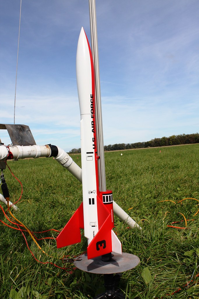
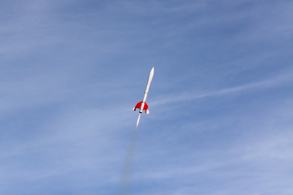
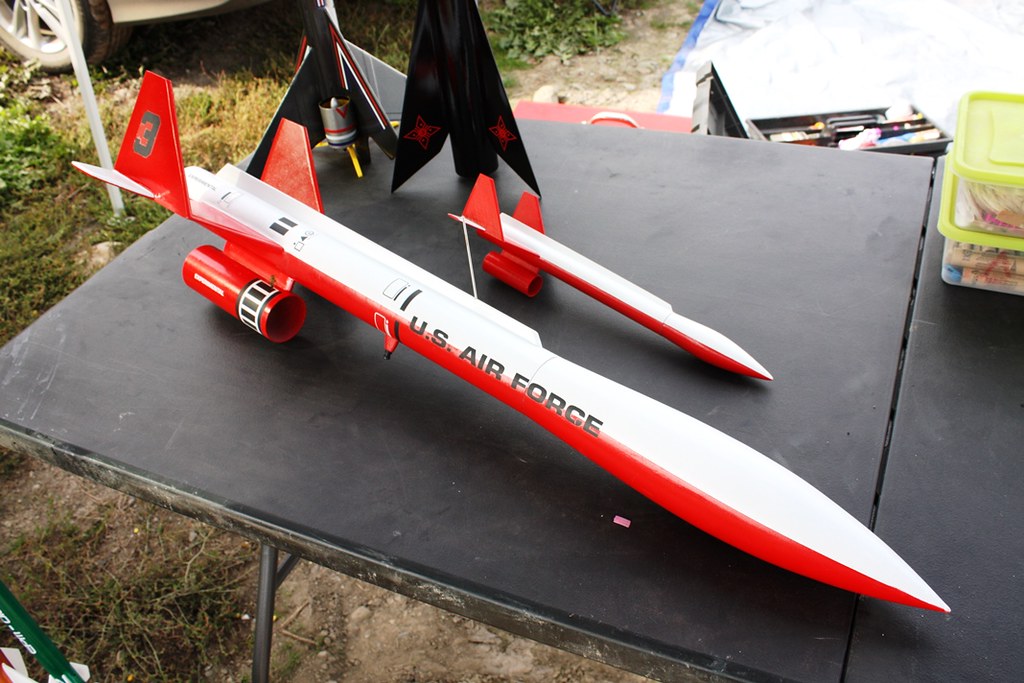
This appears to be another one that I forgot to update after completion. This was finished and flown twice late last summer. I wound up replacing the 36" Top Flight Crossfire chute that bought for it with a thin-mil chute of the same size, since I couldn't pack the Crossfire small enough to fit in a BT70 tube. Fortunately, Ken Allen was onsite with one in his trailer. Anyway, here it is:

21942832426_4faef35400_b.jpg


21781145208_5442647e95_b.jpg


21599483998_79aa552247_b.jpg
 
Back
Top