Apparition - Build Thread

The Rocketry Forum

Help Support The Rocketry Forum:

This site may earn a commission from merchant affiliate links, including eBay, Amazon, and others.

LW Bercini

Well-Known Member
TRF Supporter
Joined
Jun 15, 2011
Messages
2,622
Reaction score
147
Location
Macon GA
Subsequent to my posting pics of my most recent scratch builds, I've been asked about doing build threads.

Previously, I have shied away from them because my projects tend to progress in fits and starts. I didn't want to create a thread and have it drag on and on.

But this current project seems simple enough that I can give it a go.

Of course, we need to kick this off with the requisite picture of the parts, and a drawing of the design:

19784971076_56acbbc962_k.jpg


19370323358_d9f6bcc88c_z.jpg
 
Last edited:
First of all, let me apologize in advance about the pictures. Either my camera, or the photographer, or a combination of both, are not up to the task of taking close-up shots.

Secondly, I am taking the time to make comments about some of the techniques I used (or discovered) during the build. If you don’t want that level of detail, please let me know and I will omit them going forward.

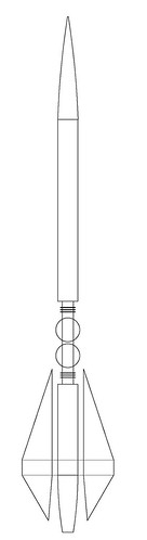
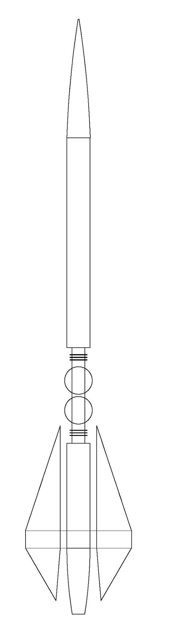
At the outset, I realized I have not determined the length of the central BT-20 tube. That is because it is depended on 2 unknown lengths: the length of the boat tail, and how much space will a ping pong ball take up. So before I do the build in earnest, I need to get those 2 lengths figured out.

A few years ago, I had this “brilliant” idea of using paint stripper to clean up an old Estes Comet kit for repainting. I did not know then what I know now – paint stripper does not play nicely with plastic parts. The stripper fused the old primer into the surface of the plastic, leaving behind a lumpy, rippled surface, and completely destroyed the step-down of the shoulder. But with this build, I have a chance to repurpose this poor excuse of a nose cone into a tail cone. I have done some sanding to work all the ripples out, but there are still a number of pits and dents that I will remediate during finishing steps.

18999018163_e544719281_z.jpg


I needed to remove the cone-shaped protrusion from the bottom of the former nose cone in order to allow space for the ring supports which you will see in a later step. By wrapping several layers of masking tape around the shoulder, I had a guide that I could seat the razor saw against, allowing a reasonably straight cut.

19431981990_229fd1c90a_n.jpg


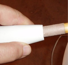
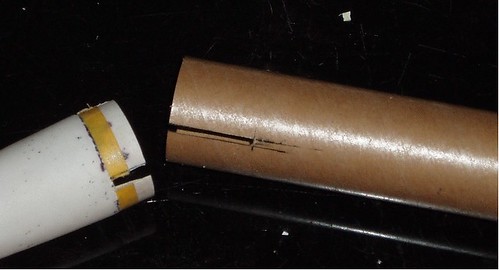
Next, was the step to remove the tip of the former nose cone. I knew the cut didn’t have to be perfect, since it would be sanded to the final size, but starting out with a cut that is very close to being at right angles to the center line decreases the amount of swearing polluting the air in my workshop. Here is my simple technique for marking the cut line. I put a small section of body tube on the shoulder section so that I would have something to hang onto. Then my holding a 2050 centering ring stationary in one hand, I slowly “screwed” the cone into the ring as if I were screwing in a light bulb. By turning the cone as I pressed it into the ring, it kept it going straight in. After marking a line around the ring I cut off the tip with a razor saw.

19431980710_05bd4e34d0.jpg


At this point, the opening is not large enough to accept a tube, and needed to be sanded to size by alternating between sanding against a flat surface, and thinning the wall from the inside. One unknown length down, one to go…

19433359189_c29358f0ae_m.jpg
18997378224_8159b2ba7d_m.jpg


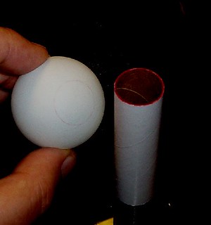
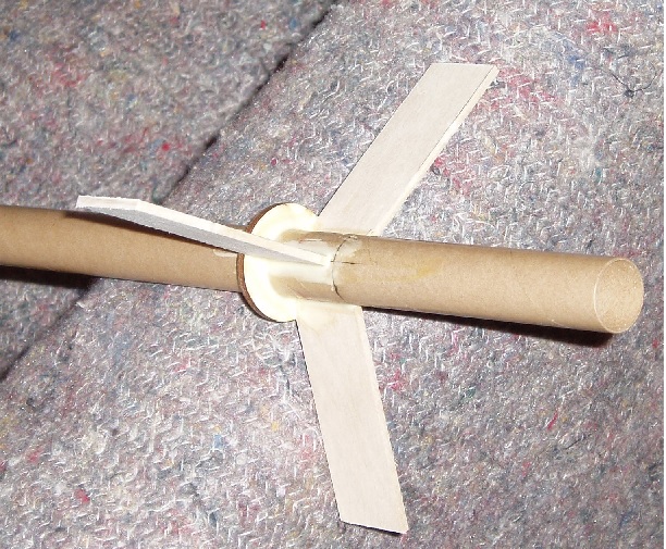
This is the very first time I have ever used a ping pong ball on a rocket. And since Shrox is not here to edumacate me on the definitive technique for cutting holes in them, I was on my own to figure it out. My first step is to mark the circle. By covering the end of a tube with ink, I “stamped” a circle on the ball (The circle came out a bit faint, so I played with the contrast of the picture so it you could see it).

19612944002_8fa6a477c4_n.jpg


The first thing I learned was that even with a brand new blade, there was no easy way to cut into the curved surface – I could not control the blade well enough. So I came up with the idea of perforating around the circle using a straight pin. Then I could use my knife tip to cut between the holes.

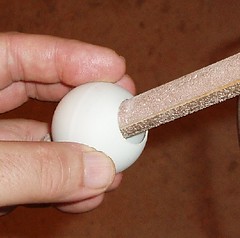
Then using the same sanding rod I used to thin the wall of the boat tail, I sanded the opening until it was the correct size. However, I discovered that pushing in and out of the hole was not going to work with the more fragile ping pong ball material. Instead, I held the sanding rod stationary while I twisted the ball back and forth (think of the motion of turning a door knob back and forth).

19431924328_14dbd7b4e0_m.jpg


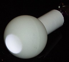
Once the first hole is done, by pushing in a tube until it seats firmly against the interior of the ball, it shows the location of the next hole. But how do you mark that? I’d like to credit Gary Byrum for this next technique. By illuminating the ball from the inside, using my handy dandy Sirius Rocketry mini flashlight, I could clearly see the circle I needed to mark. Then I used the same techniques as before to do the second hole.

19619960855_5094f7dbcb_m.jpg


Final unknown length determined. And this is all I got done last night.
 
Last edited:
Details are always good! Making a good tail cone out of a nose cone just takes some hack & slash followed by patient sanding to get the right size. Cutting ping pong balls again just takes a bit of patience, with careful and light cuts eventually going through for a nice edge.
 
The three ring support spars will bear the brunt of the aerodynamic forces for this design. Since these spars have root edges only 1” long, and have high aspect ratio, I have decided to go with a through-the-wall installation, even though this is a low power model. I made the three ring support spars from 3/32” basswood.

Using Titebond II, I attached the support spars to the BT-20. Once they were in place, I butted a 2055 centering ring against the top of the support spars. Adding the ring not only helps position the BT-55 tube later, but by having fillets between the ring and the spars increases their strength. Here is a pic of the support spars and ring in place, and freshly filleted.


19601062548_d1a61d72b7_o.jpg


While that is drying, I cut 6” off the BT-55 tube and marked the end for 3 fins. On the other end, I glued in a 2055 ring flush with the end of the tube. Using scissors, I cut 3/32” by 1” slots in the tube along the fin lines. I also cut away matching sections from the shoulder of the boat tail.

19168175633_ed10307325.jpg
 
Last edited:
Ok, I should have done this earlier, but I am not so far into the build that I can't pause to do this now.

Let's take another look at the overall design:
19784971076_7bfa10f8e3.jpg


When you don't have a set of instructions, you need to look at your design and think about how the parts "interract" - that is, what is next to what, what attaches to what, what overlaps what. Where does the launch lug go? How hard will it be to fill and sand the wooden parts? Should any of the parts be painted before being glued on? (This, by the way, is an excellent question to ask yourself even when you are building a kit. If you think what would be involved in painting -- and especially masking -- you may consider changing the order of some of the steps to allow finishing/painting some of the components before assembly)

Here is what I figured out by studying my design:

1. Since the ping pong balls have a larger diameter than the BT-55, my lug requires a stand-off

2. The way the fins extend upward, I need to put those little ring details on before the fins.

3. Since I want to paint the midsection a different color than the rest, masking will be a lot easier if I do that before I install fins and tail ring.

4. The tail ring would block the ability to paint the fins, therefore it must be installed after painting. This means that both the tips of the fins and sections of the interior of the ring must be masked before paint in order for there to be raw surfaces for gluing

5. It is not visible in the line drawing, but the fins are actually parallel pairs of fins. If I want to get nice paint coverage on the facing surfaces and edges, each fin needs to be painted individually before assembly. Again, this means portions must be masked to protect the gluing surfaces.

With these conditions established, some of what you see in subsequent steps will make more sense.

Not that I am ever totally sure I am making sense...
 
Great design. I'm looking forward to watching it take shape. Subscribed.
 
Six months later....

WOW! It's hard to believe so much time has passed since the last time I visited this forum!

Well, I did finish the build. Below is a pic from the maiden flight. I took pics of the build process, but just never got motivated to post them here.

If I can get MORE THAN 2 people ask me for it, I will post the rest of the build pics

23107753860_055efd7a2b_o.jpg
 
Last edited:
Of course! I only got to help draw this baby. Darn tootin' I wanna see how it went together, even though you did explain it to me.
 
I should also mention that (a) I never really understood the design until seeing that finished picture (although there are still a couple of details I'm not clear on). Build pics would definitely be helpful to fill in the blanks, and (b) I was actually planning to ping this thread at some point to see whatever became of it. So thank you for doing it for me. :)
 
You mention the fins are really a pair in parallel. Are they mounted on each side of the ring support spars?
 
Lawrence,

I think you'll have that empty feeling the rest of your life if you do not post the rest of the build thread. Not to mention so very many people logging in daily, hoping to see just a bit more ... :)
 
Lawrence,

I think you'll have that empty feeling the rest of your life if you do not post the rest of the build thread. Not to mention so very many people logging in daily, hoping to see just a bit more ... :)


I've been waiting on the weekend so I can have a block of time to get the pics hosted so that I can insert them in-stream with the text.
 
Then I glued the tube/fin assembly into the pre-slotted body tube and applied some external fillets to the spars.


19784601826_ffc7f46d75_o.png


After those set up, I applied some internal fillets to the BT-55/spar joints, making sure that I did not get any glue on the tube interior where the boat tail would go later. (Sorry about the photo quality. I simply could not get close-up pic without the flash "bleaching out" the detail)

pic

19624174439_3aa7f25226.jpg


Unfortunately, I was so focused on photographing the interior, I didn't notice the mistake right in front of my eyes.

24793820750_7f5bfae07d_m.jpg


It was not until I finally epoxied the boat tail in place, did I see my mistake


19975031855_3123e1a710_n.jpg


"No biggie", I thought, "I'll just patch this up with putty" Nope! I worked and worked on getting this joint smoothed out with putty and sanding and sweat and tears. I managed to get it subdued, but finally gave up on trying to get it completely fixed

LESSON LEARNED: slotted LPR tubes are really flexible. I should have temporarily inserted the boat tail when I did those external fillets. Then I would have made sure the tube portions were seated down in the correct position.

Lastly, I installed an engine block in the motor tube so that the motor would extend 1/8" from the rear of the tube.
 
Last edited:
How did I miss this? :confused2:

Looks like a lot of fun!

If you can get me some additional info on parts and such, I can see if I can whip up a .ork file for it.
 
If you can get me some additional info on parts and such, I can see if I can whip up a .ork file for it.

I really appreciate the offer, K', but I'm afraid it might be an awful lot of work for almost no payoff.

Obviously, the design work is completely done (I used BrainSim 6.0 for that). And given the 18mm motor mount, there are a very limited number of C and D motors available that will fit it.

But I am in no way the "Open Rocket Whisperer", so you may have insight I do not....

Lawrence... I have no rockets here in China (I'm living on less than 15USD/day at the moment)(doable for the short term, but not sustainable). So, I have LOTS of spare time, and it's a way of keeping me in the game. If you want I'll do it, if not, I'll let it drop. I just thought it would be kinda neat to try (haven't tried ping pong balls yet).

Keep in mind... I sim for appearance, not for actual flight characteristics (unless it's one of my personal designs (e.g. OFFl).
 
Last edited:
Before I can finish assembling the airframe, I need to install the the "fiddly-bits" in the center. There are 4.5' of BT-20 exposed between the two 2050 centering ring. In the pic below,one of the 2055 rings is already installed, and is flush with the edge of the BT-55. Measuring up 4.5" from there, I placed a tick mark for where the top-most 2055 ring would go later. In the pic below, the mark you see on the far left shows where the 2055 ring will go later.

Measuring inward from those two ring locations, I placed 4 marks, 1/8" apart. Then, using one of those 1/4" wide cardboard 2050 centering rings, I marked alignment lines around the tube for the first 3 of the 4 marks:


24462475643_06a077a527_c.jpg


I learned from experience, many years ago, that those old-fashioned paper centering rings are really flexible, making it a real challenge to keep them parallel to each other. For this step only, I used white glue because it is thinner, and would allow me a bit more time to adjust alignment. Starting on the motor mount end use a toothpick to apply a narrow line white glue around the alignment line. Then using the 1/4" 2055 ring as a "push tool", slide the paper ring up to, but not past, the alignment line. When you do this, the glue pushes up above the alignment line.

I used a cotton swab to smooth out the excess glue, forming a fillet around the ring joint. The entire time, I kept the 1/4 ring pushed against the paper ring to prevent it from sliding or flexing. Once the fillet is done, remove the 1/4" wide ring. Take your time here and allow the glue to get well set before you go onto the next ring, otherwise as you swab the glue on the subsequent ring, you might push the prior one out of alignment.


20444657344_d5a0930749_c.jpg


Continue working from the motor end, installing ring-ring-ring-ball-ball-ring-ring-ring and finally the other 2055 centering ring. The final configuration looks like this, with everything centered between the two 2055 rings:


21041055496_1b1edcc9ce_z.jpg


You will notice that the space between the ping pong balls is wider than 1/8". Since I did not really know exactly how wide the cut ping balls would be, my measurement of 4.5" of exposed BT-20 was a smidge off. I anticipated this might be the case, and that is why I measured the tick marks from the 2055 rings inward. That way I made sure the end result was still centered.
 
Last edited:
Next, glue on one more 2055 centering 3" forward of the one you see above. Put a notch in outside edge of the ring. Tie the elastic shock cord around the BT-20 and fillet into the centering ring and tube joint. Feed the free end of the shock cord over the notch and tuck into the BT-20 to keep it out of the way during the rest of the construction


24971178002_9b85a9b5e3.jpg


One of the things I like to do with launch lugs is to incorporate them into structural elements. This time, I laid the lug into a 3/8" plank of balsa, and then flanked it with 1/8" balsa strips

21041053396_fb7c37cf3f_n.jpg


Then using a razor saw and a miter box, cut the ends to 45*

21041053936_ba3c2a45ff_n.jpg


Finally, I rounded the top and ends until I had a little lug "hot dog"

21074934671_05914092c6_n.jpg


The upper BT-55 tube is glued on so that the centering ring next to the paper rings is flush with the bottom end of the tube. The "hot dog" is glued to that BT-55, also flush with the end of the tube. Make sure the lug assembly is not in the way of one of the support spars.

20444665234_5cef87fc39_o.jpg
 
Last edited:
Back
Top